Tensator RFIOBRD00 Transceiver and Remote Control unit for Tensator E-queuing system User Manual
Tensator Limited Transceiver and Remote Control unit for Tensator E-queuing system
UserManual.wiki
>
Tensator
>
RFIOBRD00 User Manual
User manual
Navigation menu
Upload a User Manual
Namespaces
Wiki Guide
HTML
PDF
Info
Views
User Manual
Discussion / Help
Navigation
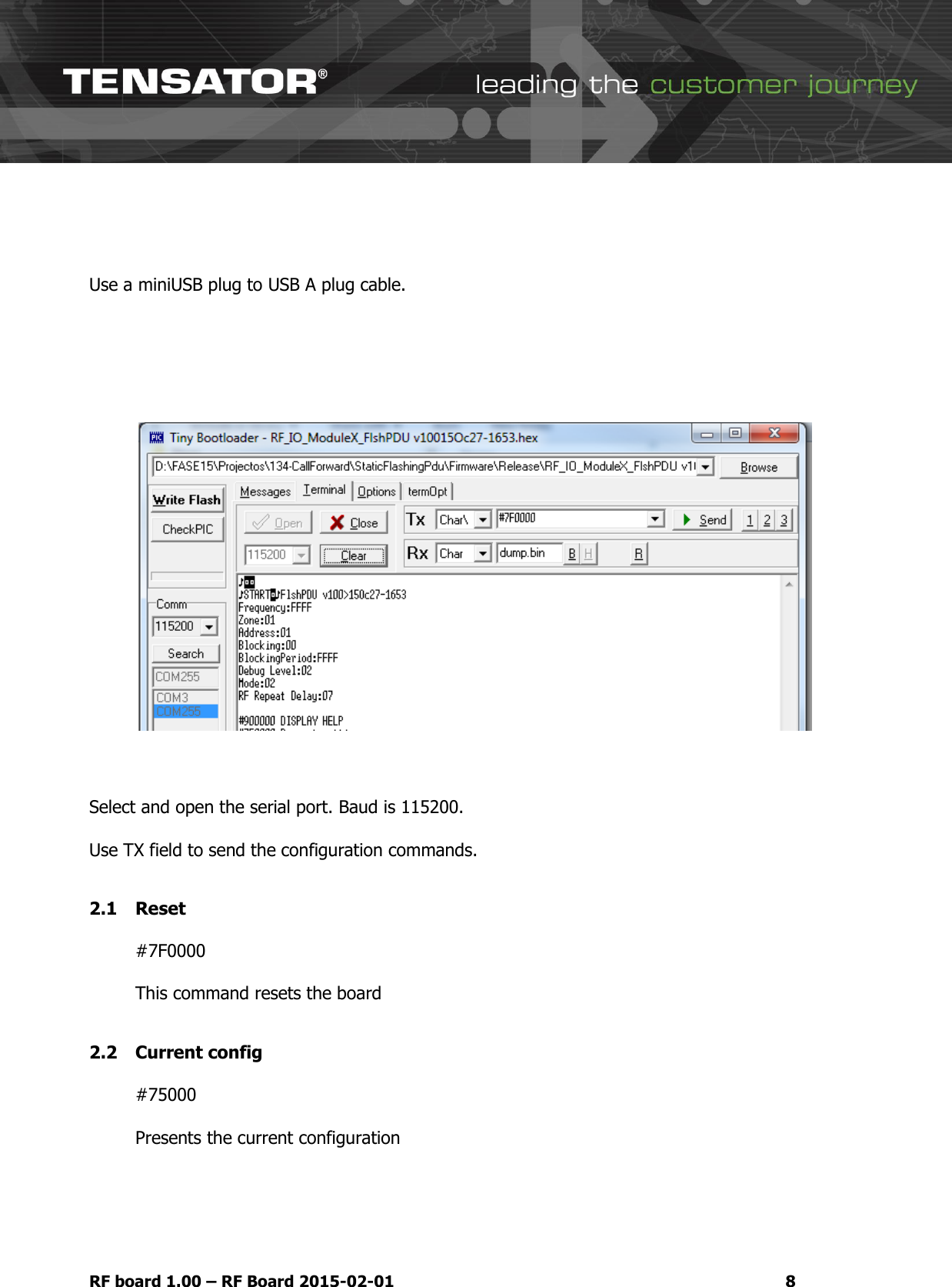
![[Type text] RF board 1.00](https://usermanual.wiki/Tensator/RFIOBRD00/User-Guide-2908566-Page-1.png)