Testo SE and KGaA 2016T330I testo 330i - flue gas analyzer User Manual
Testo AG testo 330i - flue gas analyzer Users Manual
UserManual.wiki
>
Testo SE and KGaA
>
2016T330I User Manual
Users Manual
Navigation menu
Upload a User Manual
Namespaces
Wiki Guide
HTML
PDF
Info
Views
User Manual
Discussion / Help
Navigation

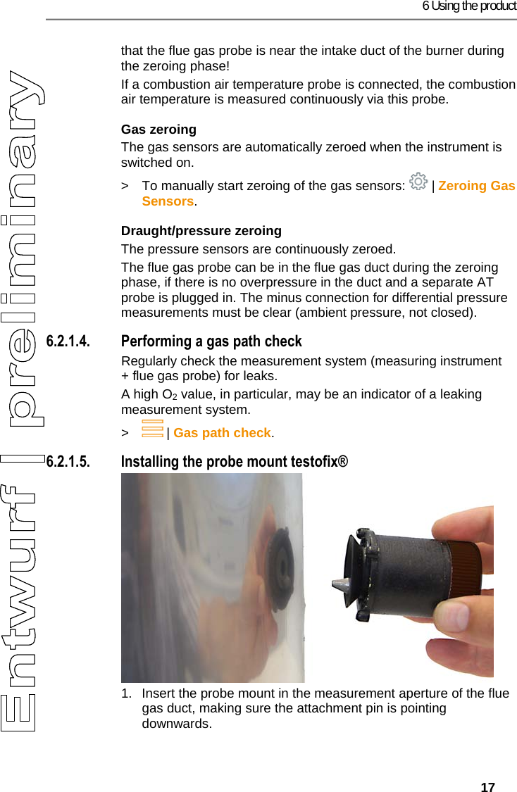
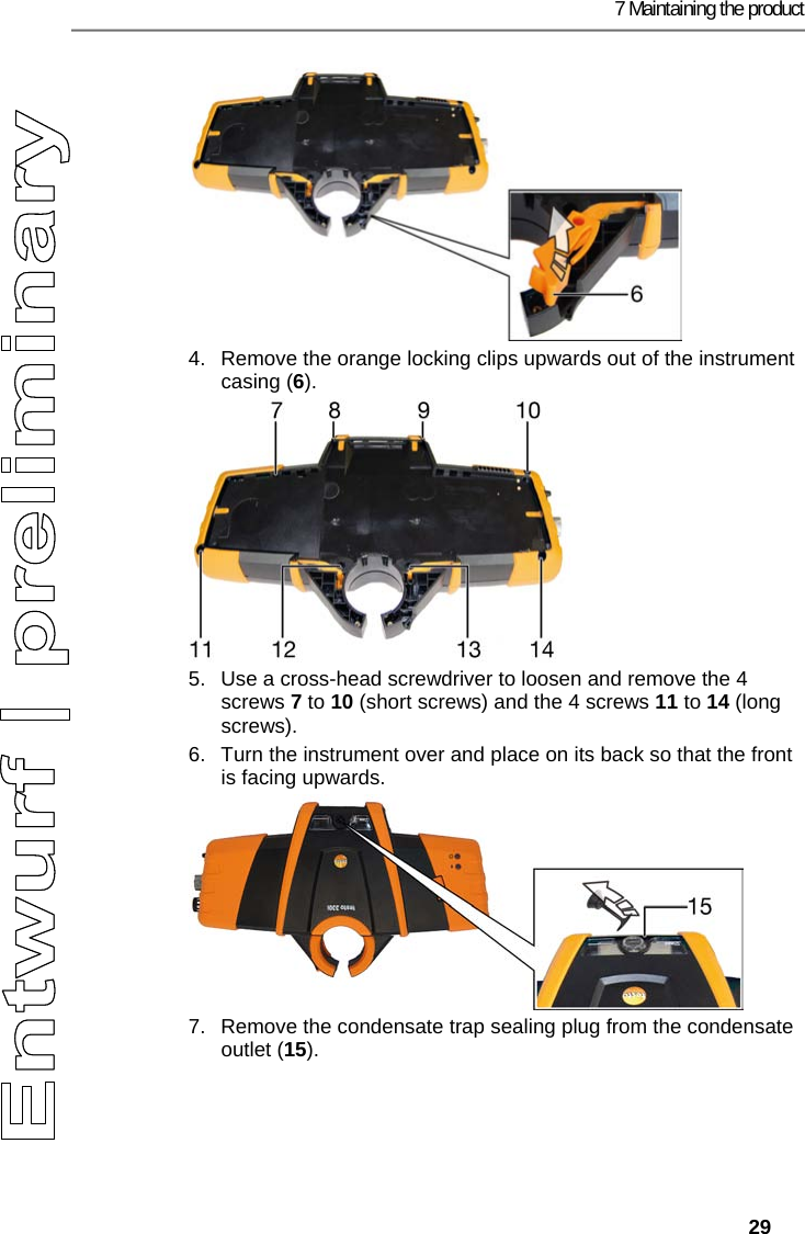
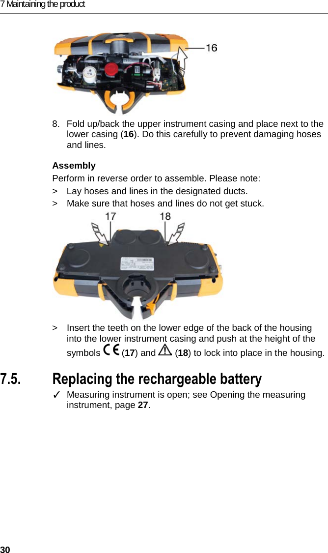
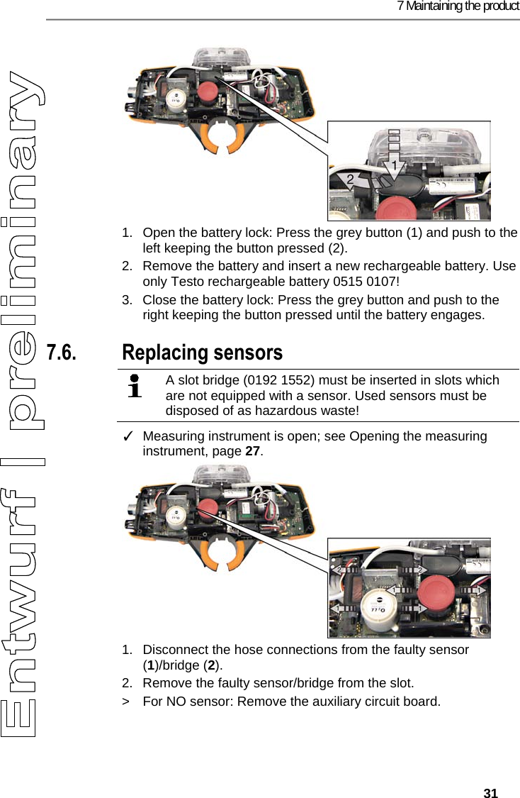
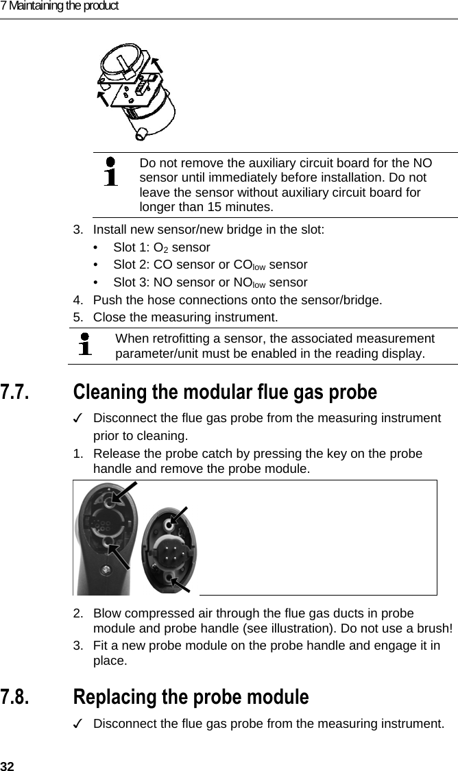
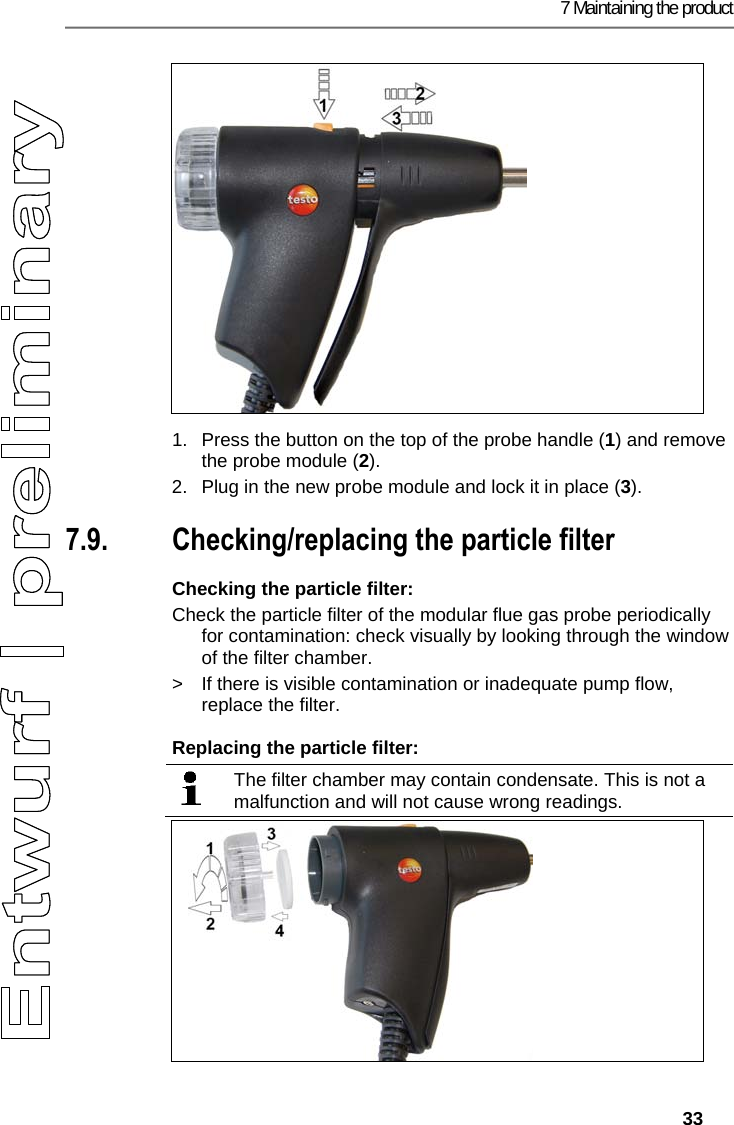
![7 Maintaining the product 34 1. Open the filter chamber: turn slightly anti-clockwise (1). Remove the filter chamber (2). 2. Remove the filter plate (3) and replace it with a new one (4 [0554 3385]). 3. Attach the filter chamber and lock it: turn slightly clockwise. Pos: 60 /TD/Produkt ins tand halten/testo 330 und t esto 350 neu/testo 330/ 350 Instandhaltung Thermoelement wechseln @ 6\mod_1 270039469873_ 79.docx @ 60729 @ 2 @ 1 7.10. Changing the thermocouple 1. Release the probe catch by pressing the key on the probe handle and remove the probe module. 2. Remove the thermocouple plug-in head from the socket using a screwdriver and pull the thermocouple out of the probe shaft. 3. Keep inserting the new thermocouple into the probe shaft until the connection head clicks into place. 4. Fit a new probe module on the handle and engage in place. Pos: 61 /TD/Tipps und Hilf e/testo 330i Firm ware-Update @ 18\mod_14383592 71696_79.docx @ 217194 @ 2 @ 1 7.11. Updating the instrument software At www.testo.com/download-center you can download the current instrument software (firmware) for the testo 330i. ✓ The measuring instrument must be switched off. 1. Plug the measuring instrument mains unit into a mains socket. 2. Press and hold down for 10 s. - Both status LEDs (blue/red) slowly flash alternately. 3. Insert the connecting cable (0449 0047) into the USB port on the measuring instrument, then connect it to the PC. - Your PC identifies the measuring instrument as a removable medium. 4. Copy the new instrument software file (ap330ir.bin) to the identified removable medium. - Both status LEDs (blue/red) quickly flash alternately. This process may take a few minutes. 5. Disconnect the connecting cable from the measuring instrument. - Once the instrument software has been updated, the measuring instrument will automatically reboot and is ready for use again.](https://usermanual.wiki/Testo-SE-and-KGaA/2016T330I/User-Guide-2938749-Page-34.png)