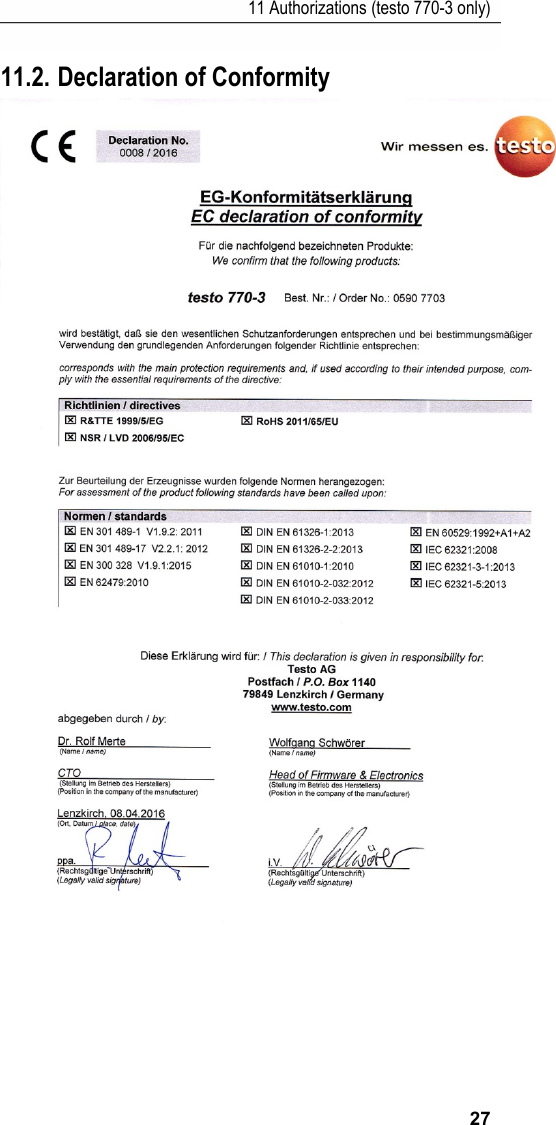
Testo SE and KGaA 2016T770-3 Bluetooth Clamp Meter User Manual
Testo AG Bluetooth Clamp Meter Users Manual
UserManual.wiki
>
Testo SE and KGaA
>
2016T770 3 User Manual
Users Manual
Navigation menu
Upload a User Manual
Namespaces
Wiki Guide
HTML
PDF
Info
Views
User Manual
Discussion / Help
Navigation
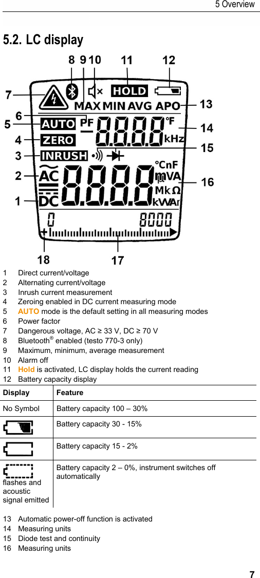
![5 Overview 8 17 Analog display (testo 770-3 only) 18 Indication of polarity in bar chart (testo 770-3 only) 5.3. Control key functions The clamp meter features a rotary switch, as well as 6 control keys, which respond to a brief or a long keypress. In the default setting, the instrument is in AUTO mode when voltage, current, RCDC (resistance, capacitance and diode with continuity) is being measured. Key Brief keypress function (<1 s) Long keypress function (>2 s) Zero adjustment Zeroing when measuring DC current Exit zero adjustment Select Switches between the manual sub-modes of the selected measurement. Back to AUTO mode Min/Max Switches between MAX, MIN and AVG functions Switch off recording mode Inrush If position A is selected, the instrument switches to inrush mode. Reset the inrush measurement if a measurement is already shown on the LC display. Switches back to the mode most recently activated before INRUSH was selected. Illumination Background illumination on/off (testo 770-3) Illumination/Bluetooth Background illumination on/off Bluetooth on/off 5.4. Rotary switch functions Selection Function Switch off Switch the instrument off. Current Activates automatic mode for current, choose between AC/DC. Manual selection of AC/DC with []. Voltage Activates automatic mode for voltage between AC and DC measurement via the test leads and jacks. Manual selection of AC/DC with [].](https://usermanual.wiki/Testo-SE-and-KGaA/2016T770-3/User-Guide-3062539-Page-8.png)
![5 Overview 9 Selection Function RCDC control Automatic mode for resistance, continuity, capacitance and diode test. Manual selection of AC/DC with []. testo 770-3 only Activates the mode for power measurement. Manual selection of active, reactive and apparent power, as well as power measurement for direct current/voltage with []. testo 770-2/-3 only Automatic mode for µA measurement. Manual selection of AC/DC with []. 5.5. Further functions Bluetooth® (testo 770-3 only) > Enable Bluetooth®: press and hold down [] and turn the rotary switch from [OFF] to a function. Then release []. > Disable Bluetooth®: turn rotary switch to [OFF]. HOLD > Activate function: press [HOLD] <1 s. - the current reading is recorded and HOLD is shown on the LC display. > Exit function: press [HOLD] <1 s. - the current measurement is displayed. The Hold function can be used from all measuring modes. MAX/MIN/AVG [] allows for switching between maximum, minimum and the periodic display of AVG values. This function is disabled in the default setting. > Activate function: press [] <1 s. - Max value is displayed. > Display min value and periodic display of AVG values: press [] <1 s each time. > Exit function: press [] >2 s or [HOLD]. This function can be activated in all measuring modes (this function is not available at capacitance measurement with testo 770-1 and testo 770-2). When pressing [] in AUTO AC/DC voltage mode or AUTO AC/DC current measurement mode, the instrument retains the last-selected AC/DC setting. In all other operating states, you can select what you need by briefly pressing the [] key or via the rotary switch itself: • Voltage measurement and measurement with a thermocouple adapter: select](https://usermanual.wiki/Testo-SE-and-KGaA/2016T770-3/User-Guide-3062539-Page-9.png)
![6 Operating the instrument 10 • Current measurement: select • Resistance, continuity, diode and capacitance measurement: select • μA measurement: select (testo 770-3 only). • Power measurement: select (testo 770-3 only). 5.6. Explanation of icons Icon Meaning Attention! Warning about a danger spot, refer to instruction manual Caution! Dangerous voltage, risk of electric shock Application around and removal from HAZARDOUS LIVE conductors is permitted. Continuous double or reinforced insulation complies with category II DIN EN 61140 / IEC 536 The product is certified for the US and Canadian markets, in accordance with the applicable American and Canadian standards. Tested for safety (tested by TÜV Rheinland) Compliance mark for ACMA (Australian Communications and Media Authority) guidelines. This product has been tested to the requirements of CAN/CSA-C22.2 No. 61010-1, second edition, including Amendment 1, or a later version of the same standard incorporating the same level of testing requirements. Bluetooth testo 770-3 only Conformity mark, verifies compliance with the valid EU Directives: EMC Directive (2014/30/EU) with the EN 61326-1 standard, Low-Voltage Directive (2014/35/EU) with the EN 61010-1 standard The instrument complies with the WEEE Directive (2012/16/EU) Pos: 11 /TD/Überschr iften/Elektr. Messgr ößen/7. Gerät bedien en @ 17\mod_1432652368778 _79.docx @ 213261 @ 1 @ 1 6 Operating the instrument Pos: 12 /TD/Produkt verwenden/Elektr. Messgöß en/testo 770 Techno logie @ 18\mod_14437662963 40_79.docx @ 222467 @ @ 1 Different measuring modes can be selected via the rotary switch. When the instrument is in voltage mode [ ], it automatically detects the range and the type of measurement, AC or DC. When the instrument is in current mode [ ], it automatically switches between AC and DC accordingly. When the rotary switch is at the [ ] position, the instrument automatically detects the appropriate measurement. If the instrument is switched to](https://usermanual.wiki/Testo-SE-and-KGaA/2016T770-3/User-Guide-3062539-Page-10.png)
![6 Operating the instrument 11 power mode [ ], it measures active, reactive and apparent power together with the power factor (for sinusoidal signals). All the available measuring modes can also be selected manually. Pos: 13 /TD/Produkt verwenden/Elektr. Messgöß en/testo 770 Gerät bedi enen @ 18\mod_1443766976 623_79.docx @ 222502 @ 22255 @ 1 6.1. Switching the instrument on > Switch on: turn the rotary switch to the required measuring mode. - The instrument switches on. 6.2. Switching the background illumination on/off > To switch on/off: briefly press the [] key. The background illumination switches off automatically within 1 minute. It is possible to switch the background illumination on/off in all measuring modes. 6.3. Switching the instrument off (automatically/manually) Automatically The automatic power-off function (APO) is always enabled as a default setting and is shown on the LC display as APO. If no control key is pressed within 15 min, the instrument switches off automatically. If necessary, the automatic power-off function (APO) can be turned off. > Disable power-off function: press the [HOLD] key and turn the rotary switch from the OFF position to a different position. Once the instrument has switched off, the power-off function is reset to the default setting. Manually > Switch off: turn the rotary switch to the [OFF] position. Pos: 14 /TD/Produkt verwenden/Elektr. Messgöß en/testo 770 Gerät via Ap p bedienen @ 19\mod_145681 6950576_79.doc x @ 232568 @ 2225 @ 1 6.4. Using testo 770-3 with testo Smart Probes App 6.4.1. Establishing Bluetooth® connection (770-3) You need a tablet or smartphone with the testo Smart Probes App already installed on it to be able to establish a Bluetooth connection. You can get the App for iOS instruments in the App Store or for Android instruments in the Play Store. Compatibility: • requires iOS 8.3 or newer / Android 4.3 or newer • requires Bluetooth 4.0 • tested with the following smartphones / tablets: www.testo.com/smartprobesmanuals.html](https://usermanual.wiki/Testo-SE-and-KGaA/2016T770-3/User-Guide-3062539-Page-11.png)
![7 Carrying out a measurement 12 ✓ The testo Smart Probes App is installed on your mobile terminal device and ready for use. > Enable Bluetooth®: press and hold down [] and turn the rotary switch from [OFF] to a function. Then release []. - CONN appears in the display. If the Bluetooth® connection is established, appears in the display and the instrument changes to the set measuring mode. > Disable Bluetooth®: Turn rotary switch to [OFF]. 6.4.2. Transmitting readings ✓ testo 770-3 is switched on and connected to your mobile terminal device via Bluetooth. - The current readings are automatically displayed in the App. 6.4.3. Overview of the App operating controls 1 Choice of applications. 2 Display of connected instruments. 3 Switch between views (list, graphic, table) 4 Settings for measurement. (The menu adjusts depending on the instrument connected and the application selected) 5 Restarts the measuring value recording in graph and table format. 6 Export of the readings 7 Menu options Pos: 15 /TD/Überschr iften/Elektr. Messgr ößen/8. Messung durc hführen @ 18\mod_14459507 15479_79.docx @ 223867 @ 1 @ 1 7 Carrying out a measurement Pos: 16 /TD/Produkt verwenden/Elektr. Messgöß en/testo 770 Prüfung vorbereiten @ 18\mod_14446 36040115_79.doc x @ 223527 @ 2 @ 1 7.1. Preparing for measurement Prior to every measurement, please ensure that the instrument is in perfect condition: • For example, keep an eye out for broken housing or leaking batteries. • Always carry out a function test before using the instrument, see below.](https://usermanual.wiki/Testo-SE-and-KGaA/2016T770-3/User-Guide-3062539-Page-12.png)
![7 Carrying out a measurement 13 • Check that the instrument is functioning perfectly (for example at a known voltage source) before and after every test. • If the safety of the user cannot be guaranteed, the instrument must be switched off and secured to prevent unintentional usage. When connecting the test leads to the test object, always connect the common test lead (COM) to the test object first of all. When disconnecting the test leads, always disconnect the +/- phase test lead first of all. Pos: 17 /TD/Produkt verwenden/Elektr. Messgöß en/testo 770 Strom messung 770 @ 18\mod_14440433 06914_79.docx @ 222943 @ 555 5355 @ 1 7.2. Current measurement WARNING Serious risk of injury to the user and/or destruction of the instrument while measuring current. > Measuring circuit must be de-energized. The measuring instrument may only be used in circuits up to a maximum voltage of 600V. The nominal cross-section of the connection cable must be taken into account in order to ensure safe connection (e.g. via crocodile clips). Strong RFinterference and / or open leadswhen measuring A AC may result in unstable display readings. 7.2.1. Measuring A AC or A DC Automatic measuring mode 1. Switch instrument on: set rotary switch to . - The instrument switches on. - The instrument is in AUTO A mode. 2. Enclose the live conductor and centre it in the jaws. - The instrument automatically detects the A AC or A DC mode. - The measured value is shown on the LC display. For measurements below 3.0 A AC, the automatic AC/DC detection might not work. If that happens, set AC/DC manually. Manual measuring mode ✓ Instrument is in automatic measuring mode AUTO A 1. Exit AUTO A measuring mode: press [] <1 s. 2. Switch between A AC and A DC: press [] <1 s. - The measured value is shown on the LC display. Switch to automatic measuring mode: press [] >1 s. - The instrument is in automatic measuring mode when AUTO is illuminated on the LC display. 7.2.2. Measuring µA AC or µA DC (testo 770/-2/-3 only) Automatic measuring mode 1. Switch instrument on: set rotary switch to . - The instrument switches on.](https://usermanual.wiki/Testo-SE-and-KGaA/2016T770-3/User-Guide-3062539-Page-13.png)
![7 Carrying out a measurement 14 - The instrument is in AUTO µA mode. 2. Connect test leads: black test lead to black jack, red test lead to red jack. Then connect test leads to the test object. - The instrument automatically detects the µA AC or µA DC mode. - The measured value is shown on the LC display. Manual measuring mode ✓ Instrument is in automatic measuring mode AUTO µA. 1. Exit AUTO µA measuring mode: press [] <1 s. 2. Switch between µA AC and µA DC: press [] <1 s. - The measured value is shown on the LC display. Switch to automatic measuring mode: press [] >1 s. - The instrument is in automatic measuring mode when AUTO is illuminated on the LC display. Pos: 18 /TD/Produkt verwenden/Elektr. Messgöß en/testo 770 Spannun gsprüfung @ 18\mod_144 4035909178_79.doc x @ 222668 @ 255 @ 1 7.3. Voltage measurement When measuring AC voltage, the frequency is measured at the same time and shown in the relevant row on the LC display. Automatic measuring mode 1. Switch instrument on: set rotary switch to . - The instrument switches on. - The instrument is in AUTO V mode. 2. Connect test leads: black test lead to black jack, red test lead to red jack. Then connect test leads to the test object. The instrument features a built-in zero crossing detector. When the measured signal (voltage or current) indicates zero crossings, the instrument automatically switches to AC measuring mode. If continuity is indicated, the instrument switches to DC measuring mode. - The measured value is shown on the LC display. Manual measuring mode ✓ Instrument is in automatic measuring mode AUTO V. 1. Exit AUTO V measuring mode: press [] <1 s. 2. Switch between V AC and V DC: press [] <1 s. - The measured value is shown on the LC display. 3. Switch to automatic measuring mode: press [] >1 s. - The instrument is in automatic measuring mode when AUTO is illuminated on the LC display.](https://usermanual.wiki/Testo-SE-and-KGaA/2016T770-3/User-Guide-3062539-Page-14.png)
![7 Carrying out a measurement 15 Pos: 19 /TD/Produkt verwenden/Elektr. Mes sgößen/testo 770 RCDC-Messung @ 18\mod_14446 50011502_79.doc x @ 223562 @ 235355 @ 1 7.4. Measuring resistance, capacitance, continuity and diode test WARNING Serious risk of injury to the user and/or destruction of the instrument during resistance testing. > Test object must be de-energized. External voltages will distort the measurement result. 7.4.1. testo 770-1/-2 Manual measuring mode 1. Switch instrument on: set rotary switch to . - The instrument is switched on. 2. Connect test leads: black test lead to black jack, red test lead to red jack. Then connect test leads to the test object. - The instrument is in Ω measuring mode. 3. Switch between resistance, capacitance, continuity and diode test: press [] <1 s. - The measured value is shown on the LC display. 7.4.2. testo 770-3 Automatic measuring mode Automatic detection for resistance/capacitance in the following range: • 0.0 ohms to 6.000 mohms • 0.500 nF to 600.0 µF Change to manual measuring mode for the remaining measuring range. 1. Switch instrument on: set rotary switch to . - The instrument is switched on. 2. Connect test leads: black test lead to black jack, red test lead to red jack. Then connect test leads to the test object. - The instrument is in AUTO RCDC measuring mode. - The instrument detects resistance, continuity, diode and capacitance and automatically adjusts the measuring range. - The measured value is shown on the LC display. Manual measuring mode 3. Disable AUTO RCDC measuring mode: press [] <1 s. 4. Switch between resistance, capacitance, continuity and diode test: press [] <1 s. - The measured value is shown on the LC display. > Switch back to AUTO mode: press [] >2 s.](https://usermanual.wiki/Testo-SE-and-KGaA/2016T770-3/User-Guide-3062539-Page-15.png)
![7 Carrying out a measurement 16 Pos: 20 /TD/Produkt verwenden/Elektr. Messgöß en/testo 770 Wi rk_Blind_Scheinleistu ng @ 18\mod_1445495386810 _79.docx @ 223742 @ 2 @ 1 7.5. Power measurement (testo 770-3 only) For the power measurement, two measurements are carried out at the same time. The voltage of the measurement object is measured via the COM jack, V input jack and using two test leads. The current of the measurement object must be measured using the clamp meter. From these two factors, the instrument automatically calculates the different types of power, as well as the power factor. 1. Switch instrument on: set rotary switch to . - The instrument switches on. - The instrument is in the mode for power measurement with alternating current/voltage 2. Enclose the live conductor and centre it in the jaws. 3. Connect test leads: black test lead to black jack, red test lead to red jack. Then connect test leads to the test object. 4. The instrument displays the active power in w(atts) and the power factor (PF). The instrument requires approx. 5 s for the reading to be displayed. An updated reading is displayed after approx. 5 s. 5. Switch between active power, apparent power, reactive power and power measurement for direct current/voltage: press [] <1 s. Pos: 21 /TD/Produkt verwenden/Elektr. Messgöß en/testo 770 Frequenz messung @ 18\mod_144411 0407551_79.doc x @ 223197 @ 2 @ 1 7.6. Frequency measurement The frequency is displayed automatically during an A AC or V AC measurement. The following minimum values are necessary for correct display of frequency with voltage and/or current measurement: Voltage: 200 mV Current: 1.5% of the measuring range Pos: 22 /TD/Produkt verwenden/Elektr. Messgöß en/testo 770 Tempera turmessung @ 18\mod_1444 110824037_79.doc x @ 223232 @ 25 @ 1 7.7. Temperature measurement (optional) (testo 770-2/-3 only) A thermocouple adapter (0590 0021) is optionally available for measuring temperature. Before using the thermocouple adapter, please carefully read through the relevant section relating to the thermocouple adapter in the documentation. Familiarize yourself with the product before using it. Pay particular attention to the safety instructions and warning advice in order to prevent injuries and damage to the product. In this section, it is assumed that you are familiar with the contents of the documentation relating to the thermocouple adapter. Carrying out temperature measurement ✓ A thermocouple is attached to the thermocouple adapter. 1. Switch instrument on: set rotary switch to . - The instrument switches on. - The instrument is in AUTO V mode 2. Connect the thermocouple adapter to the instrument: plug the adapter into the jack. Ensure correct polarity!](https://usermanual.wiki/Testo-SE-and-KGaA/2016T770-3/User-Guide-3062539-Page-16.png)
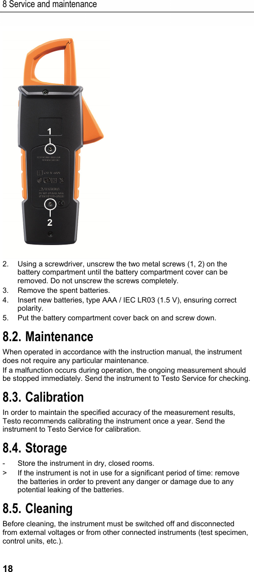
![8 Service and maintenance 17 - The thermocouple adapter switches on automatically. 3. Activate temperature measurement: press [] >2 s. - The measured values are shown on the LC display in °C and °F. Pos: 23 /TD/Produkt verwenden/Elektr. Messgöß en/testo 770 Einscha ltstrom @ 18\mod_14441 18904937_79.doc x @ 223267 @ 2 @ 1 7.8. Inrush current (INRUSH) The inrush function is an approximation function. This means that readings can differ from one another. 1. Switch instrument on: set rotary switch to . - The instrument switches on. - The instrument is in AUTO A mode. 2. Enclose the live conductor and centre it in the jaws. 3. Activate inrush current calculation: press [] <1 s. - The measured value is shown on the LC display. 4. Restart inrush current calculation: press [] <1 s. - The measured value is shown on the LC display. 5. Exit inrush current calculation and switch back to AUTO mode: press [] >2 s. Pos: 24 /TD/Überschr iften/Elektr. Messgr ößen/9. Wartung und Pf lege @ 17\mod_14340271359 86_79.docx @ 213637 @ 1 @ 1 8 Service and maintenance Pos: 25 /TD/Produkt ins tand halten/Elektr. Messgrößen/testo 770 W artung @ 18\mod_14437035771 11_79.docx @ 222427 @ 22222 @ 1 8.1. Replacing the batteries The batteries need to be replaced when the battery icon appears on the LC display. ✓ The instrument is switched off. 1. Disconnect the instrument from the test leads and make sure that the instrument is not enclosing any live cable.](https://usermanual.wiki/Testo-SE-and-KGaA/2016T770-3/User-Guide-3062539-Page-17.png)
![9 Technical data 20 Pos: 28 /TD/Leistungsb eschreibung/Tec hnische Daten/Elek tr. Messgrößen/testo 770 _Spezifikation 77 0-1_2 @ 18\mod_144412070 9404_79.docx @ 223337 @ 33 @ 1 9.2. More technical data 9.2.1. testo 770-1/-2 Feature Measuring range1 Resolution Accuracy DC voltage 4.000 V 40.00 V 400.0 V 600 V 1 mV 10 mV 100 mV 1 V ± (0.8% of meas. val. + 3 digits) AC voltage2,3,4 4.000 V 40.00 V 400.0 V 600 V 1 mV 10 mV 100 mV 1 V ± (1.0% of meas. val. + 3 digits) DC current - jaws [A] - jack [µA] (testo 770-2) 400 A 400 µA 0.1 A 0.1 µA ± (2.0% of meas. val. + 5 digits) ± (1.5% of meas. val. + 5 digits) AC current3 - jaws [A]5 - jack [µA] (testo 770-2)2,4 400 A 400 µA 0.1 A 0.1 µA ± (2.0% of meas. val. + 5 digits) ± (1.5% of meas. val. + 5 digits) Resistance 400.0 Ohm 4.000 kOhm 40.00 kOhm 400.0 kOhm 4.000 MOhm 40.00 MOhm 0.1 Ohm 1 Ohm 10 Ohm 100 Ohm1 kOhm 10 kOhm ± (1.5% of meas. val. + 3 digits) Continuity alarm <0 to 30 Ohm Diode test yes (0 to 2.5 V) Capacity 51.20 nF6 0.01 nF ± 10% typically 1 The lower measuring ranges are only specified from 5% (does not apply to DC current / AC current measurements with the current probe) 2 Signal bandwidth 40 Hz to 1 kHz 3 In the case of a mixed signal (AC + DC), only the purely AC component is taken into account 4 As the frequency increases (over 400 Hz), the accuracy deteriorates +/- (1.5% of m.v. + 3 digits) for 400Hz to 750Hz / +/- (2.0% of m.v. + 3digits) for 750Hz to 1kHz 5 Frequency of AC current up to 400 Hz 6 Specification is valid for capacitances > 10 nF](https://usermanual.wiki/Testo-SE-and-KGaA/2016T770-3/User-Guide-3062539-Page-20.png)
![9 Technical data 21 Feature Measuring range1 Resolution Accuracy 512.0 nF 0.01 nF ± (1.5% of meas. val. + 5 digits) 5.120 µF 0.001 µF ± (1.5% of meas. val. + 5 digits) 51.20 µF 0.01 µF ± 10% typically 100.0 µF (15 s)7 0.1 µF ± 10% typically Temperature with adapter (testo 770-2)8 -20 to 500 °C 0.2 °C -20 to 0 °C: +/- 2 °C 0 °C to 100 °C: +/- 1 °C100 °C to 250 °C: +/-1.5% >250 °C: +/-2% Figures correspond to +23 °C ± 5 °C at <80% rel. humidity. Temperature coefficient: 0.15 x specified accuracy per 1 °C (<18 °C and >28 °C) Pos: 29 /TD/Leistungsb eschreibung/Tec hnische Daten/Elek tr. Messgrößen/testo 770 _Spezifikation 77 0-3 @ 18\mod_14441206584 07_79.docx @ 223302 @ 3 @ 1 9.2.2. testo 770-3 Feature Measuring range9 Resolution Accuracy DC voltage 600 mV 6.000 V 60.00 V 600.0 V 0.1 mV 1 mV 10 mV 100 mV ± (0.8% of meas. val. + 3 digits) AC voltage10,11,12 600 mV 6.000 V 60.00 V 600.0 V 0.1 mV 1 mV 10 mV 100 mV ± (1.0% of meas. val. + 3 digits) DC current - jaws [A] - jack [μA] 600 A 600 μA 0.1 A 1 μA ± (2.0% of meas. val. + 5 digits) ± (1.5% of meas. val. + 5 digits) 7 Maximum measurement duration is 15 s 8 Does not include the measurement error of the temperature probe. The specified accuracy is the sum total of the measurement errors of the thermocouple adapter and the testo 770. 9 The lower measuring ranges are only specified from 5% (does not apply to DC current / AC current measurements with the current probe) 10 Signal bandwidth 40 Hz to 1 kHz 11 In the case of a mixed signal (AC + DC), only the purely AC component is taken into account 12 As the frequency increases (over 400 Hz), the accuracy deteriorates +/- (1.5% of m.v. + 3 digits) for 400Hz to 750Hz / +/- (2.0% of m.v. + 3digits) for 750Hz to 1kHz](https://usermanual.wiki/Testo-SE-and-KGaA/2016T770-3/User-Guide-3062539-Page-21.png)
![9 Technical data 22 Feature Measuring range9 Resolution Accuracy AC current11 - jaws [A]13 - jack [μA]10,12 600 A 600 μA 0.1 A 0.1 μA ± (2.0% of meas. val. + 5 digits) ± (1.5% of meas. val. + 5 digits) Resistance 60.00 Ohm 600.0 Ohm 6.000 kOhm 60.00 kOhm 600.0 kOhm 6.000 MOhm60.00 MOhm 0.01 Ohm 0.1 Ohm 1 Ohm 10 Ohm 100 Ohm 1 kOhm 10 kOhm ± (1.5% of meas. val. + 3 digits) Continuity alarm 0 to 30 Ohm Diode test yes (0 to 2.5 V) Power measurement Power factor: ±5% ±5 digits, for current strength > 10 A ±10% ±5 digits typical, for current strength between > 2 A and < 10 A Power: ±10% current strength > 10 A ±15% typical, for current strength < 10 A Capacitance measurement 6.000 nF14 0.001 nF ± (10% of meas. val. + 25 digits) 60.00 nF 0.01 nF ± (2% of meas. val. + 10 digits) 600.0 nF 0.1 nF ± (1.5% of meas. val. + 5 digits) 6.000 µF 0.001 µF ± (1.5% of meas. val. + 5 digits) 60.00 µF 0.01 µF ± (1.5% of meas. val. + 5 digits) 600.0 µF 0.1 µF ± (2% of meas. val. + 10 digits) 6.000 mF 1.0 µF ± 10% typically 60.00 mF15 10.0 µF ± 10% typically 13 Frequency of AC currents up to 400 Hz 14 Accuracy valid for capacitance values >2 nF 15 Maximum measurement duration is 13.2 s](https://usermanual.wiki/Testo-SE-and-KGaA/2016T770-3/User-Guide-3062539-Page-22.png)