Texa S p A ET17 VEHICLE DIAGNOSTIC SYSTEM User Manual
Texa S.p.A. VEHICLE DIAGNOSTIC SYSTEM
UserManual.wiki
>
Texa S p A
>
ET17 User Manual
User Manual
Navigation menu
Upload a User Manual
Namespaces
Wiki Guide
HTML
PDF
Info
Views
User Manual
Discussion / Help
Navigation
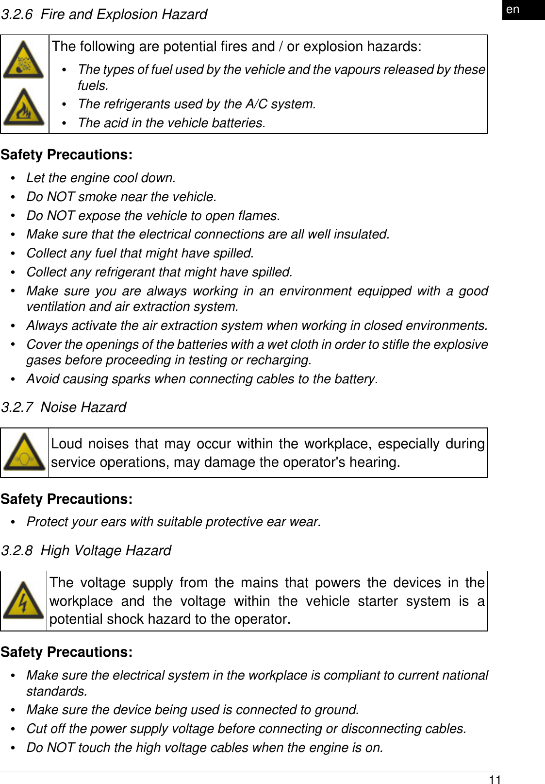
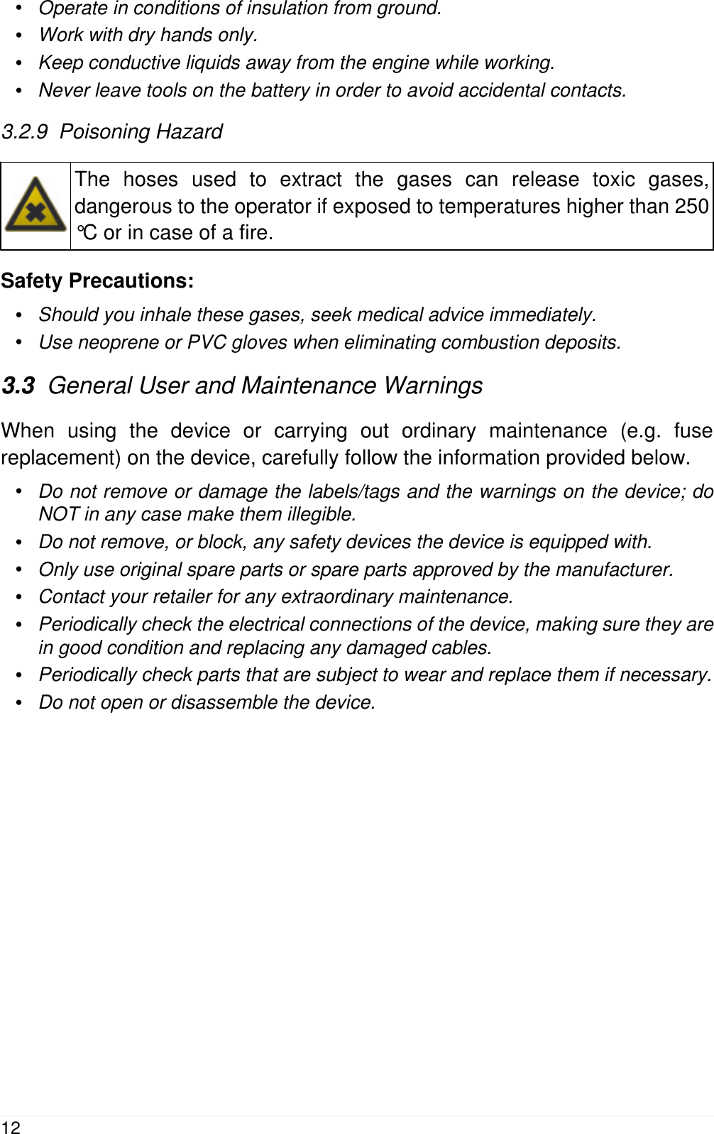
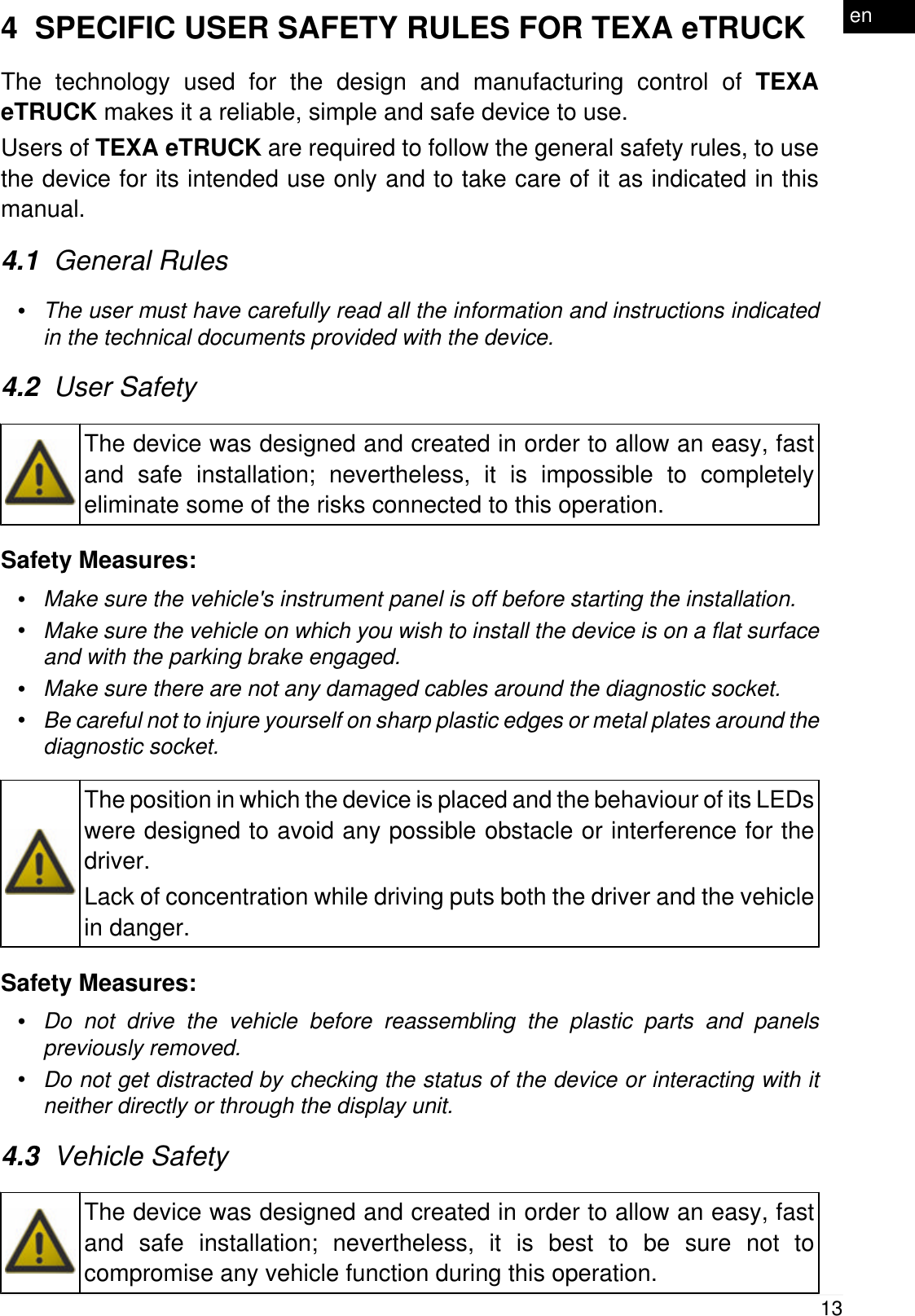
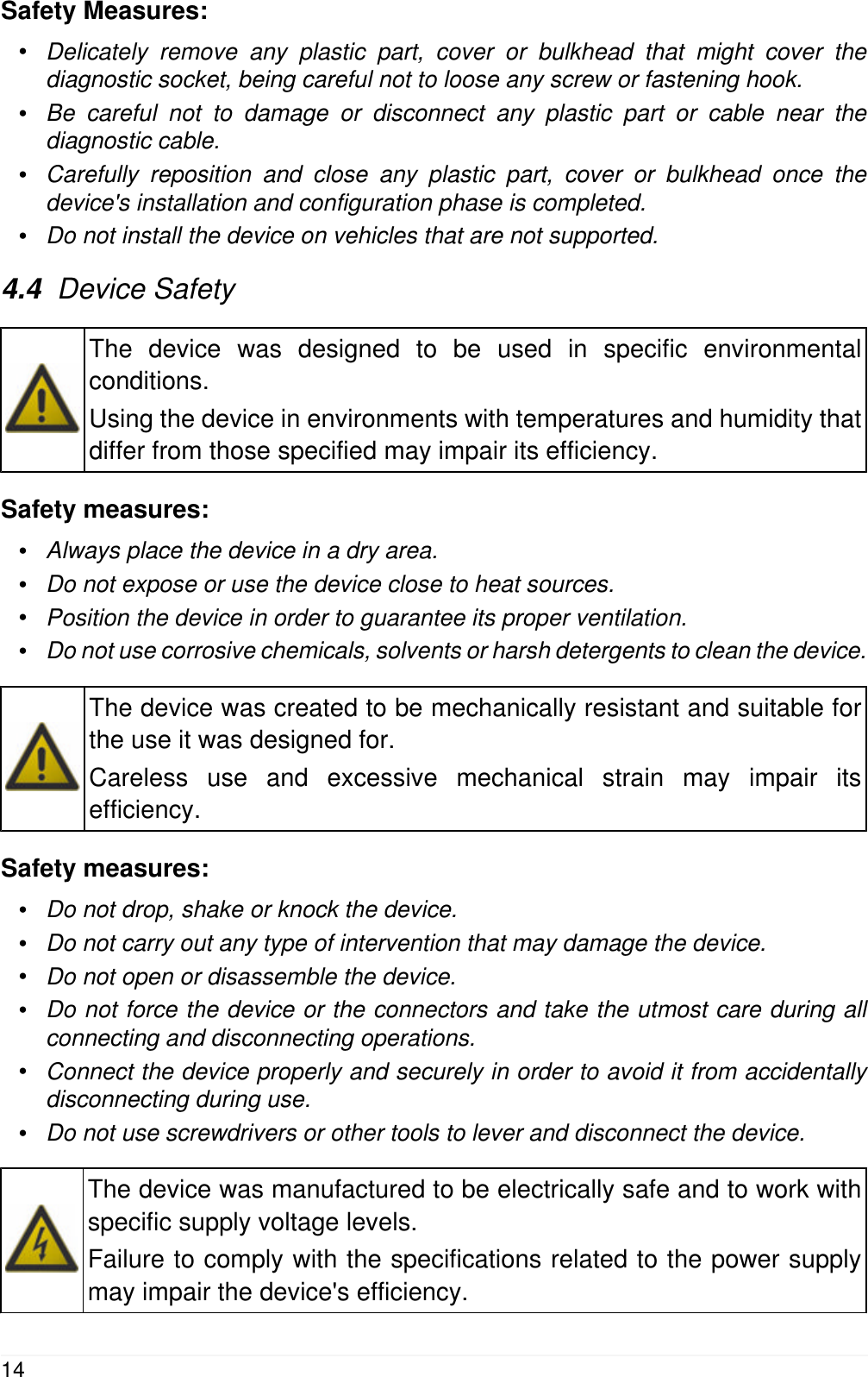
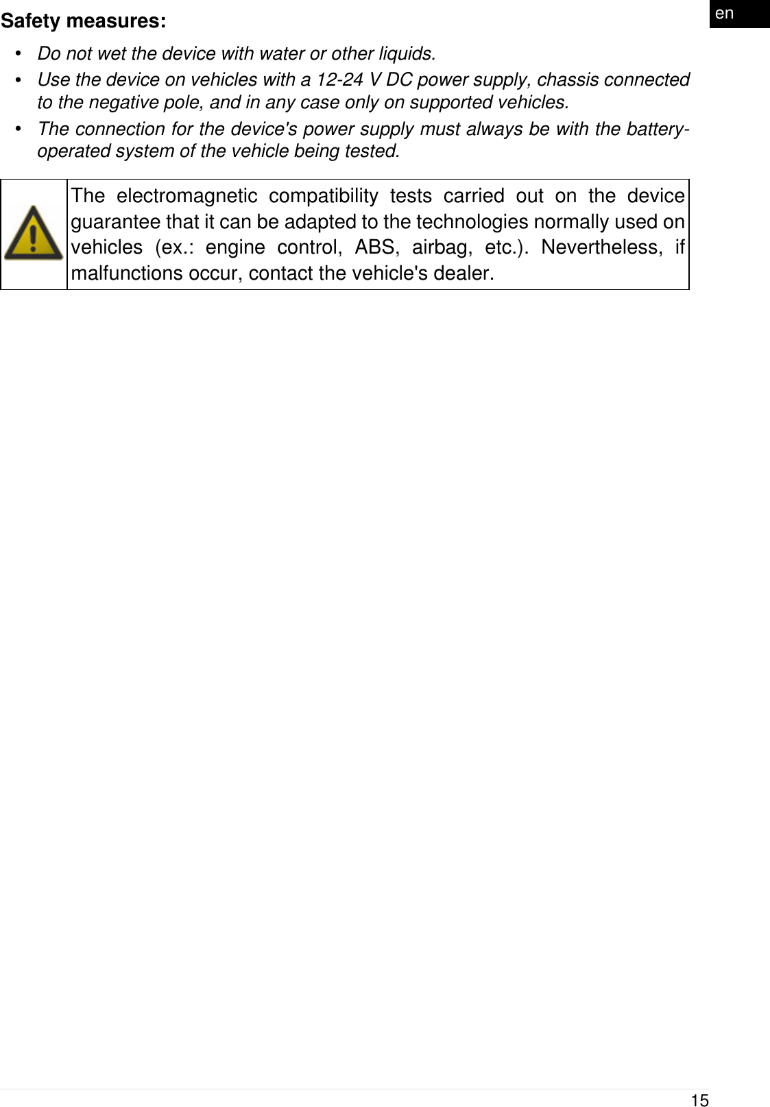
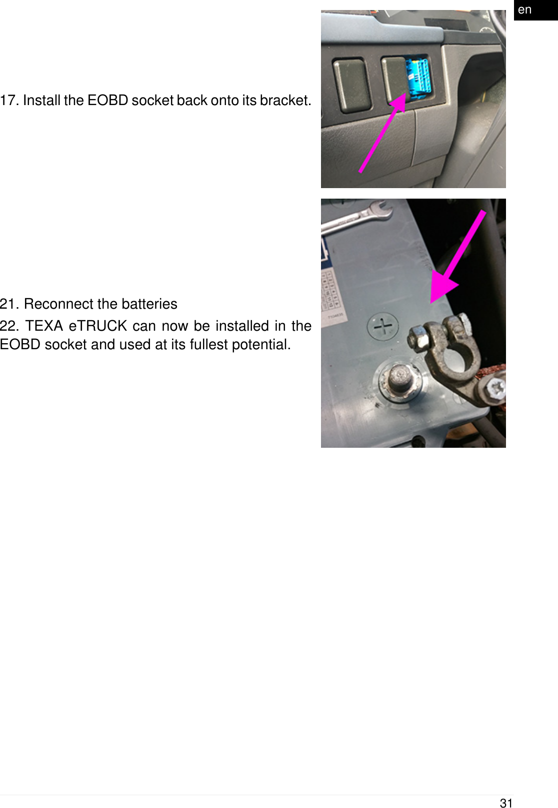
![Dimensions in [mm]Weight 15 gDirectives RED 2014 / 53 / EUROHS 2011 / 65 / EUProduct standardsEN 301 489-1 V2.1.1EN 301 489-17 3.1.1EN 300 328 V2.1.1EN 62311:2008EN 60950-1:2006 / A11+A1+A12+AC:2001+A2:2013ISO 7637-1:2002ISO 7637-2:2011Regulations UN / ECE R1022](https://usermanual.wiki/Texa-S-p-A/ET17/User-Guide-3863884-Page-22.png)