Texa S p A NWNNTX VEHICLE DIAGNOSTIC SYSTEM User Manual
Texa S.p.A. VEHICLE DIAGNOSTIC SYSTEM
User Manual


2

SUMMARY
Introduction............................................................7
ABOUT THE MANUAL...........................................9
1 LEGEND OF THE SYMBOLS USED..............10
2 GLOSSARY....................................................11
3 GENERAL SAFETY REGULATIONS.............12
3.1 Glossary.............................................................12
3.2 Operator Safety Regulations..............................12
3.2.1 General Safety Regulations....................................12
3.2.2 Risk of Asphyxiation...............................................13
3.2.3 Risk of Impact and Crushing...................................13
3.2.4 Hazards Caused by Moving Parts..........................14
3.2.5 Risk of Burning or Scalding....................................14
3.2.6 Fire and Explosion Hazard.....................................15
3.2.7 Noise Hazard..........................................................16
3.2.8 High Voltage Hazard...............................................16
3.2.9 Poisoning Hazard...................................................17
3.3 General User and Maintenance Warnings.........18
4 NAVIGATOR NANO USER SAFETY..............19
4.1 Glossary.............................................................19
3
en

4.2 General Rules...............................................19
4.3 Operator Safety............................................20
4.4 Tool Safety...................................................21
5 ENVIRONMENTAL INFORMATION..........23
6 OPERATION OF THE TOOL RADIO
DEVICES........................................................24
7 NORMATIVE INFORMATION...................25
8 INTRODUCTION.......................................26
9 DESCRIPTION..........................................27
9.1 Image of the device......................................27
9.2 Technical Features.......................................28
10 HOW TO USE THE DEVICE...................30
10.1 Location of the OBD Socket.......................31
10.2 Powering the Device...................................35
10.2.1 Powering the Device via the OBD Socket
....................................................................................35
10.2.2 Power Directly from Battery............................36
10.2.3 Power Ssupply Through Lighter Cable...........39
10.3 Recharging the Internal Battery..................40
10.4 How to Communicate with the Viewing Unit
..............................................................................41
10.4.1 Connecting via Bluetooth ..............................42
4

10.4.2 Connection via USB..............................................43
10.5 Blink Code........................................................44
10.6 Connecting to the Control unit..........................45
10.6.1 LED Light..............................................................46
10.7 Pass-Thru.........................................................47
10.8 Self-diagnosis...................................................49
11 MAINTENANCE............................................50
12 SOLUTIONS TO PROBLEMS......................51
13 LEGAL NOTICES..........................................53
5
en

6

NAVIGATOR NANO TECHNICAL MANUAL
Introduction
Dear Customer,
We would like to thank you for choosing a TEXA product for your
workshop.
We are certain that you will get the greatest satisfaction from it
and receive a great deal of help in your work.
Please read through the instructions in this manual carefully and
keep it for future reference.
Reading and understanding the following manual will help you to
avoid damage or personal injury caused by improper use of the
product to which it refers.
TEXA S.p.A reserves the right to make any changes deemed
necessary to improve the manual for any technical or marketing
requirement; the company may do so at any time without prior
notice.
This product is intended for use by technicians specialized in the
automotive field only. Reading and understanding the information
in this manual cannot replace adequate specialized training in this
field.
The sole purpose of the manual is to illustrate the operation of the
product sold. It is not intended to offer technical training of any
kind and technicians will therefore carry out any interventions
under their own responsibility and will be accountable for any
damage or personal injury caused by negligence, carelessness,
or inexperience, regardless of the fact that a TEXA S.p.A. tool has
been used based on the information within this manual.
Any additions to this manual, useful in describing the new
versions of the program and new functions associated to it, may
be sent to you through our TEXA technical bulletin service.
7
en

This manual should be considered an integral part of the
product to which it refers. In the case it is resold the original
buyer is therefore required to forward the manual to the new
owner.
Reproduction, whole or in part, of this manual in any form
whatsoever without written authorization from the producer is
strictly forbidden.
© copyright and database rights 2011. The material
contained in this document is protected by copyright and
database rights. All rights reserved according to law and
international agreements.
8

ABOUT THE MANUAL
In this document the terms "tool" and "device" refer to the
purchased product, subject of this manual.
Any other specific term is explained in the text.
This manual is divided into the following chapters:
1. Legend of the Symbols: provides the description of the symbols
used in the manual.
2. Glossary: provides the meaning of the technical terms used in the
manual.
3. General Safety Rules: provides important information concerning
the safety of the operator and its workplace.
4. Specific Safety Rules: provides important information concerning
the safety of the operator in relation to the use of the product.
5. Environmental information: provides indications related to the
disposal of the purchased tool/device.
6. Operation of the Radio Devices: provides information concerning
the wireless connectivity of the tool/device.
7. Normative information: reports the declaration of conformity of
the tool/device
8. Description: describes the tool/device, the technical features, the
equipment.
9. Operation: explains all the functions and operation modes of the
tool/device.
10. Maintenance: provides indications on the maintenance of the tool/
device.
11. Solutions to problems: suggests "what to do when... " and gives
information on our client help service.
12. Legal Notes: provides indications related to the guarantee of the
purchased tool/device.
9
en
1 LEGEND OF THE SYMBOLS USED
The symbols used in the manual are described in this chapter.
Asphyxiation Risk
Explosion Risk
High Voltage Hazard
Fire / Burn risk
Poisoning Hazard
Corrosive Substances Risk
Noise Hazard
Moving Parts Risk
Crushing Risk
General Risk
Important information
10

2 GLOSSARY
This chapter provides the meaning of the technical terms
used in the manual:
•Diagnosis/diagnostic socket: female connector mounted on the
vehicle that allows the connection with the control unit of the
vehicle.
•OBD socket: diagnosis socket specific for the OBD protocol.
•Diagnosis/diagnostic connector: male connector mounted on
the diagnosis tool or as end part of a cable to be connected to the
diagnosis tool.
•OBD connector: diagnosis connector specific for the OBD
protocol.
•Diagnosis/diagnostic cable: cable that allows connecting the
diagnosis cable to the diagnosis socket.
•OBD cable: diagnosis cable specific for the OBD protocol.
•Display unit: device equipped with a screen (PC, mobile device,
etc.) on which the special software is mounted that allows
communicating with the tool, configuring it, processing and
displaying the data collected by it.
•Device connector: USB connector used to connect to the device.
•Host connector: USB connector used to connect to the display
unit.
11
en

3 GENERAL SAFETY REGULATIONS
3.1 Glossary
•Operator: qualified individual, in charge of using the device/tool.
•Machine/device/tool: the product purchased.
•Workplace: the place where the operator must carry out her/his
work.
3.2 Operator Safety Regulations
3.2.1 General Safety Regulations
•The operator must be completely clear-headed and sober when
using the device; taking drugs or alcohol before or when operating
the device is strictly forbidden.
•The operator must not smoke during device operation.
•The operator must carefully read all the information and
instructions in the technical documents provided with the device.
•The operator must follow all the instructions provided in the
technical documents.
•The operator must always watch over the device during the various
operating phases.
•The operator must make sure she/he is working in environment
which is suitable for the operations that must be carried out.
•The operator must report any faults or potentially hazardous
situation in connection with the workplace or the device.
•The operator must carefully follow the safety regulations required
for the workplace in which she/he is working and required by the
operations she/he has been asked to carry out.
12
3.2.2 Risk of Asphyxiation
Exhaust gas from internal combustion engines,
whether they may be petrol or diesel, are hazardous
to your health and can cause serious harm to your
body.
Safety Precautions:
•The workplace must be equipped with an adeguate ventilation and
air extraction system and must be in compliance with standards
according to current national laws.
•Always activate the air extraction system when working in closed
environments.
3.2.3 Risk of Impact and Crushing
The vehicles which are undergoing A/C system
recharging operations and the devices, must be
properly blocked using the specific mechanical
brakes/blocks, while being service.
Safety Precautions:
•Always make sure that the vehicle is in neutral gear (or that it is set
in parking position in case of a vehicle equipped with automatic
transmission).
•Always activate the hand brake or parking brake on the vehicle.
•Always block the wheels on the vehicle with the specific
mechanical blocks.
•Make sure the device is stable, on a flat surface and the wheels
are locked with the specific brakes.
13
en
3.2.4 Hazards Caused by Moving Parts
Vehicle engines include parts that move, both while
running and not running (eg: the cooling fan is
controlled by a thermal switch in connection with the
coolant temperature and become activated even
when the vehicle is off), that can injure the operator.
Safety Precautions:
•Keep hands away from moving parts.
•Disconnect the engine cooling fan each time the engine you are
working on is still hot. This will avoid the fan from becoming
activated unexpectedly even when the engine is off.
•Do not wear ties, loose clothes, wrist jewellery or watches when
working on a vehicle.
•Keep connection cables, probes and similar devices away from the
moving parts of the engine.
3.2.5 Risk of Burning or Scalding
The parts that are exposed to high temperatures in
engines that are moving or have just stopped could
burn the operator.
Remember that catalytic mufflers reach very high
temperatures, able to cause serious burns or even
start fires.
Acid in the vehicle batteries is another potential
hazard.
Safety Precautions:
•Protect your face, hands, and feet by using suitable protection.
•Avoid contact with hot surfaces, such as spark plugs, exhaust
pipes, radiators and connections within the cooling system.
•Make sure there are no oil stains, rags, paper or other inflammable
material near the muffler.
•Avoid splashing electrolyte on skin, eyes and clothes, as it is a
corrosive and highly toxic compound.
14

3.2.6 Fire and Explosion Hazard
The following are potential fires and/or explosion
hazards:
•The types of fuel used by the vehicle and the vapours
released by these fuels.
•The refrigerants used by the A/C system.
•The acid in the vehicle batteries.
Safety Precautions:
•Let the engine cool.
•Do NOT smoke near the vehicle.
•Do NOT expose the vehicle to open flames.
•Make sure that the electrical connections are all well insulated.
•Collect any fuel that might have spilled.
•Collect any refrigerant that might have spilled.
•Make sure you are always working in an environment equipped with a
good ventilation and air extraction system.
•Always activate the air extraction system when working in closed
environments.
•Cover the openings of the batteries with a wet cloth in order to stifle the
explosive gases before proceeding in testing or recharging.
•Avoid causing sparks when connecting cables to the battery.
15
en
3.2.7 Noise Hazard
Loud noises that may occur within the workplace,
especially during service operations may damage the
operator's hearing.
Safety Precautions:
•Protect your ears with suitable protective ear wear.
3.2.8 High Voltage Hazard
The voltage supply from the mains that powers the
devices in the workplace and the voltage within the
vehicle starter system is a potential shock hazard to the
operator.
Safety Precautions:
•Make sure the electrical system in the workplace is compliant to current
national standards.
•Make sure the device being used is connected to ground.
•Cut off the power supply voltage before connecting or disconnecting
cables.
•Do NOT touch the high voltage cables when the engine is on.
•Operate in conditions of insulation from ground.
•Work with dry hands only.
•Keep conductive liquids away from the engine while working.
•Never leave tools on the battery in order to avoid accidental contacts.
16

3.2.9 Poisoning Hazard
The hoses used to extract the refrigerants can release
toxic gases, dangerous to the operator if exposed to
temperatures higher than 250 °C or in case of a fire.
Safety Precautions:
•Contact a doctor immediately should you inhale these gases.
•Use neoprene or PVC gloves when eliminating combustion deposits.
17
en

3.3 General User and Maintenance Warnings
When using the device or carrying out scheduled maintenance
(eg. fuse replacement) on the device, carefully follow the
information provided below.
•Do not remove or damage the labels/tags and the warnings on the
device; do NOT in any case make them illegible.
•Do not remove, or block, any safety devices the device is equipped with.
•Only use original spare parts or spare parts approved by the
manufacturer.
•Contact your retailer for any non-scheduled maintenance.
•Periodically check the electrical connections of the device, making sure
they are in good condition and replacing any damaged cables.
•Check parts that are subject to wear periodically and replace if
necessary.
•Do not open or disassemble the device.
18

4 NAVIGATOR NANO USER SAFETY
The technology used for the design and inspection of the
manufacture of the NAVIGATOR NANO diagnostic tools, make
them reliable, simple and safe to use.
Personnel in charge of using the diagnostic tools is required to
follow the general safety regulations and use the NAVIGATOR
NANO devices for their intended use only. Furthermore, they are
required to carry out the maintenance as described in this manual.
4.1 Glossary
Operator: qualified person responsible for using the diagnosis
tool.
Tool/device: any NAVIGATOR NANO device.
4.2 General Rules
•The operator must have basic knowledge in mechanics, automotive, car
repairs and potential dangers that can occur during the auto-diagnosis
operations.
•The operator must carefully read all the information and instructions in
the technical documents provided with the tool.
19
en

4.3 Operator Safety
Airbags inflate with great force; a tool placed in their
expansion area may be projected towards the
occupants of the vehicle causing serious harm.
Safety Measures:
•DO NOT position the tool in the airbag expansion area.
Some auto-diagnosis operations allow enabling/
disabling certain actuators and safety systems in the
vehicle.
Safety Measures:
•Do not allow unqualified personnel using the tool, in order to avoid
accidents to people or damages to the tool or to electronic systems of
the vehicle to which it is connected.
•Follow the instructions provided by the software closely and carefully.
20
4.4 Tool Safety
The tool was designed for the use in specific
environmental conditions.
The use of the tool in environments with temperature
and moisture characteristics different from those
specified may impair its efficiency.
Safety Measures:
•Place the tool in a dry place.
•Do not expose or use the tool near heat sources.
•Position the tool making sure it can be properly ventilated.
•Do not use corrosive chemicals, solvents or harsh detergents to clean
the tool.
The tool was designed so as to be mechanically tough
and suitable for use in a workshop.
Carelessness in the use and excessive mechanical
stresses may impair its efficiency.
Safety Measures:
•Do not drop, shake or subject the tool to shocks.
•Do not place objects over the cables and do not bend them.
•Do not perform any kind of intervention that may damage the tool.
•Do not open or dismantle the tool.
21
en
The tool was designed so as to be electrically safe and
to work with specific power supply voltage levels.
Failure to comply with the specifications related to the
power supply may impair the tool efficiency.
Safety Measures:
•Do not wet with water or other liquids.
•If not otherwise specified, use the tool on vehicles with a 12V DC power
supply and the chassis connected to the negative pole.
•The connection for the power supply of the tool should always occur
with the battery system of the concerned vehicle.
•Do not use external batteries to supply the tool unless it is explicitly
required by the software.
•Pay particular attention to battery terminals and cables when setting up
a connection to the vehicle. This will avoid false contacts and/or avoid
accidentally connecting the cables to metallic parts of the vehicle being
tested.
•Unused terminals must be covered and protected by the appropriate
rubber plugs.
Electromagnetic compatibility tests on the tool ensure
that it can be adapted to technologies normally used on
vehicles (e.g.: engine check, ABS, airbag etc.).
Nevertheless, if malfunctions occur you need to contact
the retailer.
22

5 ENVIRONMENTAL INFORMATION
For information regarding the disposal of this product
please refer to the pamphlet accompanying your tool.
23
en

6 OPERATION OF THE TOOL RADIO DEVICES
Wireless connection with Bluetooth, WiFi and GPRS
technology
The wireless connectivity with the Bluetooth, WiFi and GPRS
technology is a technology that supplies a standard, reliable
method to exchange information between different devices, using
radio waves. Adding to the TEXA instruments, many more
products use this technology, such as cellular phones, portable
devices, Computers, printers, photo cameras, Pocket PCs etc.
The Bluetooth, WiFi and GPRS interfaces look for compatible
electronic devices according to the radio signal they emit and
establish a connection between them. TEXA tools select and only
prompt you with compatible TEXA devices. This does not exclude
the presence of other sources of communication or disturbance.
THE EFFICIENCY AND THE QUALITY OF BLUETOOTH, WiFi
AND GPRS COMMUNICATION MAY BE INFLUENCED BY THE
PRESENCE OF RADIO DISTURBANCE SOURCES. THE
COMMUNICATION PROTOCOL HAS BEEN DEVELOPED TO
MANAGE THESE TYPES OF ERRORS; HOWEVER, IN THESE
CASES COMMUNICATION MAY BECOME DIFFICULT AND
CONNECTION MAY REQUIRE SEVERAL ATTEMPTS.
SHOULD THE WIRELESS CONNECTION BE CRITICAL AND
COMPROMISE A REGULAR COMMUNICATION, THE
SOURCE OF THE ENVIRONMENTAL ELECTROMAGNETIC
DISTURBANCE MUST BE IDENTIFIED AND ITS INTENSITY
MUST BE REDUCED.
Position the tool so that the radio devices it is equipped with can
work properly. In particular, do not cover it with any shielding
materials or with any metallic materials in general.
24

7 NORMATIVE INFORMATION
Compliance declaration
TEXA S.p.A hereby declares that the
NAVIGATOR NANO unit complies with the
essential requirements and provisions of the
Directive 1999/5/EC.
A complete copy of the Declaration of Conformity can be obtained
at
TEXA S.p.A., Via 1 Maggio 9, 31050 Monastier di Treviso (TV),
Italy
Antenna
This product has been designed and tested to operate with the
antenna provided.
In order to guarantee compliance with the above-mentioned
regulations, use the appliance only with the antenna provided or
with another antenna authorized by Texa S.p.A.
25
en

FCC Notice (U.S. Only)
FCC Class B - Applicable only to Limited Feature connections
This equipment generates, uses, and can radiate radio frequency
energy and, if not installed and used in accordance with the
manufacturer's instruction manual, may cause intererence with
radio and television reception. This equipment has been tested
and found to comply with the limits for a Class B digital device
pursuant to Part 15 of the FCC Rules.
This device complies with Part 15 of the FCC Rules. Operation is
subject to the following two conditions:
1. This device may not cause harmful interference.
2. This device must accept any interference received,
including interference that may cause undesired
operation.
NOTICE: The FCC regulations provide that changes or
modifications not expressly approved by TEXA S.p.A. could void
your authority to operate this equipment.
These limits are designed to provide reasonable protection
against harmful interference in a residential installation. However,
there is no guarantee that interference will not occur in a particular
installation. If this equipment does cause harmful interference with
radio or television reception, which can be determined by turning
the equipment off and on, you are encouraged to try to correct the
interference by one or more of the following measures:
Reorient the receiving antenna.
Relocate the system with respect to the receiver.
Move the system away from the receiver.
Plug the system into a different outlet so that the system
and the receiver are on different branch circuits.

If necessary, consult a representative of TEXA S.p.A. or an
experienced radio/television technician for additional suggestions.
The following information is provided on the device or devices
covered in this document in compliance with the FCC regulations:
Product: NAVIGATOR NANO
Company: TEXA S.p.A.
To access the radio module, unscrew the screws located in the
back and lift the rear plastic cover; this way the module with the
FCC ID printed on it is visible.
The minimum required separation distance between the radio
module’s antenna and the human body shall be at least 20 cm to
comply with the RF exposure limits for mobile devices.

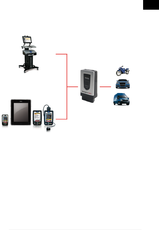
8 INTRODUCTION
NAVIGATOR NANO an advanced self-diagnostic device for cars,
motorcycles and commercial vehicles equipped with an OBD
socket.
NAVIGATOR NANO has been developed according to TEXA's
"two-unit diagnosis" approach (diagnostic device used in
combination with a display unit), in order to optimize the
practicality and versatility of portable wireless solutions.
This device is compatible with the following Texa display units
only: AXONE 4, AXONE DIRECT, AXONE PAD, AXONE
PALMTOP and MULTIPEGASO.
NAVIGATOR NANO has been designed to be connected directly
to the vehicle OBD socket; however, thanks to special cables and
adapters it can be connected to other types of sockets as well
(non-OBD cars and motorcycles).
26
9 DESCRIPTION
This chapter describes the general features of the NAVIGATOR
NANO diagnostic interface.
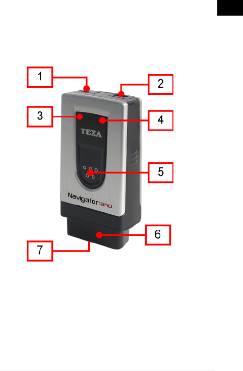
9.1 Image of the device
1. PV: a connector that may be required when the control unit that you will
be reprogramming requires auxiliary power.
2. USB connector: USB connector used to connect to the viewing unit.
3. Green LED: indicates if the tool is being powered and indicates the
status of communication with the control unit.
4. Blue LED: indicates the Bluetooth communication status.
5. LED light on button.
6. Diagnosis connector: OBD diagnosis connector.
27
en

7. LED light: LED for lighting up the work area.
9.2 Technical Features
Processor: CORTEX M3 STM32F103
72MHz
External SRAM memory: 8 MBits organized 512 KBytes x
16 bits
NAND Flash external
memory: 132 MBits on 8-bits bus
Internal battery: Lithium polymer, single cell, 3.7
V 120 mA/h
Vehicle Battery: 12 VDC Systems management
External power supply: 8 ÷ 16 V
Wireless connection: Bluetooth class1 (30 m)
Diagnostic connector: OBD
Supported protocols:
•Blink codes
•K, L, (with current protection 60
mA) ISO9141-2, ISO14230
•CAN ISO11898, ISO11519-2
•SAE J1850 PWM and VPW
•EOBD (all protocols):
SAE1979, SAEJ2534-1,
ISO15031-5, ISO15765-4
Power Supply Connector: OBD
Visual warnings: 1 green LED, 1 blue LED
28

Maximum current drawn: Normal operation: 200
mA@12V standard,
500mA@12V maximum
Operating temperature: 0 ÷ 50 °C
Stocking temperature: -20 ÷ 60 °C
Operating moisture: 10% ÷ 80% without
condensation
Dimensions: 23x45x87 mm
Weight: 62 g
Standards:
•Directive: 1999/5/CE
•Safety: EN 60950-1
•Electromagnetic compatibility:
EN 55022, EN 55024, EN 301
489-1
•Radio systems: EN 301 489-17,
EN 300 328-2
29
en

10 HOW TO USE THE DEVICE
NAVIGATOR NANO must be used by qualified personnel.
TEXA S.p.A. offers its clients professional training courses.
In these training courses the techicians are followed step by
step by specialized personnel. Their goal is to give these
technicians as much familarity with the tools and their
software as possible. This way the technicians will learn how
to make the best use of TEXA S.p.A. products.
For more information regarding training courses offered by
TEXA S.p.A. go to our website www.texa.it.
30

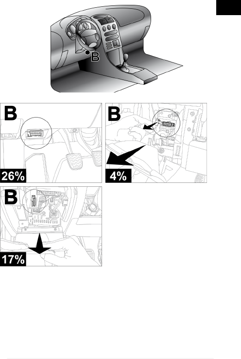
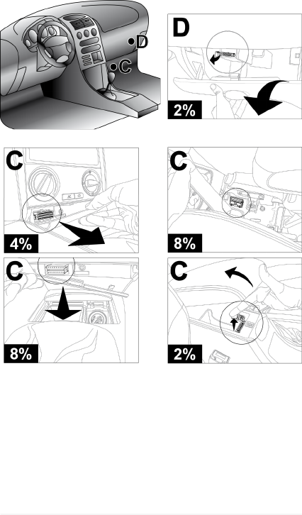
10.1 Location of the OBD Socket
The images below indicate where the diagnosis connector
may be located.
We always recommend checking the location of the OBD
socket in the vehicle user manual.
The percentages indicated in each image refer to
how often the manufacturers install the socket in that
specific area.
The OBD socket is often located near plastic or
metal elements and/or cables in general which could be
damaged if you are not careful when you install the
device.
Do not force the device or the connectors and take
the utmost care when connecting and disconnecting
them.
31
en

32
33
en
34

10.2 Powering the Device
The internal battery within the device powers the LED light
only; make sure the device is powered correctly during
diagnosis.
The device can be powered in any of the following three ways:
•via the diagnosis connector
•directly from the battery
•through lighter cable
The green LED remains on (does not flash) if the device is
being powered properly.
Do not use external batteries that are not
electrically connected to the vehicle you are working on.
10.2.1 Powering the Device via the OBD Socket
The device can be powered via the OBD socket of the vehicle
being tested.
For more information on how to connect the device
to the vehicle diagnostic socket consult the chapter
"Connecting to the Control Unit".
The green LED remains on (does not flash) if the device is
being powered properly.
35
en

10.2.2 Power Directly from Battery
Power can be drawn directly from the vehicle battery via
specific adapters and cables.
If the battery is in the rear of the vehicle, we
recommend connecting the tool directly to the power
supply points coming from the battery, available near the
area in which you are operating.
Only use the battery power when specifically
requested to do so by the software.
36
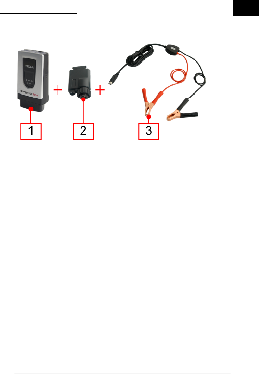
JACK CONNECTOR
The device can be powered via a suitable cable that can be
connected directly to the car adapter.
•Device
•Car adapter
•Battery clamps (with jack connector)
Proceed as follows:
1. Connect the device to the adapter.
2. Connect the clamps to the adapter.
3. Connect the clamps to the vehicle battery.
The green LED remains on (does not flash) if the device is
being powered properly.
In this case the green LED on the junction box of the clamps
will also turn on.
37
en
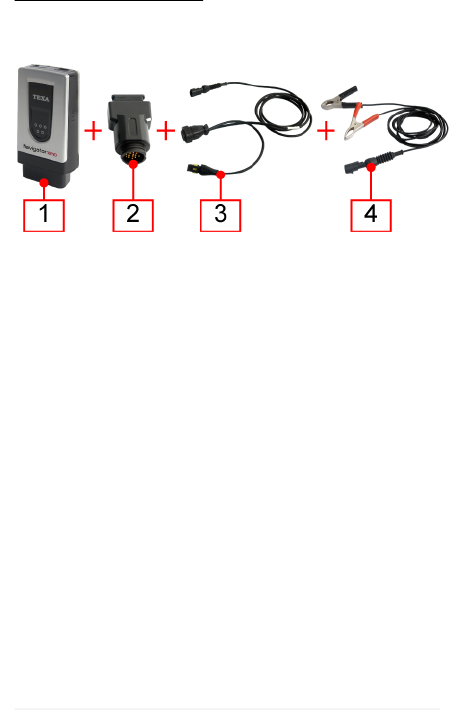
POWER SUPPLY CABLE
The tool can be powered via a power supply cable
connected to specific diagnosis cables.
1. Device
2. Motorcycle adapter
3. Diagnosis cable
4. Battery clamps (with superseal connector)
Proceed as follows:
1. Connect the device to the adapter.
2. Connect the diagnosis cable to the adapter.
3. Connect the clamps to the cable.
4. Connect the clamps to the vehicle battery.
This power supply mode can also be used on cars and
commercial vehicles using suitable adapters and diagnosis
cables.
The same connection procedure applies to all.
38
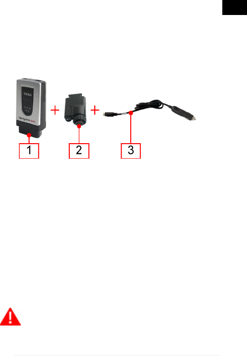
10.2.3 Power Ssupply Through Lighter Cable
The device may also be powered by the battery⌐ of the
vehicle being tested, thanks to an appropriate cable which
can be connected to the car adapter via a jack.
The connection through the lighter socket (if available) is
possible only by using an appropriate cable.
1. Device
2. Car adapter
3. Connection cable for the cigarette lighter socket
Proceed as follows:
1. Connect the device to the adapter.
2. Connect the connection cable for the cigarette lighter socket to the
adapter.
3. Connect the cable to the cigarette lighter socket.
The green LED remains on (does not flash) if the device is
being powered properly.
In this case the green LED on the connector for the lighter
socket will also turn on.
If using the cigarette lighter socket within the
vehicle make sure power is continuously being supplied
(therefore not just with the ignition key on the ON
39
en

position). Use an external battery only when indicated; in
these cases connect the negative pole of this battery to
the ground of the vehicle being diagnosed.
10.3 Recharging the Internal Battery
The device is equipped with an internal battery that powers
the LED light only.
To charge the internal battery simply power the device using
the vehicle battery or connect the display unit via USB.
We suggest powering the display unit using the mains when
charging the device via USB.
40

10.4 How to Communicate with the Viewing Unit
The tool is not equipped with a user interface and the data
acquired is sent to an appropriate viewing unit.
Before starting the communication with the display
unit, you must perform the special configuration
procedure.
The connection of the tool to the display unit can occurr in the
following modes:
•Bluetooth
•USB
To best exploit the potential of the tool, you must use the
Bluetooth connection.
Power, connect and turn on the tool before starting
up the programs which will be used to interface with it. If
this procedure is not followed communication errors
could occur.
While the tool is turning on it automatically detects the
communication mode through which it is connected to the
display unit.
For example: the Bluetooth communication mode (active by
default) is disabled when the USB cable is connected.
To change the communication mode between the
tool and the viewing unit you must first turn off the tool
and then choose the mode you prefer.
41
en
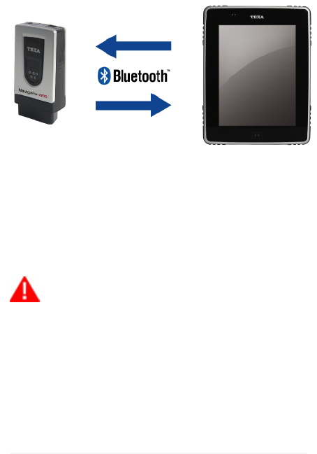
10.4.1 Connecting via Bluetooth
The wireless connection eliminates the communication cable
with the display unit, making the tool more practical to use.
The serial number to use in order to configure Bluetooth
communication can be found on the label behind the OBD
connector.
The blue LED flashes:
•During the configuration phase of the Bluetooth communication.
•During communication between the tool and the viewing unit,
during data transmission.
For a correct configuration we recommend
powering the tool (making sure the green LED is on)
before launching the configuration procedure of the
software.
For more information regarding the configuration
procedure consult the Software Operating Manual.
42

10.4.2 Connection via USB
In order to connect via USB use the USB cable provided or,
if necessary, use cables on which "USB HIGH SPEED is
specifically indicated.
This powering mode is recommended during control unit
reprogramming operations.
1. Device
2. USB cable
3. Display unit
Proceed as follows:
1. Connect the USB mini connector of the USB cable to the device.
2. Connect the USB connector of the USB cable to the display unit.
3. Continue with the communication software configuration.
The internal battery of the device will be charged when the
display unit is connected via USB.
For more information regarding the configuration
procedure consult the Software Operating Manual.
43
en

10.5 Blink Code
The LEDs on the devices flash to indicate the various states
of the devices themselves, both while they are connecting to
the display unit and when they are connecting to the vehicle.
LED STATUS
GREEN
OFF Device not powered.
ON Device powered.
Blinking Tool in communication with the vehicle
control unit.
BLUE
Off No Bluetooth communication.
ON --
Blinking Device in communication with the
display unit.
44
10.6 Connecting to the Control unit
To carry out self-diagnosis you are required to connect the
tool to the diagnosis socket of the vehicle and activate the
connection between the tool and control unit via the software.
Proceed as follows:
1. Via the software select the vehicle and the system on which you
wish to carry out the self-diagnosis.
2. Locate the diagnostic socket using the information (images or
short video) provided by the software.
3. Connect the tool to the control unit using, when required, the
appropriate cables and adapters indicated by the software. .
A flashing green LED indicates that the vehicle control unit
and the device are communicating correctly.
The position and the type of the socket on the vehicles vary
according to the make and model; this is why the software
provides the information required to locate it.
45
en

Carefully follow the instructions provided by the
software.
If not otherwise specified, supply the tool directly
by the connection with the diagnostic socket of the
vehicle.
For further information see the operating manual of the
software.
10.6.1 LED Light
The LED light allows you to light up the diagnosis connector
and the work area.
Proceed as follows:
Press and hold the on button.
The LED light turns on.
Release the button to turn off the LED light.
46

10.7 Pass-Thru
Thanks to NAVIGATOR NANO and a simple Internet access
you can carry out all the repairs that require the original
reprogramming of the vehicle control units once they have
been replaced.
In compliance with protocol SAE J2534 Pass-Thru, vehicle
manufacturers must offer independent repair shops the
possibility to carry out reprogramming on vehicle control
units.
You need an active and working Internet connection.
(ADSL is strongly recommended).
The type of Internet connection required may vary
depending on the manufacturer's specific requirements.
47
en

When using Pass-Thru, auxiliary power may be
required in order to recharge the vehicle battery.
The activation date, the actual availability, the
type, the cost and the procedures regarding the use of
the Pass-Thru service(s) are specifically determined by
the individual manufacturer; costs, performance, and
procedures may therefore vary independently from what
TEXA S.p.A establishes.
TEXA S.p.A. is not under any circumstance liable
for repair and maintenance work carried out on vehicles;
by using the technical information and/or the service(s)
offered by the specific websites of individual
manufacturers, in this sense, Pass-Thru procedures are
subject to the acceptance of specific liability regulations
defined by the individual vehicle manufacturer.
48

10.8 Self-diagnosis
The data acquired by the tool are displayed on the viewing
unit via the software.
The software provides functions that allow you, for instance,
to do the following:
•monitor the engineering parameters
•view and delete the errors detected by the control unit
•check the various states within the control unit (ex.: engine running/
not running, low beams on/off)
•view the information related to the control unit
•test the operation of the devices driven by the control unit
(actuators)
•carry out permanent adjustments on certain devices
Furthermore, the software provides technical sheets useful in
diagnosis and provides step by step procedures to carry out
particular operations (ex.: resetting warning lights).
All the configuration operations of the tool are performed via
the software.
For more information about the installation of the
software and its use, please refer to the Setup Manual
and the Operation Manual.
49
en

11 MAINTENANCE
The tool does not require special maintenance.
For a longer life of the tool, keep it clean and follow the
instructions provided in this manual carefully.
If necessary, contact your Dealer or the Technical
Assistance Service.
50

12 SOLUTIONS TO PROBLEMS
For any technical problem contact your retailer/distributor.
Below you will find a list of simple instructions that the client
can carry out without having to ask for technical assistance.
PROBLEM PROBABLE
CAUSE POSSIBLE
SOLUTION
The device is not
communicating with
the control unit.
The tool /
diagnostic cable is
not connected
properly.
Connect the
tool / diagnostic
cable properly.
The adapter being
used is not
suitable.
Use a suitable
adapter.
The diagnostic
cable is damaged. Change the
diagnostic cable.
The diagnosis
connector is
damaged.
Contact
Technical
Assistance.
The vehicle is off. Turn on the
vehicle.
The tool cannot
communicate with
the display unit/
Bluetooth
peripherals.
The Bluetooth
peripheral/display
unit is turned off.
Turn on the
Bluetooth
peripheral/
display unit.
51
en

PROBLEM PROBABLE
CAUSE POSSIBLE
SOLUTION
The tool cannot
communicate
with the display
unit/ Bluetooth
peripherals.
The Bluetooth
peripheral/display
unit is not within the
tool's range.
Move the
Bluetooth
peripheral/display
unit into the tool's
range.
Move the tool into
the range of the
Bluetooth
peripheral/display
unit.
The device has not
been properly
configured.
Perform the
configuration
through the special
function in the
software.
The tool has been
placed near
shielding materials.
Place the tool
away from
shielding
materials.
The presence of
other wireless
communications
disturbs the signal.
Move away from
possible sources
of interference.
If possible, turn off
the devices that
cause
interference.
Wait and repeat
the communication
attempt.
52

13 LEGAL NOTICES
For information regarding the legal notices, please refer to
International Warranty Booklet provided with the product in
your possession.
53
en