Texa S p A TTC11 Veichle belt tension analyzer User Manual MU DBA en GB DEX02kk
Texa S.p.A. Veichle belt tension analyzer MU DBA en GB DEX02kk
User Manual

ENGLISH...............................................................5
en

2

SUMMARY
Introduction........................................................................................5
1 LEGEND OF THE SYMBOLS USED...........................................6
2 GENERAL SAFETY REGULATIONS..........................................7
2.1 Glossary..........................................................................................7
2.2 Operator Safety Regulations...........................................................7
2.2.1 General Safety Regulations................................................................7
2.2.2 Risk of Asphyxiation............................................................................7
2.2.3 Risk of Impact and Crushing...............................................................8
2.2.4 Hazards Caused by Moving Parts......................................................8
2.2.5 Risk of Burning or Scalding................................................................8
2.2.6 Fire and Explosion Hazard.................................................................9
2.2.7 Noise Hazard......................................................................................9
2.2.8 High Voltage Hazard...........................................................................9
2.2.9 Poisoning Hazard.............................................................................10
2.3 General User and Maintenance Warnings....................................11
3 SPECIFIC SAFETY RULES FOR USING DUCATI BELT
ANALYZER.....................................................................................12
3.1 Glossary........................................................................................12
3.2 General Rules...............................................................................12
3.3 Operator Safety.............................................................................12
3.4 Tool Safety....................................................................................13
4 ENVIRONMENTAL INFORMATION..........................................15
5 NORMATIVE INFORMATION....................................................16
6 DESCRIPTION OF DUCATI BELT ANALYZER........................17
6.1 Image of the Tool..........................................................................18
6.1.1 Display..............................................................................................19
6.2 Technical Features........................................................................19
7 TOOL OPERATION...................................................................20
7.1 Power Supply................................................................................20
3
en

7.1.1 Charge..............................................................................................20
7.2 Power on.......................................................................................21
7.3 Measurement................................................................................22
7.3.1 Work Zone lighting............................................................................25
7.4 Power off.......................................................................................26
8 MAINTENANCE.........................................................................27
9 SOLUTIONS TO PROBLEMS....................................................28
10 LEGAL NOTICES.....................................................................30
4

TECHNICAL MANUAL OF DUCATI BELT ANALYZER
Introduction
Dear Customer,
We would like to thank you for choosing a TEXA product for your workshop.
We are certain that you will get the greatest satisfaction from it and receive
a great deal of help in your work.
Please read through the instructions in this manual carefully and keep it for
future reference.
Reading and understanding the following manual will help you to avoid
damage or personal injury caused by improper use of the product to which
it refers.
TEXA S.p.A reserves the right to make any changes deemed necessary
to improve the manual for any technical or marketing requirement; the
company may do so at any time without prior notice.
This product is intended for use by technicians specialized in the
automotive field only. Reading and understanding the information in this
manual cannot replace adequate specialized training in this field.
The sole purpose of the manual is to illustrate the operation of the product
sold. It is not intended to offer technical training of any kind and technicians
will therefore carry out any interventions under their own responsibility and
will be accountable for any damage or personal injury caused by
negligence, carelessness, or inexperience, regardless of the fact that a
TEXA S.p.A. tool has been used based on the information within this
manual.
Any additions to this manual, useful in describing the new versions of the
program and new functions associated to it, may be sent to you through
our TEXA technical bulletin service.
This manual should be considered an integral part of the product to which
it refers. In the case it is resold the original buyer is therefore required to
forward the manual to the new owner.
Reproduction, whole or in part, of this manual in any form whatsoever
without written authorization from the producer is strictly forbidden.
© copyright and database rights 2010. The material contained in this
document is protected by copyright and database rights. All rights reserved
according to law and international agreements.
5
en

1 LEGEND OF THE SYMBOLS USED
The symbols used in the manual are described in this chapter.
Asphyxiation Risk
Explosion Risk
High Voltage Hazard
Fire / Burn risk
Poisoning Hazard
Corrosive Substances Risk
Noise Hazard
Moving Parts Risk
Crushing Risk
General Risk
Important information
6

2 GENERAL SAFETY REGULATIONS
2.1 Glossary
•Operator: qualified individual, in charge of using the device/tool.
•Machine/device/tool: the product purchased.
•Workplace: the place where the operator must carry out her/his work.
2.2 Operator Safety Regulations
2.2.1 General Safety Regulations
•The operator must be completely clear-headed and sober when using the
device; taking drugs or alcohol before or when operating the device is strictly
forbidden.
•The operator must not smoke during device operation.
•The operator must carefully read all the information and instructions in the
technical documents provided with the device.
•The operator must follow all the instructions provided in the technical
documents.
•The operator must always watch over the device during the various operating
phases.
•The operator must make sure she/he is working in environment which is
suitable for the operations that must be carried out.
•The operator must report any faults or potentially hazardous situation in
connection with the workplace or the device.
•The operator must carefully follow the safety regulations required for the
workplace in which she/he is working and required by the operations she/he
has been asked to carry out.
2.2.2 Risk of Asphyxiation
Exhaust gas from internal combustion engines, whether they may
be petrol or diesel, are hazardous to your health and can cause
serious harm to your body.
Safety Precautions:
•The workplace must be equipped with an adeguate ventilation and air
extraction system and must be in compliance with standards according to
current national laws.
•Always activate the air extraction system when working in closed
environments.
7
en
2.2.3 Risk of Impact and Crushing
The vehicles which are undergoing A/C system recharging
operations and the devices, must be properly blocked using the
specific mechanical brakes/blocks, while being service.
Safety Precautions:
•Always make sure that the vehicle is in neutral gear (or that it is set in parking
position in case of a vehicle equipped with automatic transmission).
•Always activate the hand brake or parking brake on the vehicle.
•Always block the wheels on the vehicle with the specific mechanical blocks.
•Make sure the device is stable, on a flat surface and the wheels are locked
with the specific brakes.
2.2.4 Hazards Caused by Moving Parts
Vehicle engines include parts that move, both while running and
not running (eg: the cooling fan is controlled by a thermal switch
in connection with the coolant temperature and become activated
even when the vehicle is off), that can injure the operator.
Safety Precautions:
•Keep hands away from moving parts.
•Disconnect the engine cooling fan each time the engine you are working on
is still hot. This will avoid the fan from becoming activated unexpectedly even
when the engine is off.
•Do not wear ties, loose clothes, wrist jewellery or watches when working on
a vehicle.
•Keep connection cables, probes and similar devices away from the moving
parts of the engine.
2.2.5 Risk of Burning or Scalding
The parts that are exposed to high temperatures in engines that
are moving or have just stopped could burn the operator.
Remember that catalytic mufflers reach very high temperatures,
able to cause serious burns or even start fires.
Acid in the vehicle batteries is another potential hazard.
Safety Precautions:
•Protect your face, hands, and feet by using suitable protection.
•Avoid contact with hot surfaces, such as spark plugs, exhaust pipes,
radiators and connections within the cooling system.
8
•Make sure there are no oil stains, rags, paper or other inflammable material
near the muffler.
•Avoid splashing electrolyte on skin, eyes and clothes, as it is a corrosive and
highly toxic compound.
2.2.6 Fire and Explosion Hazard
The following are potential fires and/or explosion hazards:
•The fuel used by the vehicle and the fumes from the fuel may cause
fires or explosions.
•The refrigerants used by the A/C system can cause fires.
•The acid in the vehicle batteries.
Safety Precautions:
•Let the engine cool.
•Do NOT smoke near the vehicle.
•Do NOT expose the vehicle to open flames.
•Make sure that the electrical connections are all well insulated and firmly in
place.
•Collect any fuel that might have spilled.
•Collect any refrigerant that might have spilled.
•Make sure you are always working in an environment equipped with a good
ventilation and air extraction system.
•Always activate the air extraction system when working in closed
environments.
•Cover the openings of the batteries with a wet cloth in order to stifle the
explosive gases before proceeding in testing or recharging.
•Avoid causing sparks when connecting cables to the battery.
2.2.7 Noise Hazard
Loud noises that may occur within the workplace, especially during
service operations may damage the operator's hearing.
Safety Precautions:
•Protect your ears with suitable protective ear wear.
2.2.8 High Voltage Hazard
The voltage supply from the mains that powers the devices in the
workplace and the voltage within the vehicle starter system is a
potential shock hazard to the operator.
9
en
Safety Precautions:
•Make sure the electrical system in the workplace is compliant to current
national standards.
•Make sure the device being used is connected to ground.
•Cut off the power supply voltage before connecting or disconnecting cables.
•Do NOT touch the high voltage cables when the engine is on.
•Operate in conditions of insulation from ground.
•Work with dry hands only.
•Keep conductive liquids away from the engine while working.
•Never leave tools on the battery in order to avoid accidental contacts.
2.2.9 Poisoning Hazard
The hoses used to extract the refrigerants can release toxic gases,
dangerous to the operator if exposed to temperatures higher than
250 °C or in case of a fire.
Safety Precautions:
•Contact a doctor immediately should you inhale these gases.
•Use neoprene or PVC gloves when eliminating combustion deposits.
10

2.3 General User and Maintenance Warnings
•When using the device or carrying out scheduled maintenance (eg. fuse
replacement) on the device, carefully follow the information provided below.
•Do not remove or damage the labels/tags and the warnings on the device;
do NOT in any case make them illegible.
•Do not remove, or block, any safety devices the device is equipped with.
•Only use original spare parts or spare parts approved by the manufacturer.
•Contact your retailer for any non-scheduled maintenance.
•Periodically check the electrical connections of the device, making sure they
are in good condition and replacing any damaged cables.
•Check parts that are subject to wear periodically and replace if necessary.
•Do not open or disassemble the device.
11
en

3 SPECIFIC SAFETY RULES FOR USING DUCATI
BELT ANALYZER
The technology used for the design and control of the manufacturing of
Ducati Belt Analyzer makes it a reliable, simple and safe device to use.
Personnel in charge of using the diagnostic tools is required to follow the
general safety rules, use the Ducati Belt Analyzer device for its intended
use and keep it correctly, as described in this manual.
3.1 Glossary
Operator: qualified person responsible for using the diagnosis tool.
Tool/device: any Ducati Belt Analyzer device.
3.2 General Rules
•The operator must have basic knowledge in mechanics, automotive, car
repairs and potential dangers that can occur during the auto-diagnosis
operations.
•The operator must carefully read all the information and instructions in the
technical documents provided with the tool.
3.3 Operator Safety
The resonance frequency measurement of a belt requires to
operate very close to the engine.
Safety Measures:
•Check that the engine is switched off and cold.
•Check that the belt to be examined is not in motion.
•Check that the belt is not likely to get moving during operations.
12
3.4 Tool Safety
The tool was designed for the use in specific environmental
conditions.
The use of the tool in environments with temperature and moisture
characteristics different from those specified may impair its
efficiency.
Safety Measures:
•Place the tool in a dry place.
•Don not expose or use the tool near heat sources.
•Position the tool making sure it can be properly ventilated.
•Do not use corrosive chemicals, solvents or harsh detergents to clean the
tool.
The tool was designed so as to be mechanically tough and suitable
for use in a workshop.
Carelessness in the use and excessive mechanical stresses may
impair its efficiency.
Safety Measures:
•Do not drop, shake or subject the tool to shocks.
•Do not perform any kind of intervention that may damage the tool.
•Do not open or dismantle the tool.
The tool was designed so as to be electrically safe and to work
with specific power supply voltage levels.
Failure to comply with the specifications related to the power
supply may impair the tool efficiency.
Safety Measures:
•Do not wet with water or other liquids.
•The power supply of the tool must be always connected according to the
procedures shown in the present manual.
•Never use external batteries to power the tool.
•While recharging from mains use only the battery charger that might be
supplied with the kit.
13
en

Electromagnetic compatibility tests on the tool ensure that it can
be adapted to technologies normally used on vehicles (e.g.:
engine check, ABS, etc.). Nevertheless, if malfunctions occur you
need to contact the retailer.
14

4 ENVIRONMENTAL INFORMATION
For information regarding the disposal of this product please
refer to the pamphlet accompanying your tool.
15
en

5 NORMATIVE INFORMATION
Compliance declaration
TEXA S.p.A hereby declares that the Ducati Belt Analyzer unit
complies with the essential requirements and provisions of the
Directive 2004/108/EC.
A complete copy of the Declaration of Conformity can be obtained at
TEXA S.p.A., Via 1 Maggio 9, 31050 Monastier di Treviso (TV), Italy
FCC Compliance
This device complies with Part 15 of the FCC Rules.
Operation is subject to the following two conditions: (1) this device may not
cause harmful interference, and (2) this device must accept any
interference received, including interference that may cause undesired
operation.
Change or modifications not expressly approved by the party responsible
for compliance could void the user’s authority to operate the equipment.
This equipment has been tested and found to comply with the limits for a
Class B digital device, pursuant to part 15 of the FCC Rules. These limits
are designed to provide reasonable protection against harmful interference
in a residential installation. This equipment generates, uses and can
radiate radio frequency energy and, if not installed and used in accordance
with the instructions, may cause harmful interference to radio
communications. However, there is no guarantee that interference will not
occur in a particular installation. If this equipment does cause harmful
interference to radio or television reception, which can be determined by
turning the equipment off and on, the user is encouraged to try to correct
the interference by one or more of the following measures:
- Reorient or relocate the receiving antenna.
- Increase the separation between the equipment and receiver.
- Connect the equipment into an outlet on a circuit different from that to
which the receiver is connected.
- Consult the dealer or an experienced radio/TV technician for help.
16
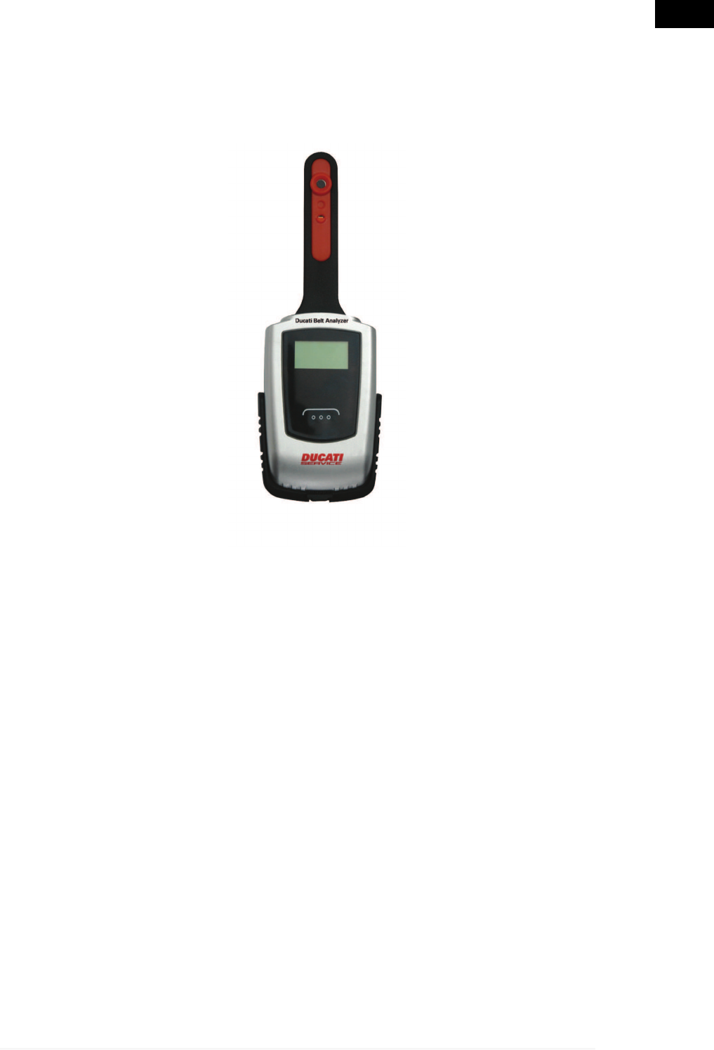
6 DESCRIPTION OF DUCATI BELT ANALYZER
Ducati Belt Analyzer (DBA) is a precision tool for the measurement of the
oscillation frequency of the engine belts.
By means of special tables it is possible to derive the belt tension starting
from the measured oscillation frequency.
The small dimensions and the ease in the use make DBA a practical and
reliable tool, suitable for the needs of every body shop.
17
en
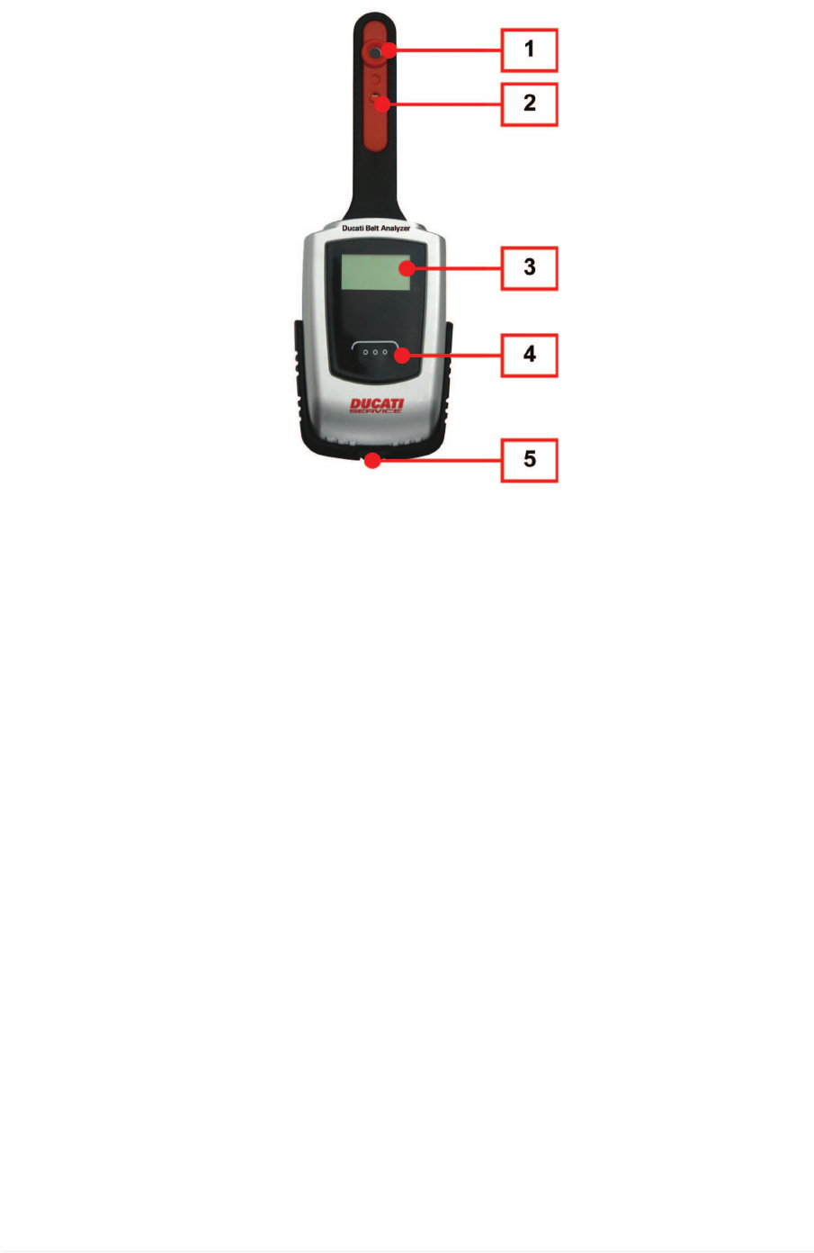
6.1 Image of the Tool
1. Microphone
2. LED
3. Backlit display
4. ON/OFF button
5. USB Port *
(*) Only for internal battery recharge.
18
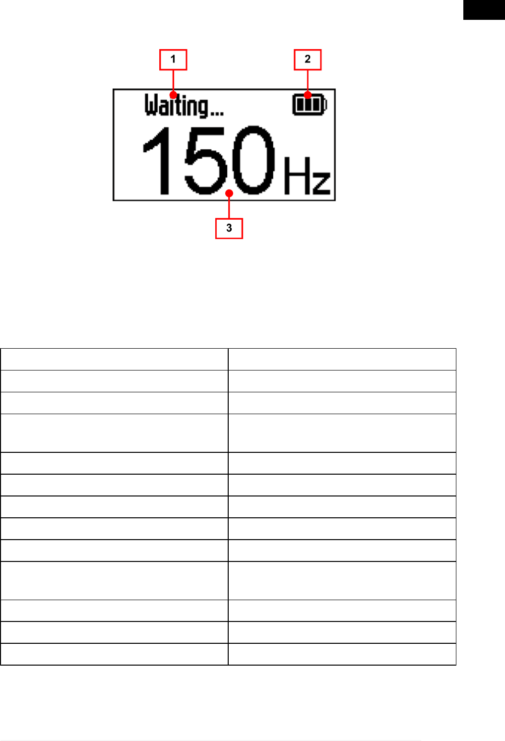
6.1.1 Display
1. Action: shows the operation and the present status of the device
2. Battery: shows the battery status (see chapter Power Supply)
3. Frequency: shows the measured oscillation frequency.
6.2 Technical Features
Micro controller: ARM 32 bit
Display: Backlit LCD
Internal battery: 3.7 V 1000 ma/h li-io
Recharge: from USB port, max consumption
470 mA
Range: 6 hours of continuous operation
Resolution: 3 Hz
Accuracy: ± 1,5 Hz
Operating temperature: - 10 °C ÷ 40 °C
Stocking temperature: - 20 °C ÷ 60 °C
Temperature with battery under
charge: 0 °C ÷ 45 °C
Storage and operation moisture: 10% ÷ 80% without condensation
Dimensions: 202,7 x 70,6 x 31,3 mm
Weight: 0,3 kg
19
en
7 TOOL OPERATION
DBA must be used by qualified personnel.
7.1 Power Supply
The tool is powered with an internal battery.
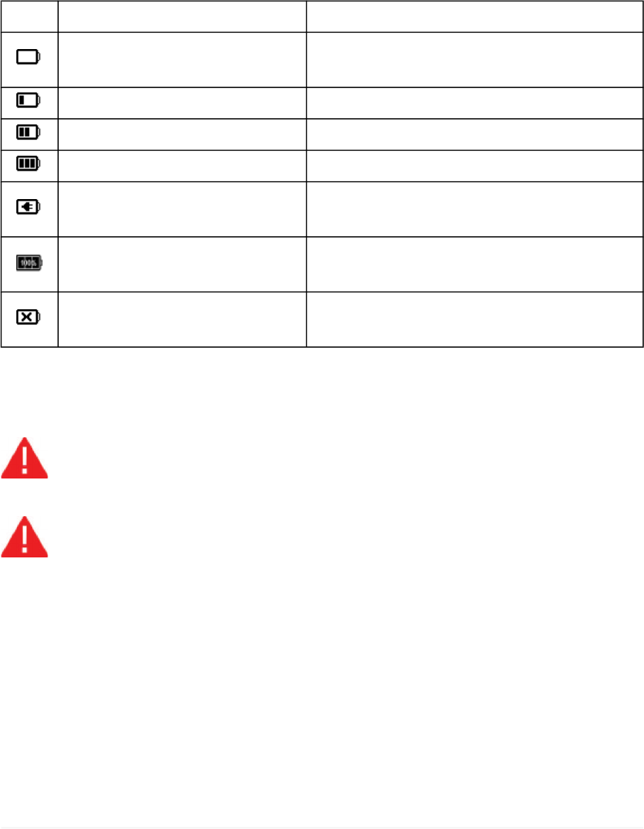
The battery charge status is shown by a special icon.
ICON WHEN IT APPEARS MEANING
During use Battery charge lower than 26%.
Recharge as soon as possible.
During use Charge level between 26% and 50%.
During use Charge level between 50% and 75%.
During use Charge level between 75% and 100%.
With tool switched on or off,
during recharge Battery in charge.
With tool switched off,
during recharge Charge complete.
With tool switched on or off,
during recharge Internal battery charger not working.
7.1.1 Charge
The internal battery can be recharged by connecting the tool to a PC.
Do not charge the tool in environments with temperature lower
than 0 °C or higher than 45 °C.
Do not use the tool while recharging.
Proceed as follows:
1. Turn on the PC.
2. Connect the USB cable to the tool.
3. Connect the USB cable to the PC.
The completely dead battery takes about 4 hours to fully recharge.
20
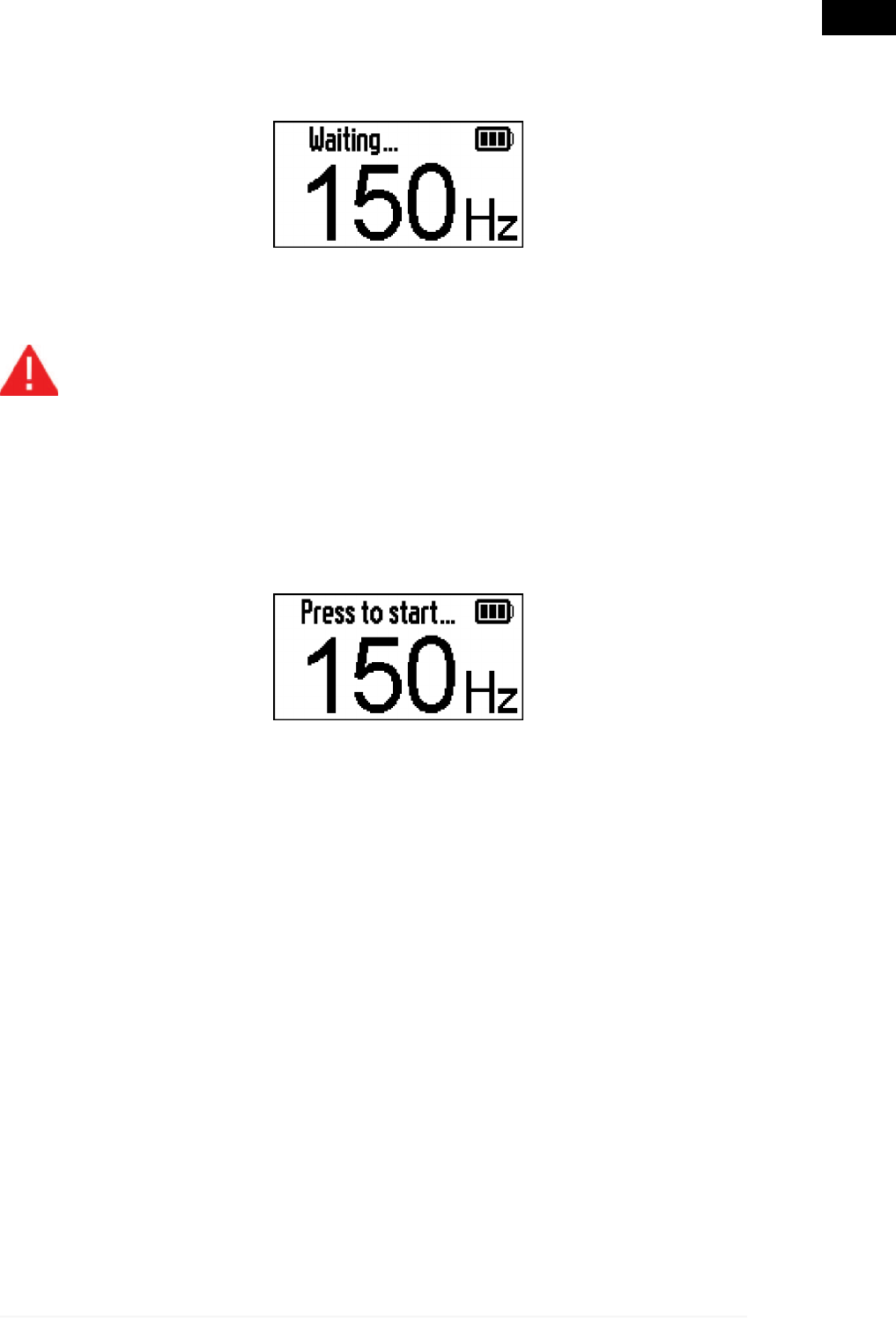
7.2 Power on
To turn on the tool proceed as follows:
Hold down the power button for about 2 seconds until the tool beeps and
the LED flashes.
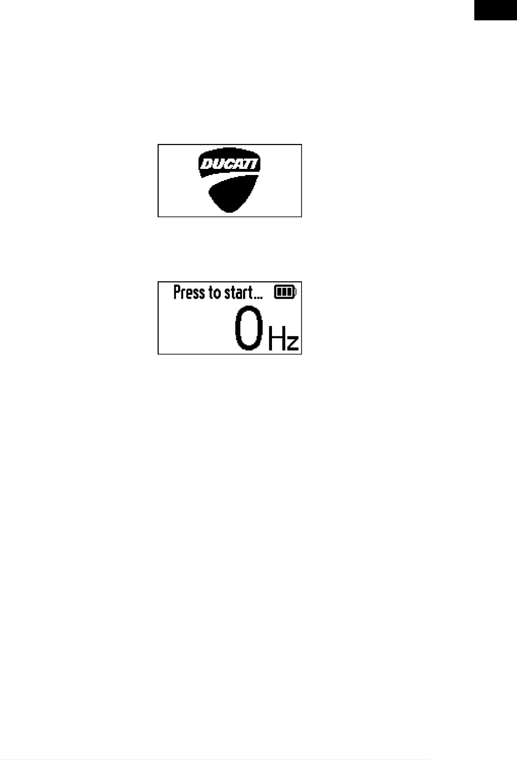
When you switch on the initial screen with the logo appears.
The flashing message "Press to start ..." shows that the tool is ready for
use.
21
en
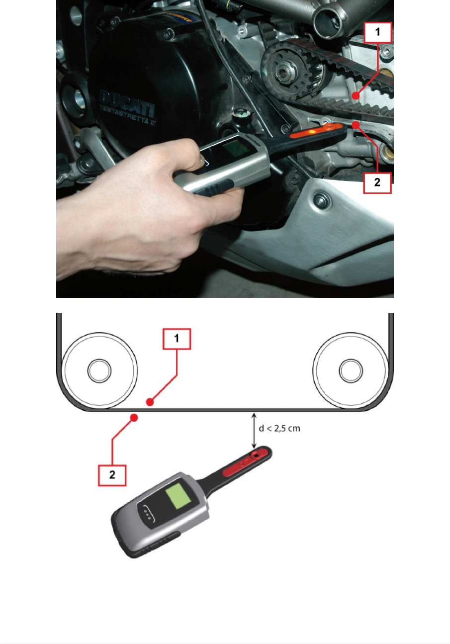
7.3 Measurement
The measurement can be equally done either from the internal side or the
external side of the belt (see picture and figure).
1. Internal side
2. External side
22
The microphone must be placed at a distance from the belt not higher
than 2.5 cm.
The point where to place the tool and the conversion tables for oscillation
frequency - tension are supplied by Ducati Service.
Minimize the background noise of the environment, to optimize
the tool performances.
Do not place the microphone on the belt.
Do not cover the microphone.
Proceed as follows:
1. Turn on the tool.
2. Place the tool with microphone pointing to the belt.
3. Hold down and release the power button.
The LED lights on and the tool begins to search for the oscillation frequency
of the belt.
The LED remains on for about 10 seconds, within which the tool can
make multiple measurements, each linked to a stress of the belt.
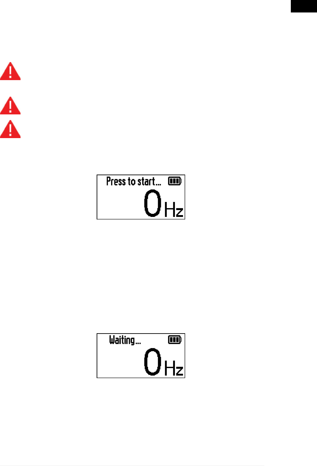
4. Check that there is no noise and that the frequency read on the tool is 0
Hz.
23
en
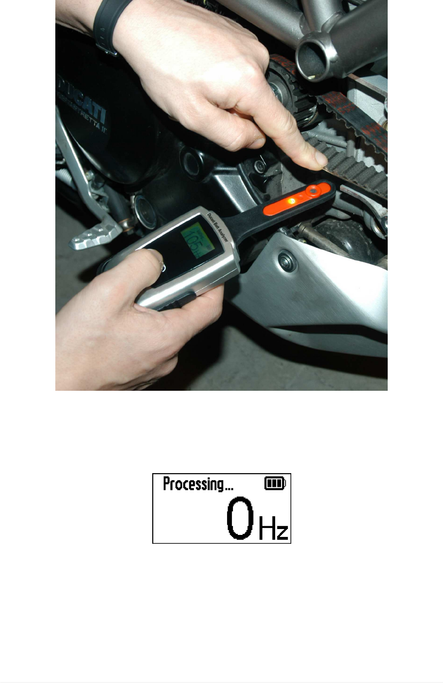
5. Stress the belt with a finger to cause its vibration.
The tool registers the oscillation frequency of the belt and processes data.
The process status is highlighted by the flashing message "Processing...
".
24
At the end of each processing the tool beeps, the LED flashes and the
resonance frequency of the belt is shown.
6. Repeat the measurement 3 times and calculate the average of the read
values.
The values to be used for the calculation of the average must
have a difference not higher than 3 Hz.
7. Use the calculated value to derive with the special tables the tension of
the belt.
At the end of the 10 seconds the tool comes back to the status "Press to
start ...".
7.3.1 Work Zone lighting
The LED near the microphone enables to light the belt stretch and the work
zone.
Proceed as follows:
Press and release the power button.
The led lights on.
The LED will turn off automatically after about 10 s.
25
en

7.4 Power off
The tool switching-off can happen in two ways:
•automatic
•manual
AUTOMATIC OFF
The tool has a function of automatic switching-off which activates after 3
minutes of inactivity.
The tool emits a long beep and the LED flashes.
The screen showing automatic switching-off appears.
The tool switches off.
MANUAL OFF
It is possible to switch off the tool at any time.
Proceed as follows:
Hold down the power button until the tool beeps.
The tool switches off.
26

8 MAINTENANCE
The tool does not require special maintenance.
For a longer life of the tool, keep it clean and follow the instructions provided
in the following manual carefully.
If necessary, contact your Dealer or the Technical Assistance Service.
27
en

9 SOLUTIONS TO PROBLEMS
For any technical problem non-solvable following the instructions below,
please contact your Distributor/Dealer.
PROBLEM PROBABLE CAUSE POSSIBLE SOLUTION
With the tool connected
to PC, the indication of
battery in charge does
not pop up.
The PC is not switched
on or is in stand-by. Turn on the PC.
The USB cable is not
connected properly or is
defective.
Check connection and/
or replace the cable.
The measurement is
clearly wrong.
The distance between
microphone and belt is
excessive.
Point the microphone
towards the belt while
keeping it at the
prescribed distance.
The point of the belt
where the measurement
is done does not
correspond to the one
indicated by the
manufacturer.
Place the microphone in
the point indicated by
the vehicle
manufacturer, while
keeping it at the
prescribed distance.
The environments
where the measurement
is done is too noisy.
Minimize the
background noise of the
environment as much as
possible.
The tool is damaged,
possible damages to the
microphone.
Contact the Distributor/
Dealer.
The tool is switched on
and charged, but does
not measure.
The microphone is not
pointed towards the belt.
Point the microphone
towards the belt while
keeping it at the
prescribed distance.
28

PROBLEM PROBABLE CAUSE POSSIBLE SOLUTION
The tool is switched on
and charged, but does
not measure.
The microphone is
covered by dirt or
hindered by some kind
of material.
Gently clean the
microphone, removing
foreign bodies hindering
reception.
Be careful and do not
damage the
microphone.
29
en

10 LEGAL NOTICES
For information regarding the legal notices, please refer to International
Warranty Booklet provided with the product in your possession.
30