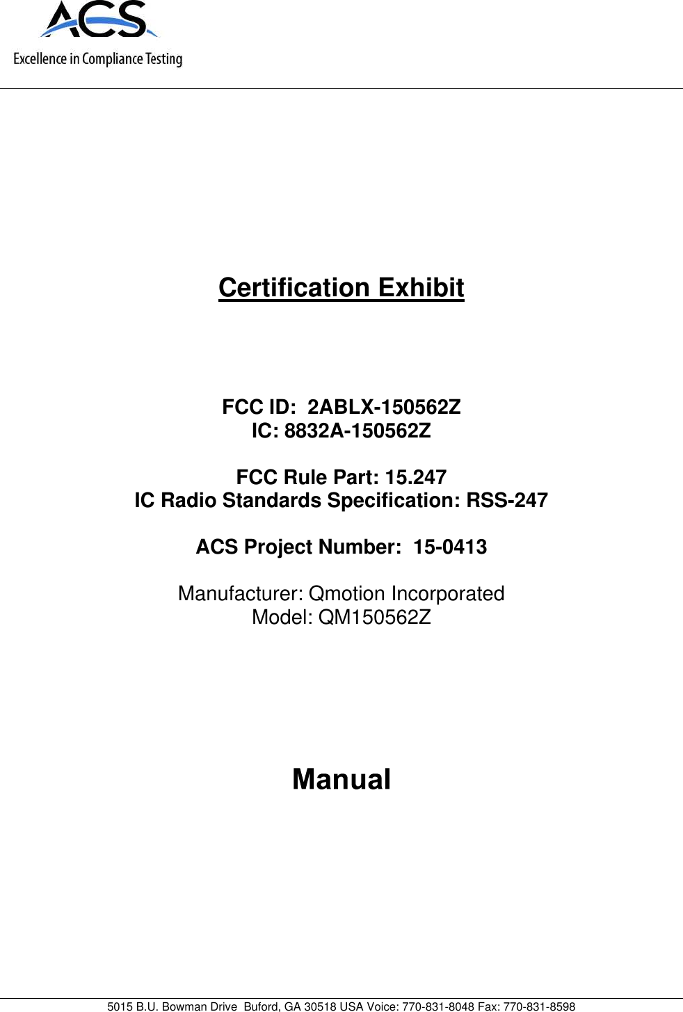
The Watt Stopper d b a Qmotion 150562Z Zigbee Hardwired Dual Channel Switch User Manual 15 0413 Exhibit Cover

Qmotion Incorporated Zigbee Hardwired Dual Channel Switch 15 0413 Exhibit Cover

Manual

5015 B.U. Bowman Drive Buford, GA 30518 USA Voice: 770-831-8048 Fax: 770-831-8598Certification ExhibitFCC ID: 2ABLX-150562ZIC: 8832A-150562ZFCC Rule Part: 15.247IC Radio Standards Specification: RSS-247ACS Project Number: 15-0413Manufacturer: Qmotion IncorporatedModel: QM150562Z
8 REVISION 1.1 07DEC15 REVISION 1.1 07DEC15 Part # Part #    QMotion ZigBee Hard Wired Control  Roller Shade Application Guide FCC  Warning: Changes or modifications to this device not expressly approved by QMotion® Incorporated -Advanced Shading Systems could void the user’s authority to operate the equipment.   NOTE: This equipment has been tested and found to comply with the limits for a Class B digital device, pursuant to Part 15 of the FCC Rules. These limits are designed to provide reasonable protection against harmful interference in a residential installation. This equipment generates, uses, and can radiate radio frequency energy and, if not in-stalled and used in accordance with the instructions, may cause harmful interference to radio communications. How-ever, there is no guarantee that interference will not occur in a particular installation. If this equipment does cause harmful interference to radio or television reception, which can be determined by turning the equipment off and on, the user is encouraged to try to correct the interference by one or more of the following measures: • Reorient or relocate the receiving antenna. • Increase the separation between the equipment and receiver. • Connect the equipment into an outlet on a circuit different from that to which the receiver is connected.   Consult the dealer or an experienced radio/TV technician for help.  This device complies with Part 15 of the FCC Rules. Operation is subject to the following two conditions:  (1)This device may not cause harmful interference, and (2) This device must accept any interference received, including interference that may cause undesired operation.  RF Exposure  This equipment complies with FCC radiation exposure limits set forth for an uncontrolled environment. This equip-ment should be installed and operated with minimum distance 20cm between the radiator and your body. This trans-mitter must not be co-located or operating in conjunction with any other antenna or transmitter.    INDUSTRY CANADA This device complies with Industry Canada licence-exempt RSS standard(s). Operation is subject to the following two conditions: (1) this device may not cause interference, and (2) this device must accept any interference, includ-ing interference that may cause undesired operation of the device.  Le présent appareil est conforme aux CNR d'Industrie Canada applicables aux appareils radio exempts de licence. L'exploitation est autorisée aux deux conditions suivantes: (1) l'appareil ne doit pas produire de brouillage, et (2) l'uti-lisateur de l'appareil doit accepter tout brouillage radioélectrique subi, même si le brouillage est susceptible d'en compromettre le fonctionnement.  RF Exposure Cet équipement est conforme aux limites ďexposition aux radiations dans un environnement noncontrôlé. Cet équipement doit être installé et utilisé à distance minimum de 20cm entre le radiateur et votre corps. Cet émetteur ne doit pas être co-localisées ou opérant en conjunction avec tout autre antenne ou transmetteur.
2  7  REVISION 1.1 07DEC15 REVISION 1.1 07DEC15 ZigBee Hardwired  Roller  Shade System Overview Power Supply: 24 VDC, 7.5A RJ-45 Ports for Motorized Shades and Switches  -  Quanty 8 Communicaon Ports (RJ-45)  - Quanty 2 Part # Part # ZigBee Hardwired  Roller  Shade Third Party Integration Wire Specification:   Category 5e/Category 6 for use with RJ-45 Connector   24 AWG   Maximum length of wire from Power Distribution Panel to device :   - 8’ X 8’ Shade with 40:1 motor  -           1250’   - 12’ X 12’ Shade with 73:1 motor  -         750’   - 12’ X 20’ Shade with 73:1 motor  -         500’   - Hardwired 4 and 8 Button Switches   - 1000’    *Length based on 115K baud rate   Maximum wire length for RS485 communication  - 2000’ Power Distribution Panel:   8  RJ-45 ports for motorized shades and switches   2 additional RJ-45 communication ports dedicated to daisy chain with other Power Distribution Panels and Third Party Integration via RS485.   Power Supply   - AC Input: 100-240 VAC, 2.5A   - DC Output: 24 VDC, 7.5A Note:   Standard Roll Applications (Motor Left) - Wire will need to be run to the LEFT side of the window (as shown).   Reverse Roll Applications (Motor Right) - Wire will need to be run to the RIGHT side of the window . Power    Distribution Panels 24 VDC Power Supplies RS485 Communication Third Party Integration System Capacity:   200 Devices (QMotion Shades, QMotion Wireless Remotes, QMotion Hardwired Switches and other ZigBee devices) *Specicaons are subject to change without noce
6   3 REVISION 1.1 07DEC15 REVISION 1.1 07DEC15 Wire Specification:   Category 5e/Category 6 for use with RJ-45 Connector   24 AWG   Maximum length of wire from Power Distribution Panel to device:   - 8’ X 8’ Shade with 40:1 motor  -           1250’   - 12’ X 12’ Shade with 73:1 motor  -         750’   - 12’ X 20’ Shade with 73:1 motor  -         500’   - Hardwired 4 and 8 Button Switches   - 1000’    *Length based on 115K baud rate   Maximum wire length for RS485 communication  - 2000’ Power Distribution Panel:   8  RJ-45 ports for motorized shades and switches   2 additional RJ-45 communication ports dedicated to daisy chain with other Power Distribution Panels and Third Party Integration via RS485.   Power Supply   - AC Input: 100-240 VAC, 2.5A   - DC Output: 24 VDC, 7.5A Note:   Standard Roll Applications (Motor Left) - Wire will need to be run to the LEFT side of the window (as shown).   Reverse Roll Applications (Motor Right) - Wire will need to be run to the RIGHT side of the window .    ZigBee Hardwired  Roller  Shade Single Hardwired Switch Application Part # Part # 24 VDC Power Supply Power    Distribution Panel Hardwired Switch ZigBee Hardwired  Roller  Shade Third Party Integration 24 VDC Power Supplies 24 VDC Power Supplies Hardwired Switch RS485 Communication NOTE: The QMotion ZigBee Hardwired System does not operate on “standard” Power over Ethernet (PoE) schemes. Do not attempt to connect the QMotion ZigBee Hardwired System to any Ethernet device.  Doing so may damage the system components and/or the external Ethernet or PoE device.  Caution Third Party Integration Power    Distribution Panels System Capacity:   200 Devices (QMotion Shades, QMotion Hardwired Switches) ZigBee Coordinator/ Router ZigBee Remote *Specicaons are subject to change without noce
4  5 REVISION 1.1 07DEC15 REVISION 1.1 07DEC15 Part # Part # Wire Specification:   Category 5e/Category 6 for use with RJ-45 Connector   24 AWG   Maximum length of wire from Power Distribution Panel to device:   - 8’ X 8’ Shade with 40:1 motor  -          1250’   - 12’ X 12’ Shade with 73:1 motor  -        750’   - 12’ X 20’ Shade with 73:1 motor  -        500’   - Hardwired 4 and 8 Button Switches  - 1000’    *Length based on 115K baud rate   Maximum wire length for RS485 communication  - 2000’ Power Distribution Panel:   8  RJ-45 ports for motorized shades and switches   2 additional RJ-45 communication ports dedicated to daisy chain with other Power Distribution Panels and Third Party Integration via RS485.   Power Supply   - AC Input: 100-240 VAC, 2.5A   - DC Output: 24 VDC, 7.5A Note:   Standard Roll Applications (Motor Left) - Wire will need to be run to the LEFT side of the window (as shown).   Reverse Roll Applications (Motor Right) - Wire will need to be run to the RIGHT side of the window . ZigBee Hardwired  Roller  Shade Wireless Remote / Optional Hardwired Switch Application  ZigBee Coordinator/ Router ZigBee Remote 24 VDC Power Supply Power    Distribution Panel Hardwired Switch Wire Specification:   Category 5e/Category 6 for use with RJ-45 Connector   24 AWG   Maximum length of wire from Power Distribution  Panel to     device:       - 8’ X 8’ Shade with            40:1 motor  -      1250’       - 12’ X 12’ Shade with              73:1 motor  -        750’       - 12’ X 20’ Shade with                         73:1 motor  -        500’       - Hardwired 4 and 8 Button           Switches  -        1000’    *Length based on 115K baud rate   Maximum wire length for RS485 communication  - 2000’ Power Distribution Panel:   8  RJ-45 ports for motorized shades and switches   2 additional RJ-45 commu-nication ports dedicated to daisy chain with other Pow-er Distribution Panels and Third Party Integration via RS485.   Power Supply   - AC Input: 100-240 VAC, 2.5A   - DC Output: 24 VDC, 7.5A    Note:   Standard Roll Applications (Motor Left) - Wire will need to be run to the LEFT side of the window (as shown).   Reverse Roll Applications (Motor Right) - Wire will need to be run to the RIGHT side of the window .    24 VDC Power Supply Power    Distribution Panel 24 VDC Power Supply Power    Distribution Panel RS485 Communication ZigBee Hardwired  Roller  Shade Multiple Power Distribution Panel Application Hardwired Switch System Capacity:   200 Devices (QMotion Shades, QMotion Wireless Remotes, QMotion Hardwired Switches and other ZigBee devices) System Capacity:   200 Devices (QMotion Shades, QMotion Hardwired Switches) *Specicaons are subject to change without noce *Specicaons are subject to change without noce
Hardwired Wall Switch Programming InstructionsFIRST TIME SETUP1. Install shade following appropriate installation instructions2. CONNECT POWER SUPPLY to power distribution panel and verify power3. CONNECT SHADE to power distribution panel using network cable4. CONNECT WALL SWITCH to power distribution panel using network cablePAIRING / LEARNING WALL SWITCH (or Channel)1. PRESS both UP and PRESET 1 at the same time(Shade will JOG in response)2. TUG shade 6-10 inches(Shade will JOG in response and is now paired)UNPAIRING / UNLEARNING WALL SWITCH (or Channel)1. PRESS both DOWN and PRESET 2 at the same time(Shade will JOG in response)2. TUG shade 6-10 inches(Shade will JOG in response and is now unpaired)SETTING UPPER AND LOWER LIMITS / LEARNING A NEW POSITION(Must use paired Wall Switch)1. PRESS the (UP, DOWN, or PRESET) button that will be programmed (Shade will move to selected position)2. PRESS and HOLD the same (UP, DOWN, or PRESET) button until shade JOGS3. TUG shade 6-10 inches (Shade will JOG in response)4. ADJUST shade to desired position ( Use UP/DOWN buttons or manually adjust shade by hand)5. PRESS and HOLD the same (UP, DOWN, or PRESET) button (Shade will JOG when learned)Dual ChannelWall SwitchIMPORTANTREAD AND UNDERSTAND EACH SECTION BEFORE PERFORMING REQUIRED STEPSWhen using a Dual Channel Wall Switch, the left button column corresponds to Channel 1. The right button columncorresponds to Channel 2 as shown below.CH 1 CH 2Single ChannelWall Switcht ŚŝůĞůĞĂƌŶŝŶŐŶĞǁ ƉŽƐŝƟŽŶƐ͕ ƚŚĞďƵƩ ŽŶĐƵƌƌĞŶƚůLJďĞŝŶŐƉƌŽŐƌĂŵŵĞĚ;ĂŌĞƌ^ƚĞƉϯ ͘ dh ' Ϳǁ ŝůůŶŽƚƐĞŶĚĐŽŵŵĂŶĚƐƚŽƚŚĞƐŚĂĚĞ͘ Example 1: t ŚĞŶůĞĂƌŶŝŶŐĂŶĞǁ WZ^dϭƉŽƐŝƟŽŶ͕ ƉƌĞƐƐŝŶŐWZ^dϭǁ ŝůůĚŽŶŽƚŚŝŶŐ͘ dŚĞƐŚĂĚĞĐĂŶƐƟůůďĞĂĚũƵƐƚĞĚƵƐŝŶŐh Wand DOWN.Example 2: t ŚĞŶůĞĂƌŶŝŶŐĂŶĞǁ ƵƉƉĞƌůŝŵ ŝƚƉŽƐŝƟŽŶ͕ ƚŚĞh WďƵƩ ŽŶŝƐƐĞŵ ŝ-ĚŝƐĂďůĞ͘ K ŶůLJďLJƉƌĞƐƐŝŶŐƚŚĞh WďƵƩ ŽŶϯ Ɵŵ ĞƐǁ ŝůůƚŚĞƐŚĂĚĞŵŽǀ ĞƚŽƚŚĞƵƉƉŽƐŝƟŽŶ͘ ŌĞƌ^ƚĞƉϱĂůůďƵƩ ŽŶƐƌĞƐƵŵĞĨƵůůĨƵŶĐƟŽŶĂůŝƚLJ͘ IMPORTANT

Navigation menu