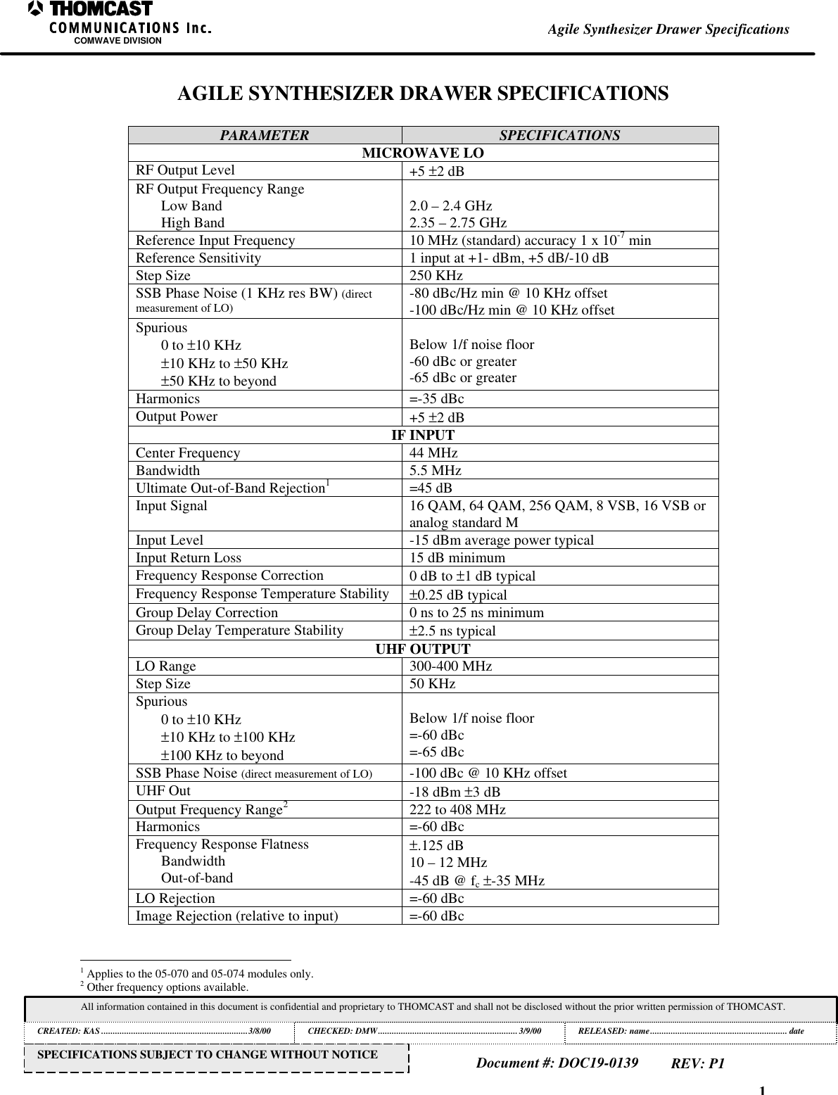
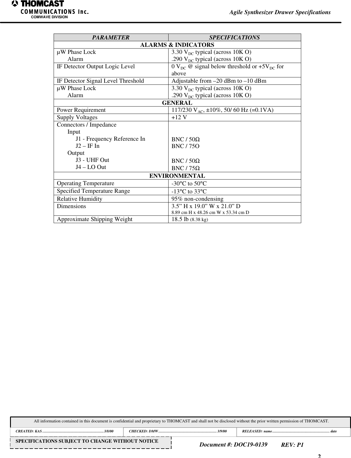
Thomson Broadcast and Multimedia 8BUSDA5000C 50 Watt Frequency Agile Digital Transmitter System User Manual 10 0007 ULPN drawer cover
Thomson Broadcast & Multimedia, Inc. 50 Watt Frequency Agile Digital Transmitter System 10 0007 ULPN drawer cover
Contents
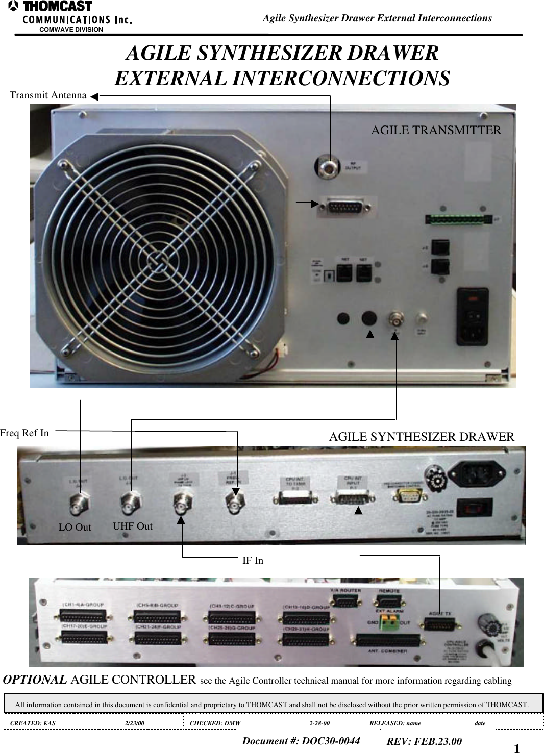
- 1. SDA5000C transmitter
- 2. Agile synthesizer drawer
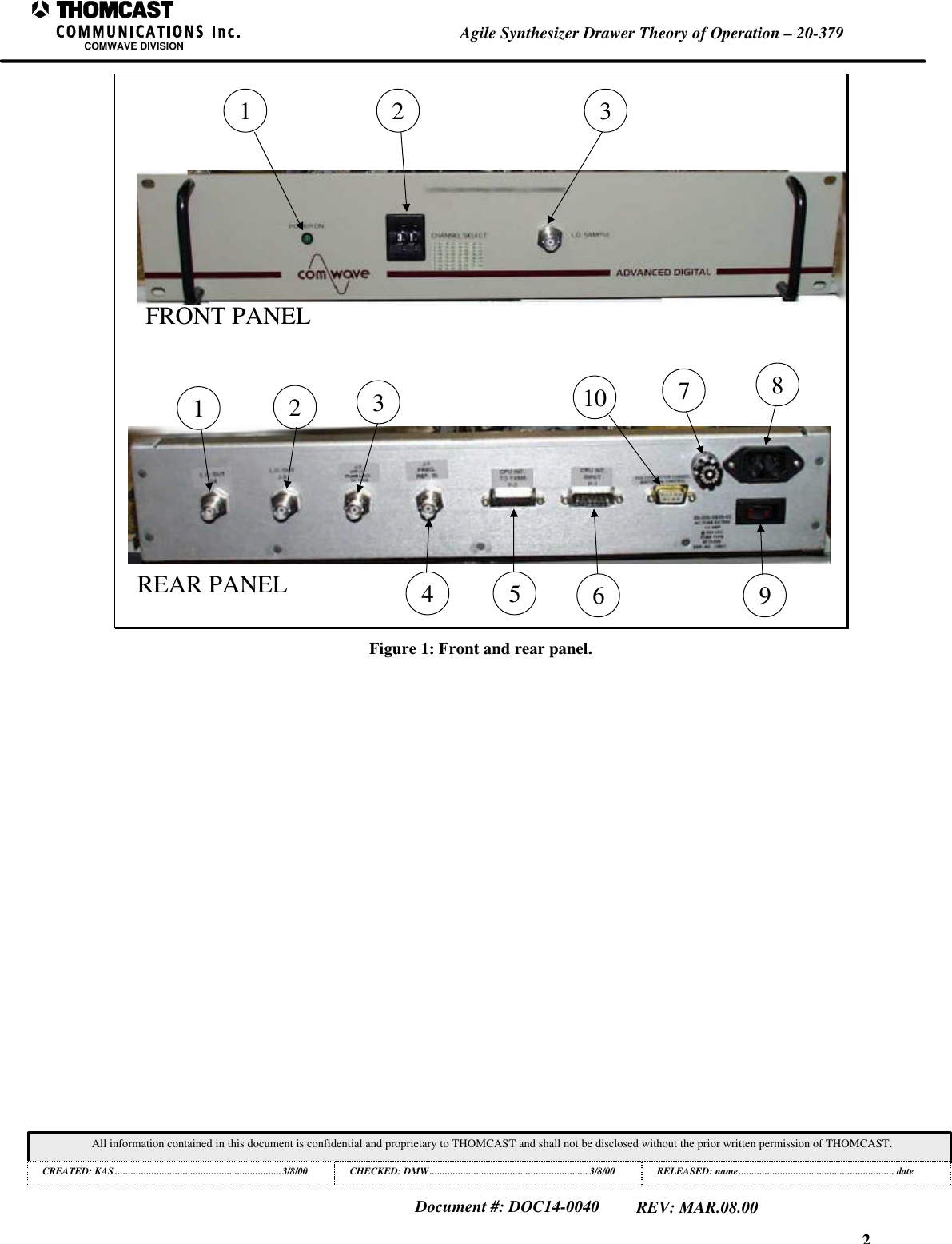
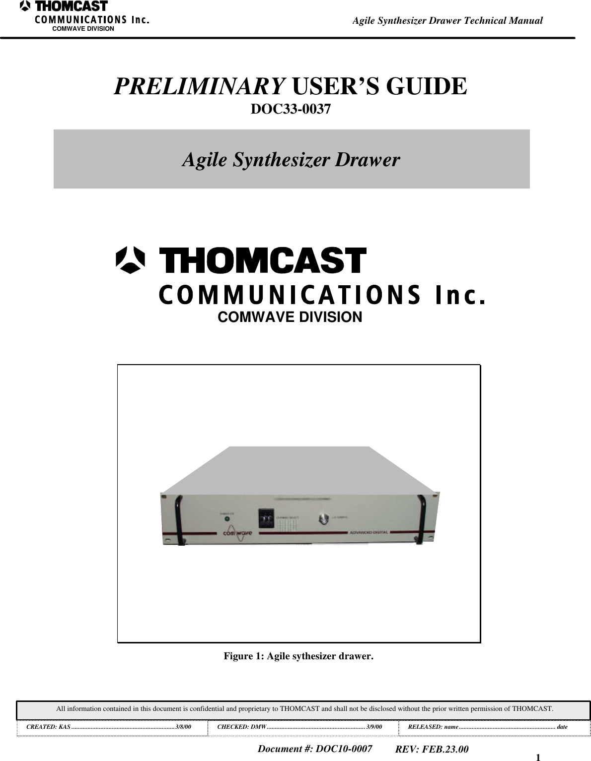
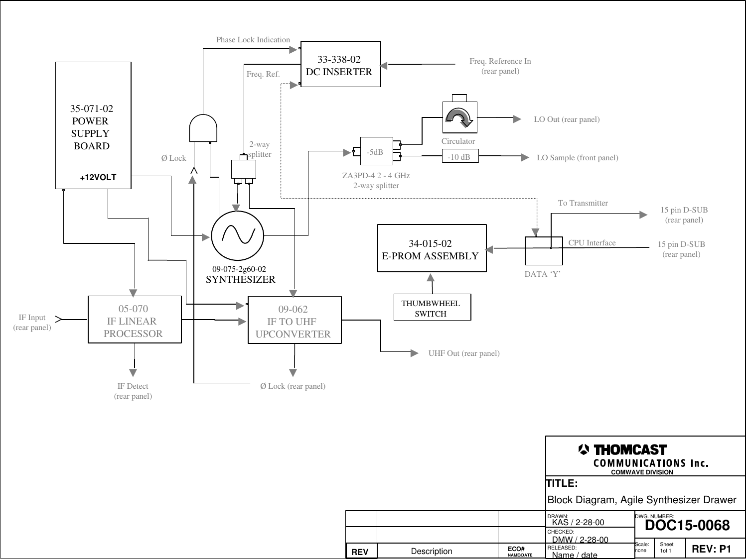
Agile synthesizer drawer
![1COMWAVE DIVISIONAll information contained in this document is confidential and proprietary to THOMCAST and shall not be disclosed without the prior written permission of THOMCAST.CREATED: KAS ................................................................2/23/00 CHECKED: DMW............................................................. 2/28/00RELEASED:......................................................................Document #: DOC26-0053REV: FEB.23.00Turn-On ProcedureTURN-ON PROCEDUREThis section explains the initial turn-on for your chassis and explains normal operation. Prior to equipment turn-on,verify that all appropriate cabling has been accomplished.Turn on1. Ensure the rear mounted main power ON/OFF switch is in the OFF position.2. Insert the power plug into a power outlet.3. Position the main power switch to ON.4. The front panel LED will continuously illuminate green verifying successful turn on and normal operation:OperationSelecting the proper operating channel, as discussed below, and having proper interconnections established betweenthis drawer and all accompanying chassis’ enables operation.Channel Selection / Programming:Channel selection is accomplished in two ways, manually or automatically. Both methods are describedbelow.Manual Channel SelectionManual channel selection is done through the use of the front panel thumbwheel switch. The thumbwheelinterfaces with and EPROM board sending a binary coded decimal (BCD) address to the firmware locatedon the board. The EPROM logic then forwards programming information to the synthesizer in the samemanner. Typical programming results in selection of the lowest channel when the thumbwheel switch isrotated to the [01] position. Progression allows channel selection to move upward in 6 MHz1 steps.Agile Controller InterfaceUpon connection of the Agile Controller, the manual channel setting is overridden. A data ‘Y’ is providedon the DC insertion board. This allows a loop though of logic information in the drawer to the RFprecorrector module located in the upconverter plug-in module. The CPU interface sends a BCD address tothe EPROM board containing the channel selection of the transmitter to be backed up. The EPROM boardthen forwards this programming to the synthesizer module. 1 Channel mapping of A1, B1, A2, B2 ….. G4 is typical, international standards are available.](https://usermanual.wiki/Thomson-Broadcast-and-Multimedia/8BUSDA5000C.Agile-synthesizer-drawer/User-Guide-90828-Page-17.png)