Trine Access Technology 018-4 Hand-Held Pendant Transmitter User Manual 018 4 Instruction Sheet p1 2 ai

Trine Access Technology Hand-Held Pendant Transmitter 018 4 Instruction Sheet p1 2 ai

Exhibit D Users Manual per 2 1033 b3

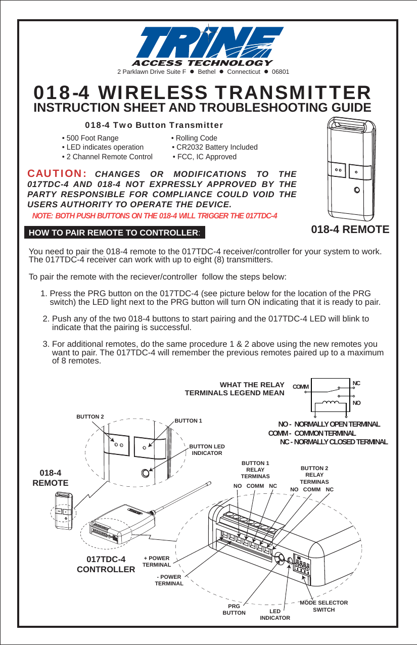
2 Parklawn Drive Suite F    Bethel    Connecticut    06801018-4 WIRELESS TRANSMITTERINSTRUCTION SHEET AND TROUBLESHOOTING GUIDECAUTION: CHANGES OR MODIFICATIONS TO THE 017TDC-4 AND 018-4 NOT EXPRESSLY APPROVED BY THE PARTY RESPONSIBLE FOR COMPLIANCE COULD VOID THE USERS AUTHORITY TO OPERATE THE DEVICE.NOTE: BOTH PUSH BUTTONS ON THE 018-4 WILL TRIGGER THE 017TDC-4HOW TO PAIR REMOTE TO CONTROLLER:You need to pair the 018-4 remote to the 017TDC-4 receiver/controller for your system to work. The 017TDC-4 receiver can work with up to eight (8) transmitters.To pair the remote with the reciever/controller  follow the steps below:     1. Press the PRG button on the 017TDC-4 (see picture below for the location of the PRG          switch) the LED light next to the PRG button will turn ON indicating that it is ready to pair.       2. Push any of the two 018-4 buttons to start pairing and the 017TDC-4 LED will blink to           indicate that the pairing is successful.      3. For additional remotes, do the same procedure 1 & 2 above using the new remotes you           want to pair. The 017TDC-4 will remember the previous remotes paired up to a maximum           of 8 remotes. 018-4 REMOTE        018-4 Two Button Transmitter• 500 Foot Range                          • Rolling Code• LED indicates operation              • CR2032 Battery Included• 2 Channel Remote Control          • FCC, IC ApprovedPRGBUTTONBUTTON 2 BUTTON 1BUTTON LEDINDICATORLEDINDICATORMODE SELECTORSWITCH+ POWERTERMINAL- POWERTERMINALBUTTON 1RELAYTERMINASBUTTON 2RELAYTERMINASNO NCCOMM NO NCCOMM018-4REMOTE017TDC-4CONTROLLER      NO -  NORMALLY OPEN TERMINALCOMM -  COMMON TERMINAL       NC - NORMALLY CLOSED TERMINALNONCCOMMWHAT THE RELAYTERMINALS LEGEND MEAN
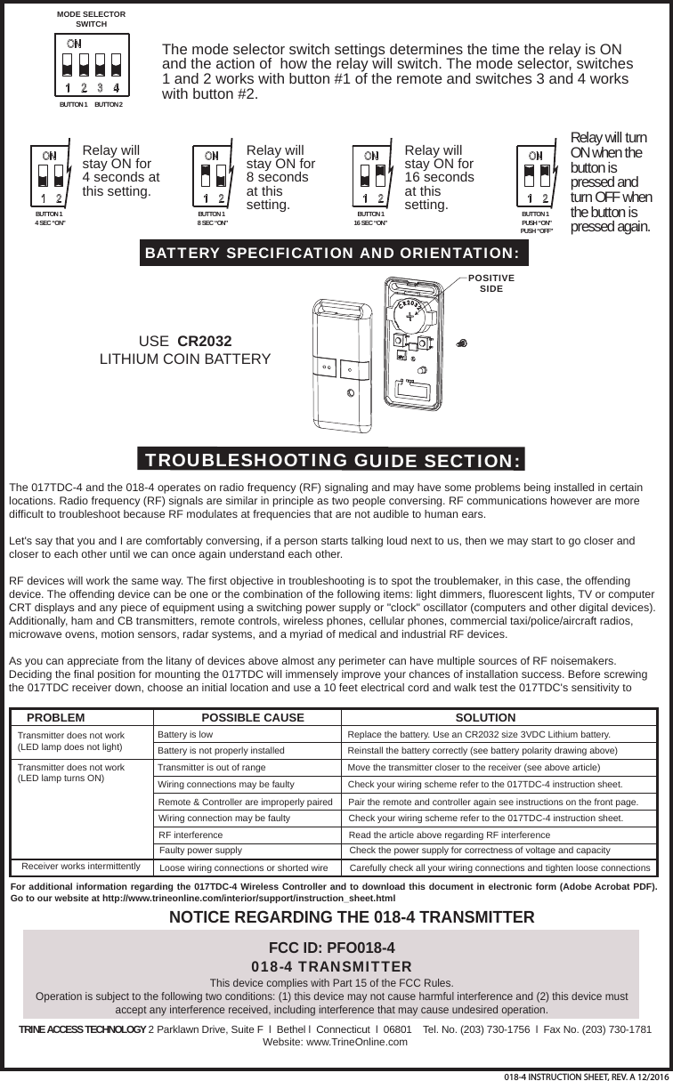
USE  CR2032 LITHIUM COIN BATTERYBATTERY SPECIFICATION AND ORIENTATION:POSITIVESIDEFCC ID: PFO018-4018-4 TRANSMITTERThis device complies with Part 15 of the FCC Rules.Operation is subject to the following two conditions: (1) this device may not cause harmful interference and (2) this device must accept any interference received, including interference that may cause undesired operation. NOTICE REGARDING THE 018-4 TRANSMITTERTROUBLESHOOTING GUIDE SECTION:The 017TDC-4 and the 018-4 operates on radio frequency (RF) signaling and may have some problems being installed in certain locations. Radio frequency (RF) signals are similar in principle as two people conversing. RF communications however are more difficult to troubleshoot because RF modulates at frequencies that are not audible to human ears. Let's say that you and I are comfortably conversing, if a person starts talking loud next to us, then we may start to go closer and closer to each other until we can once again understand each other.RF devices will work the same way. The first objective in troubleshooting is to spot the troublemaker, in this case, the offending device. The offending device can be one or the combination of the following items: light dimmers, fluorescent lights, TV or computer CRT displays and any piece of equipment using a switching power supply or "clock" oscillator (computers and other digital devices). Additionally, ham and CB transmitters, remote controls, wireless phones, cellular phones, commercial taxi/police/aircraft radios, microwave ovens, motion sensors, radar systems, and a myriad of medical and industrial RF devices.As you can appreciate from the litany of devices above almost any perimeter can have multiple sources of RF noisemakers. Deciding the final position for mounting the 017TDC will immensely improve your chances of installation success. Before screwing the 017TDC receiver down, choose an initial location and use a 10 feet electrical cord and walk test the 017TDC's sensitivity to PROBLEM POSSIBLE CAUSE SOLUTIONTransmitter does not work(LED lamp does not light)Transmitter does not work(LED lamp turns ON)Receiver works intermittentlyBattery is lowBattery is not properly installed Transmitter is out of range Wiring connections may be faulty Remote & Controller are improperly paired Wiring connection may be faulty RF interference Faulty power supply Loose wiring connections or shorted wire Replace the battery. Use an CR2032 size 3VDC Lithium battery.Reinstall the battery correctly (see battery polarity drawing above)Move the transmitter closer to the receiver (see above article)Check your wiring scheme refer to the 017TDC-4 instruction sheet.Pair the remote and controller again see instructions on the front page.Check your wiring scheme refer to the 017TDC-4 instruction sheet. Read the article above regarding RF interference Check the power supply for correctness of voltage and capacity Carefully check all your wiring connections and tighten loose connections For additional information regarding the 017TDC-4 Wireless Controller and to download this document in electronic form (Adobe Acrobat PDF). Go to our website at http://www.trineonline.com/interior/support/instruction_sheet.htmlTRINE ACCESS TECHNOLOGY 2 Parklawn Drive, Suite F  l  Bethel l  Connecticut  l  06801    Tel. No. (203) 730-1756  l  Fax No. (203) 730-1781Website: www.TrineOnline.comBUTTON 1 BUTTON 2MODE SELECTORSWITCHThe mode selector switch settings determines the time the relay is ON and the action of  how the relay will switch. The mode selector, switches 1 and 2 works with button #1 of the remote and switches 3 and 4 works with button #2.BUTTON 14 SEC “ON”BUTTON 18 SEC “ON”Relay will stay ON for 4 seconds at this setting.Relay will stay ON for 8 seconds at this setting. BUTTON 116 SEC “ON”Relay will stay ON for 16 seconds at this setting. BUTTON 1PUSH “ON”PUSH “OFF”Relay will turn ON when the button is pressed and turn OFF when the button is pressed again.018-4 INSTRUCTION SHEET, REV. A 12/2016

Navigation menu