Universal Avionics Systems 10801 Avionics Communication Management Unit User Manual 23 20 06x
Universal Avionics Systems Corporation Avionics Communication Management Unit 23 20 06x
Contents
- 1. Users Manual 1
- 2. Users Manual 3
- 3. Users Manual 4
- 4. Users Manual 5
- 5. Users Manual 6
Users Manual 6
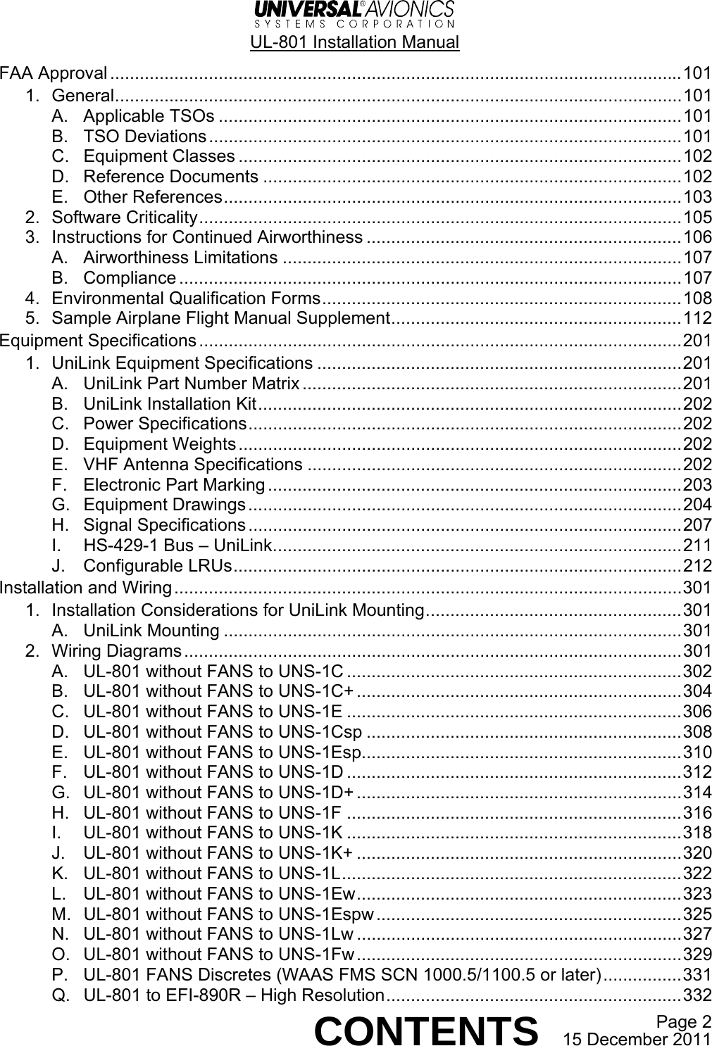
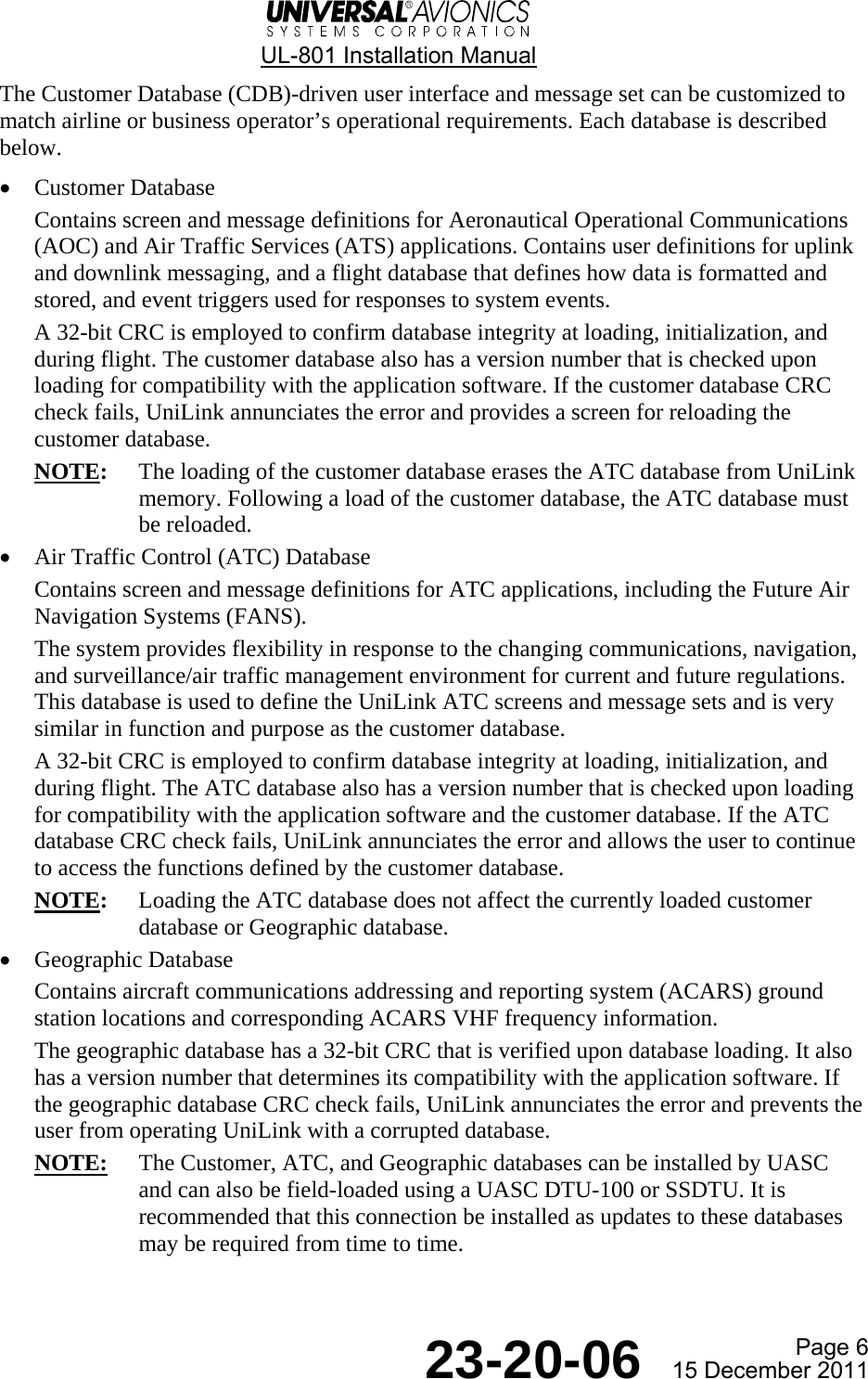
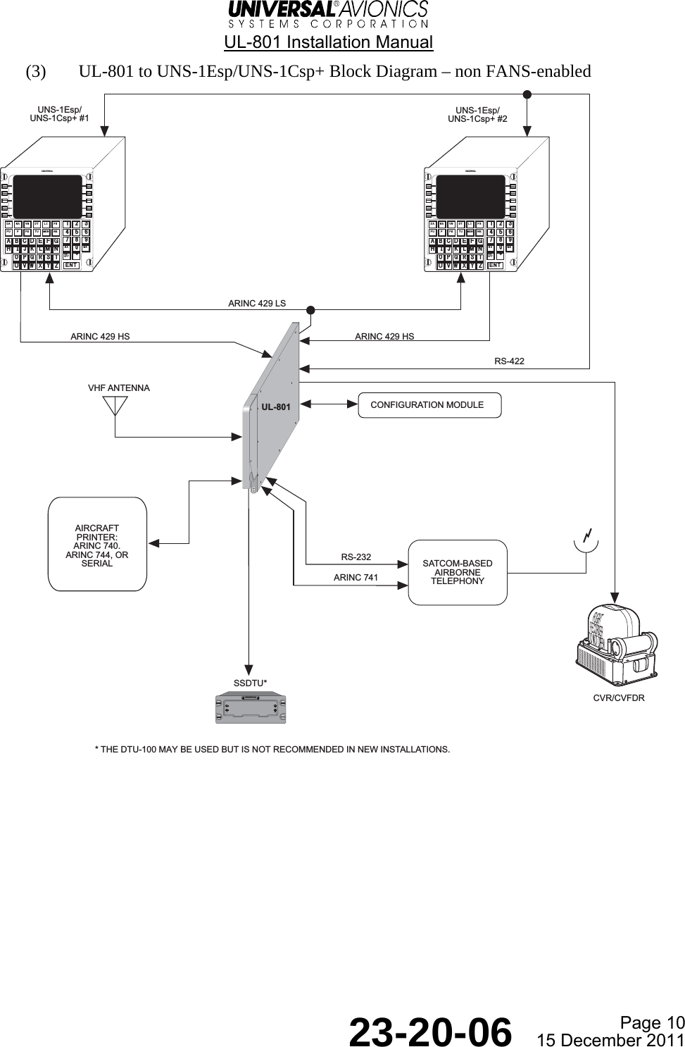
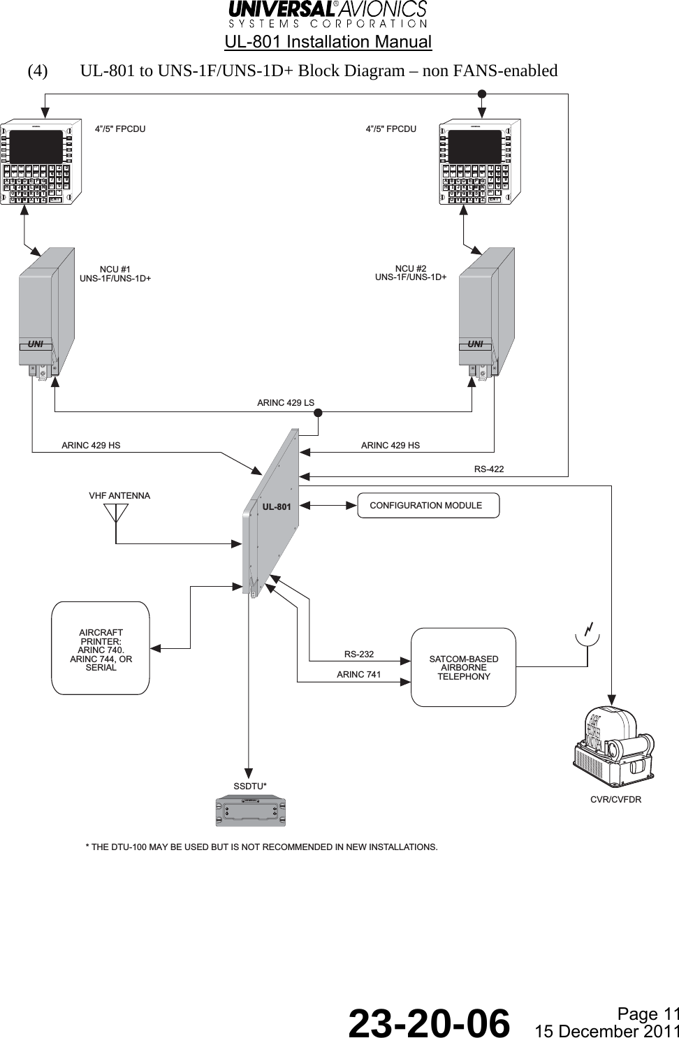
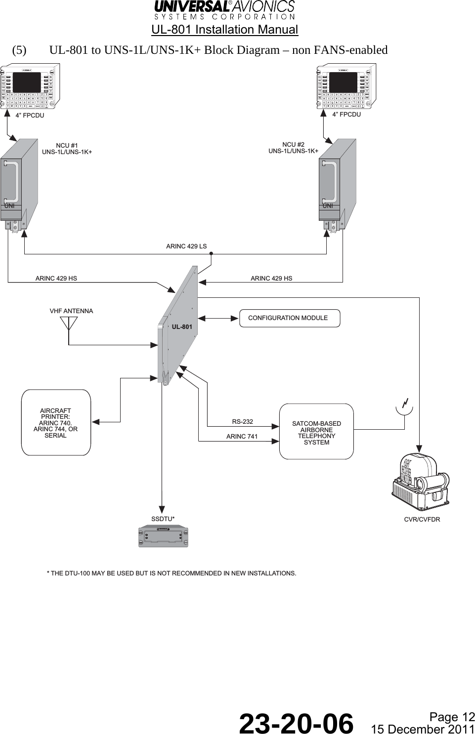
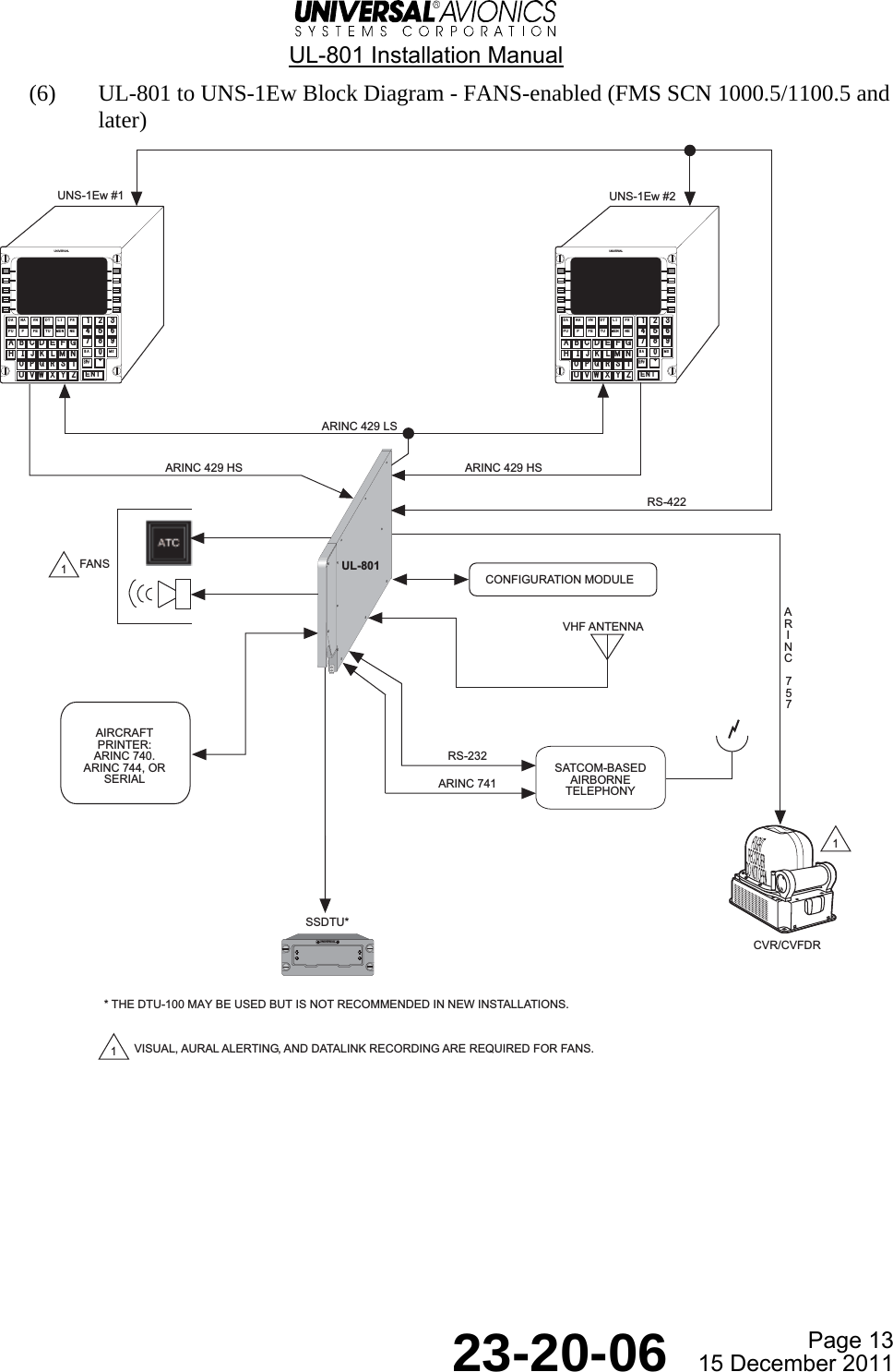
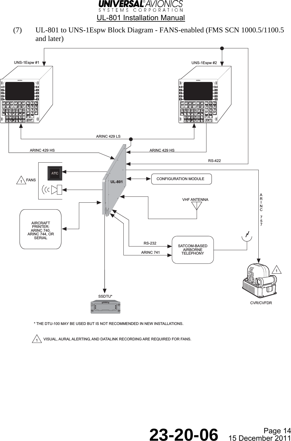
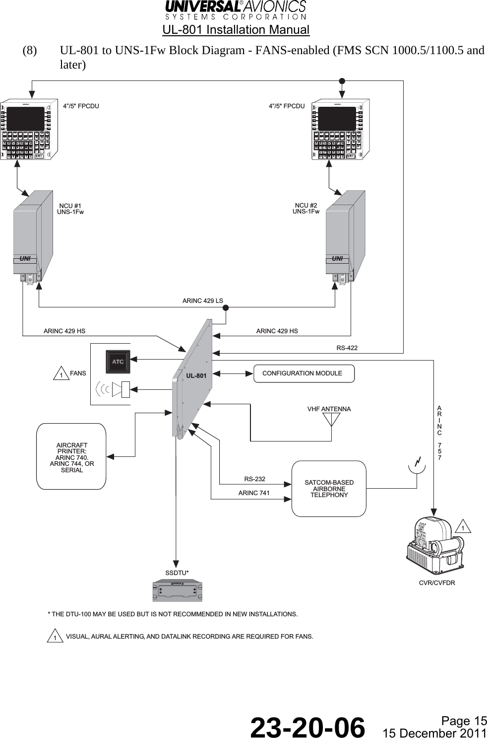
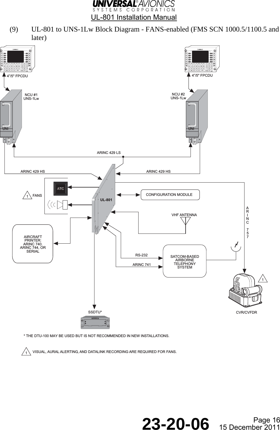
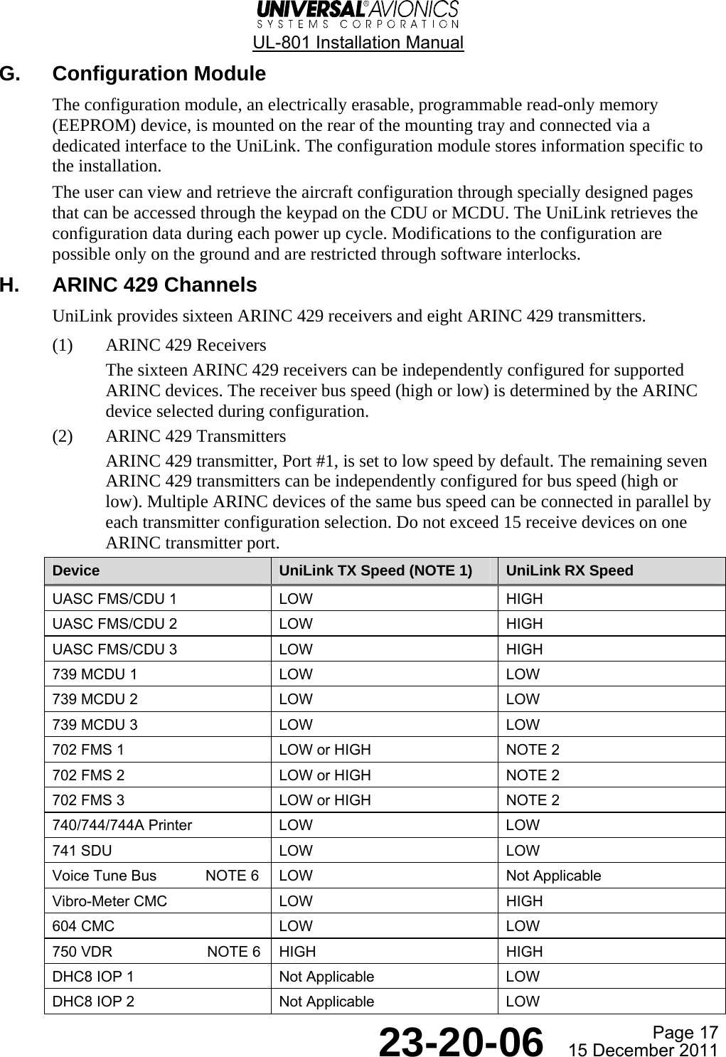
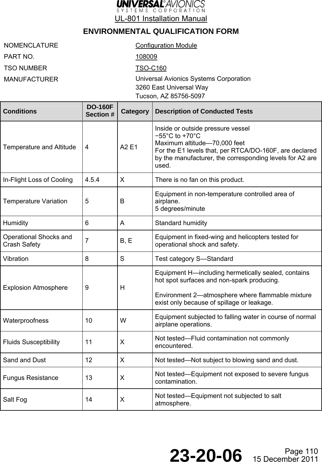
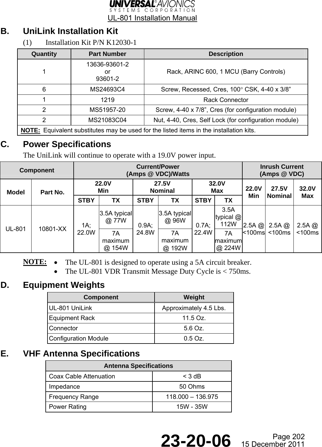
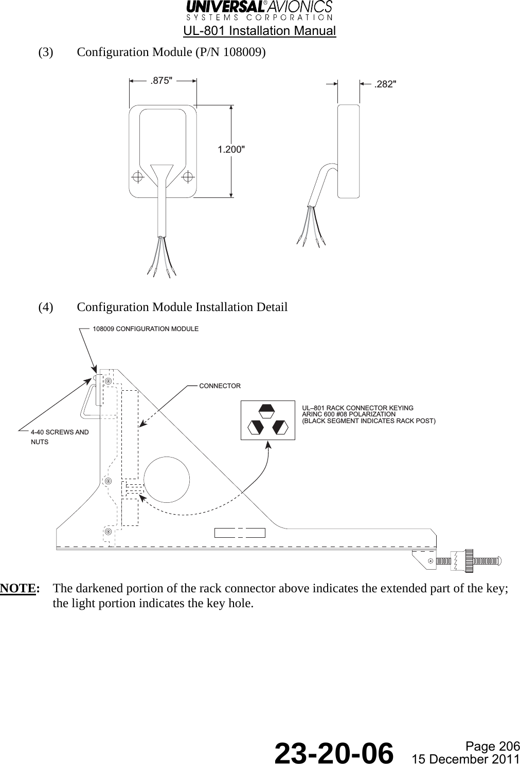
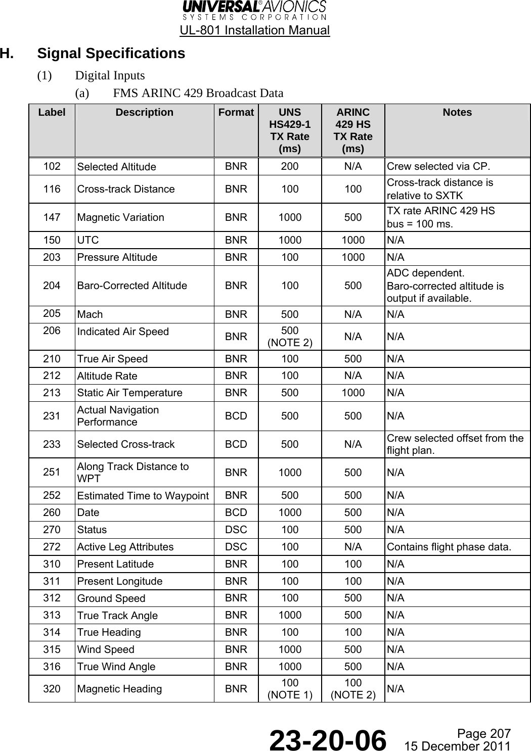
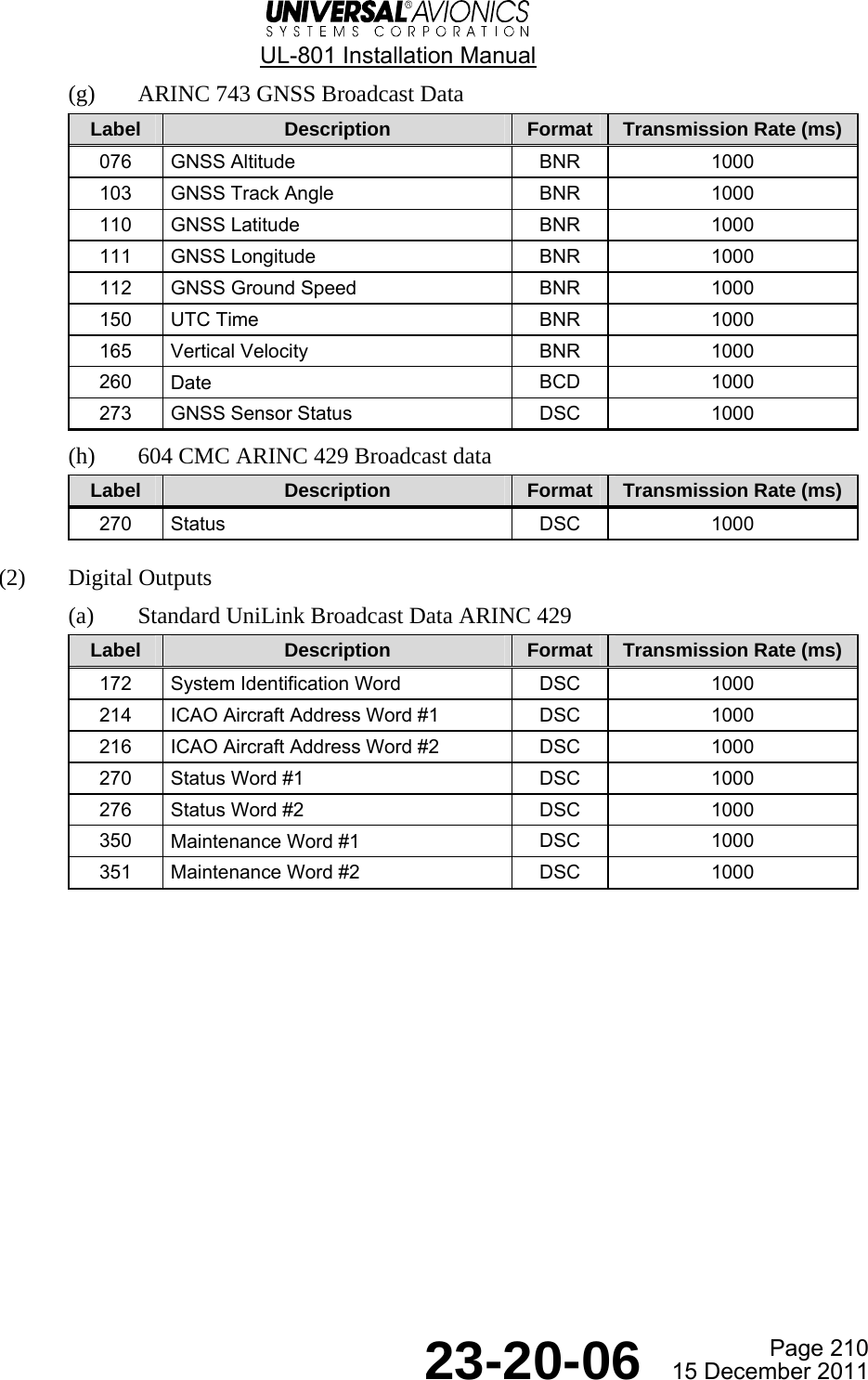
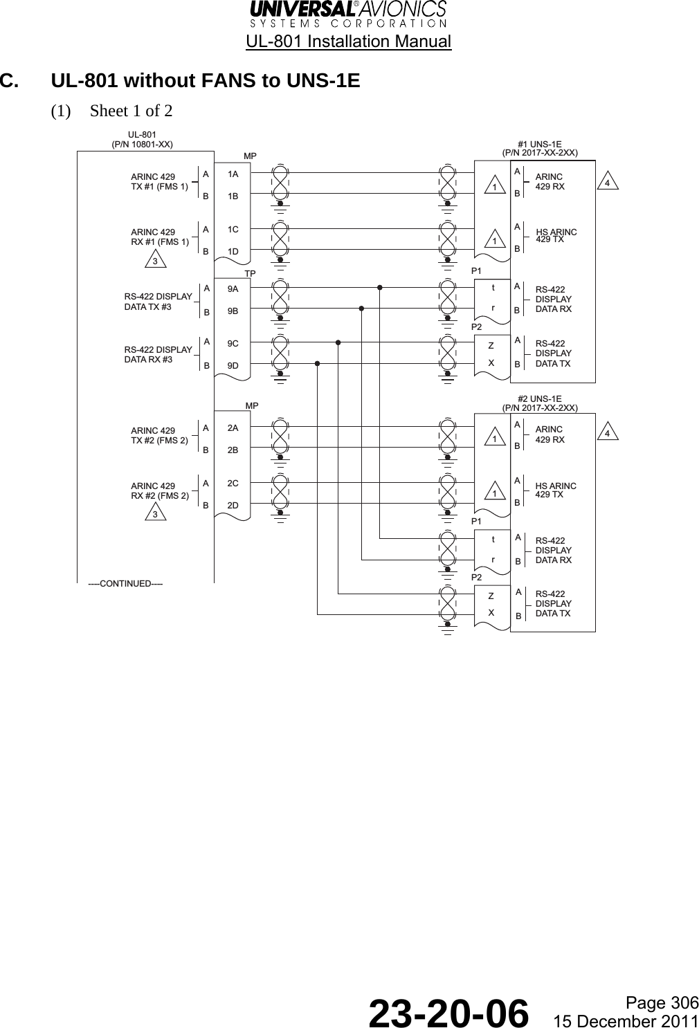
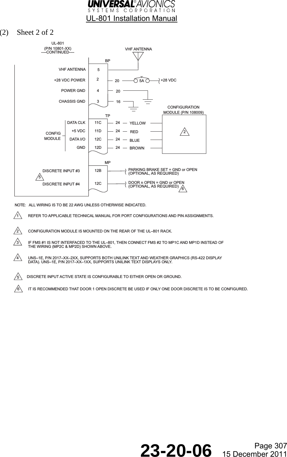
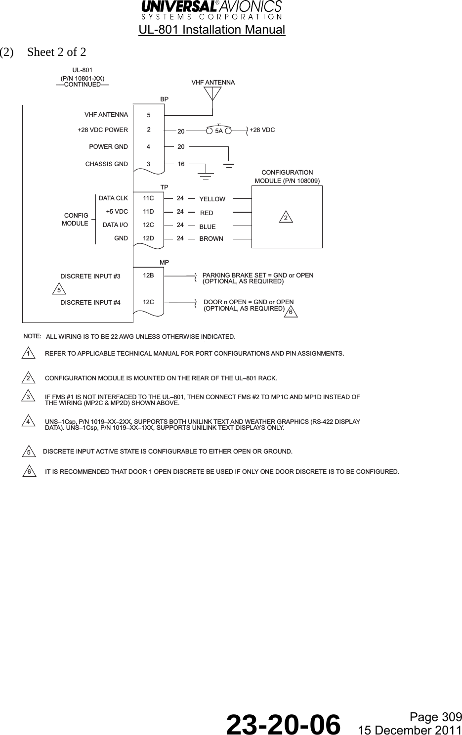
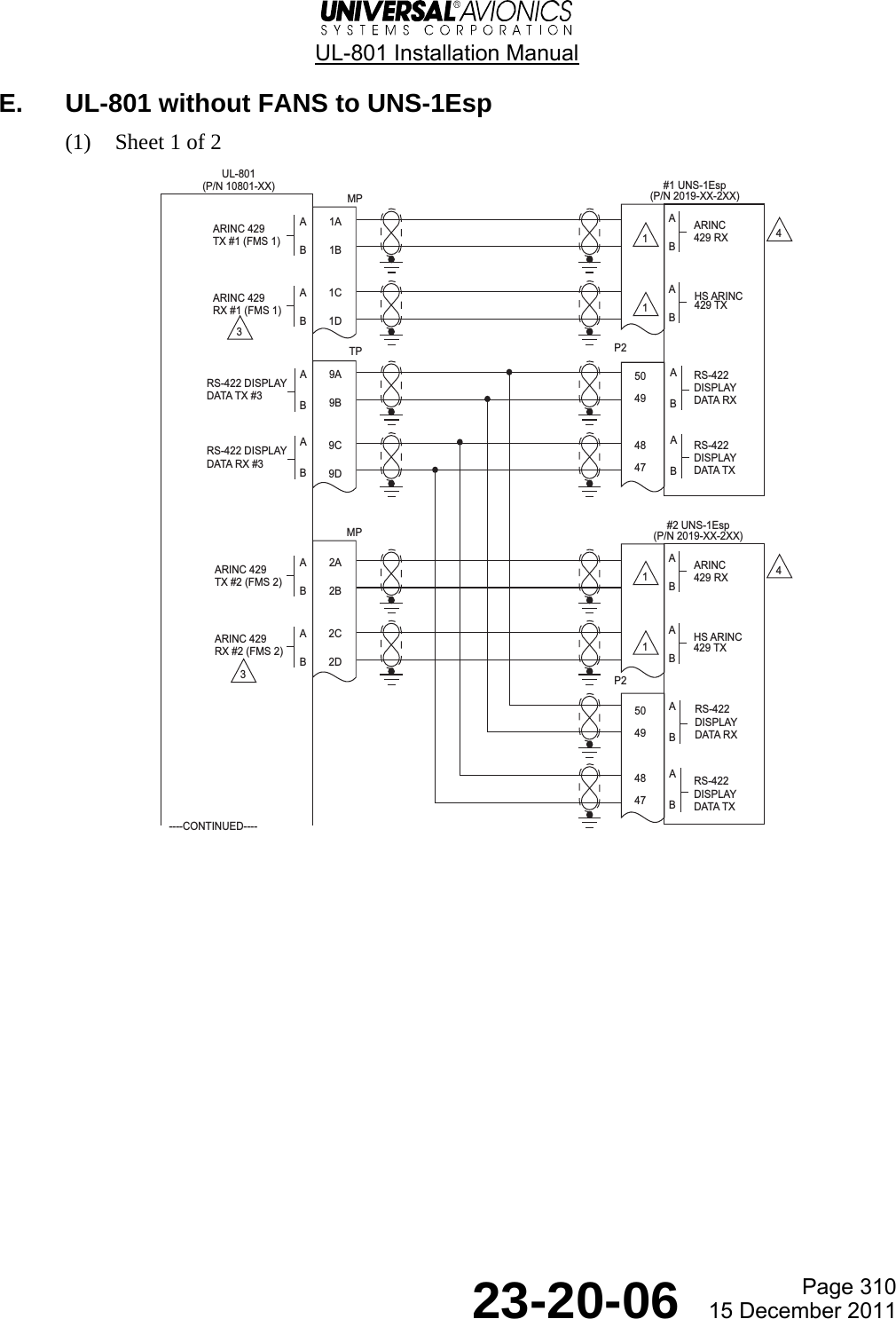
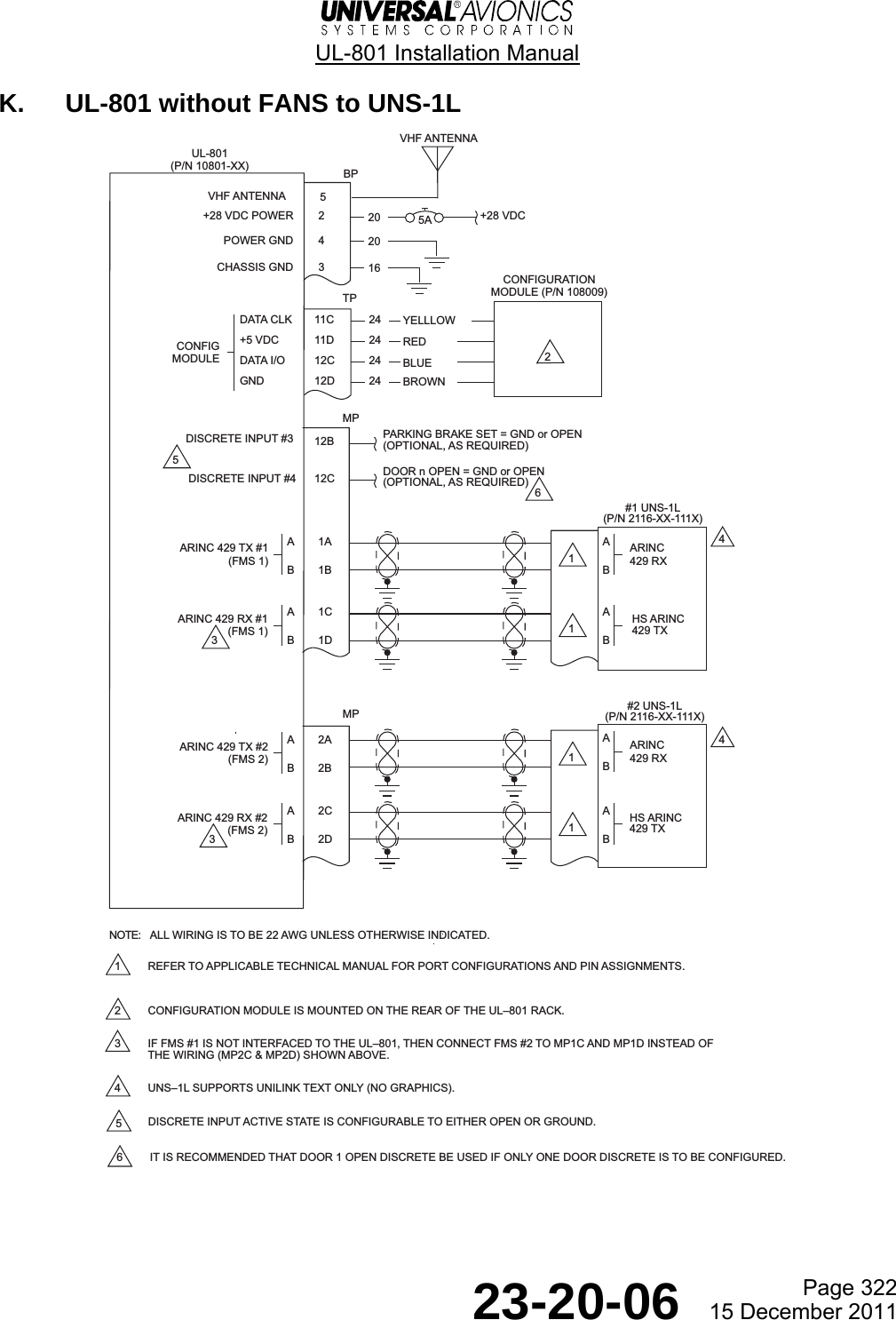
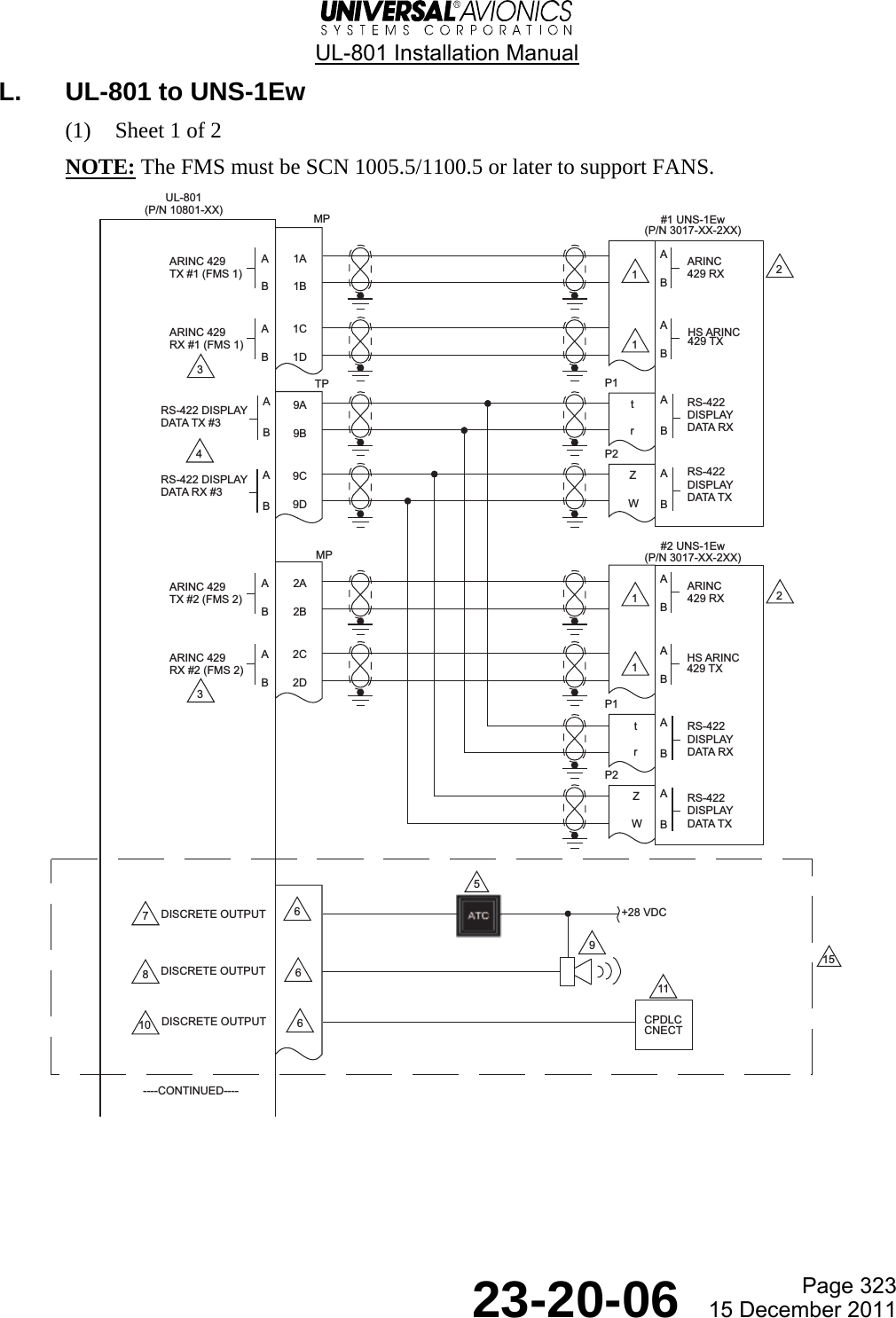
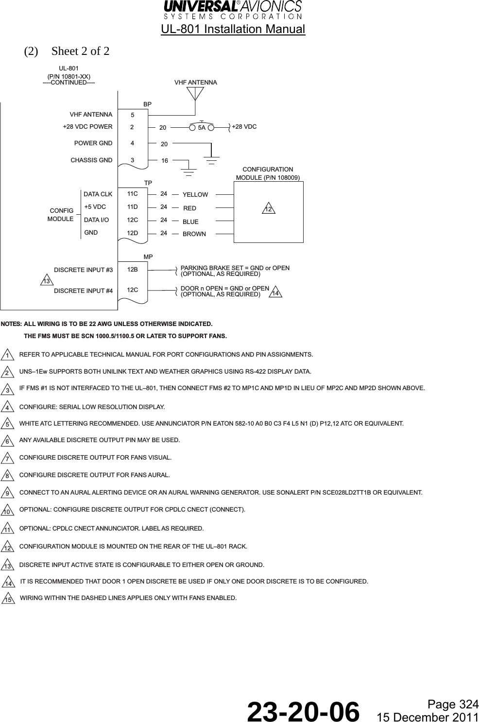
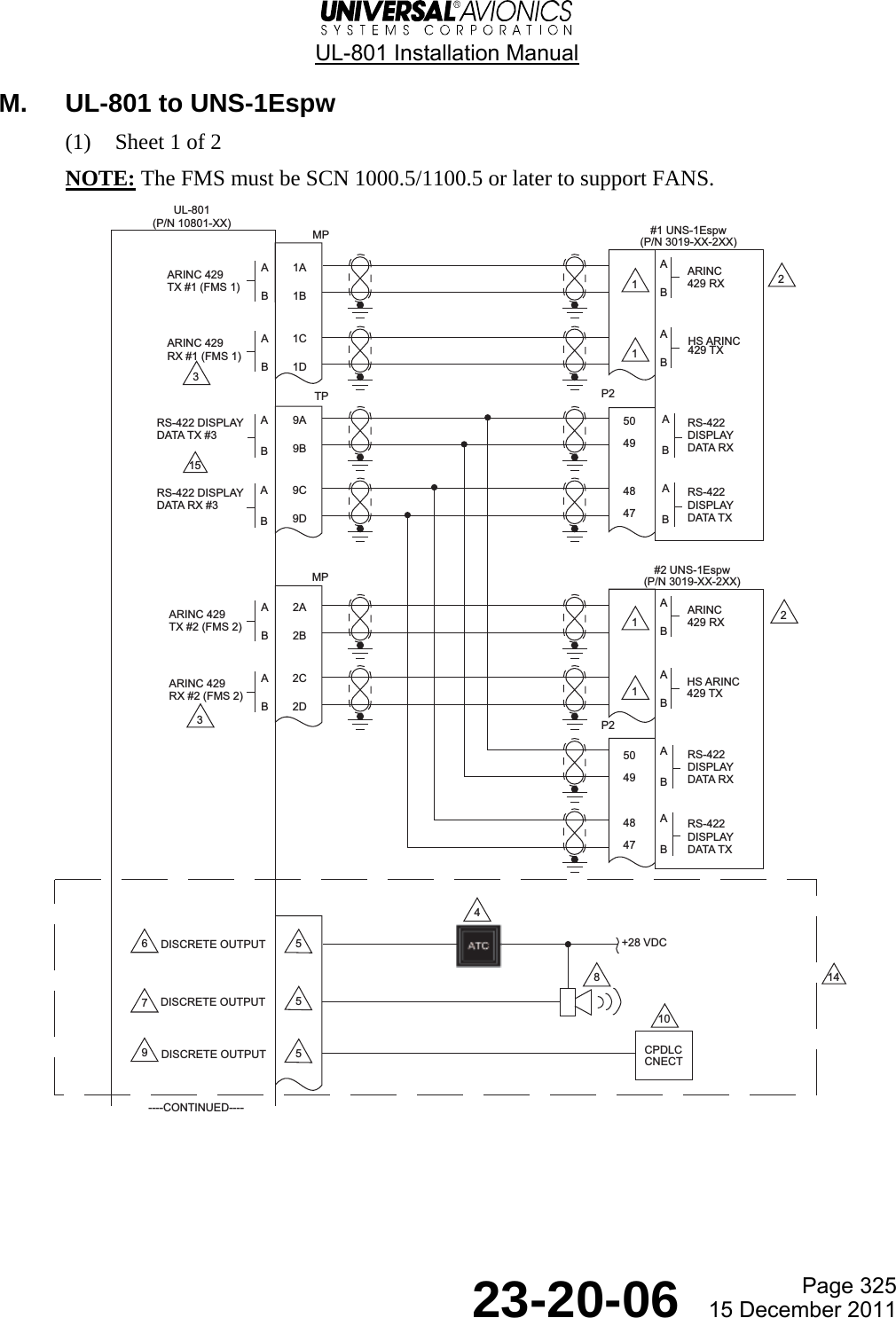
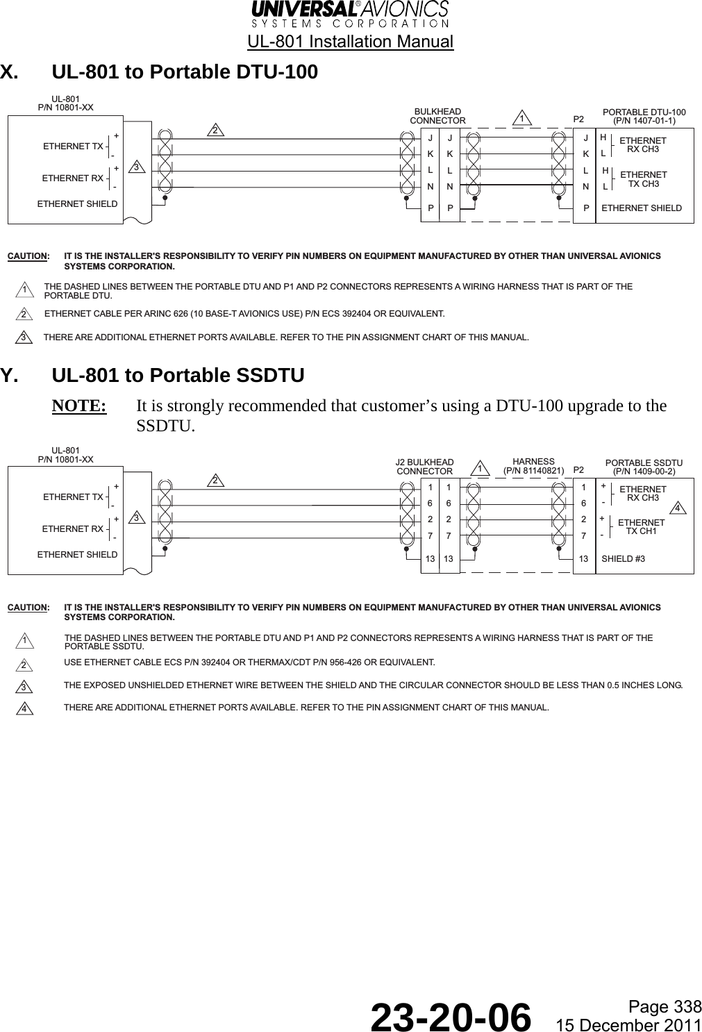
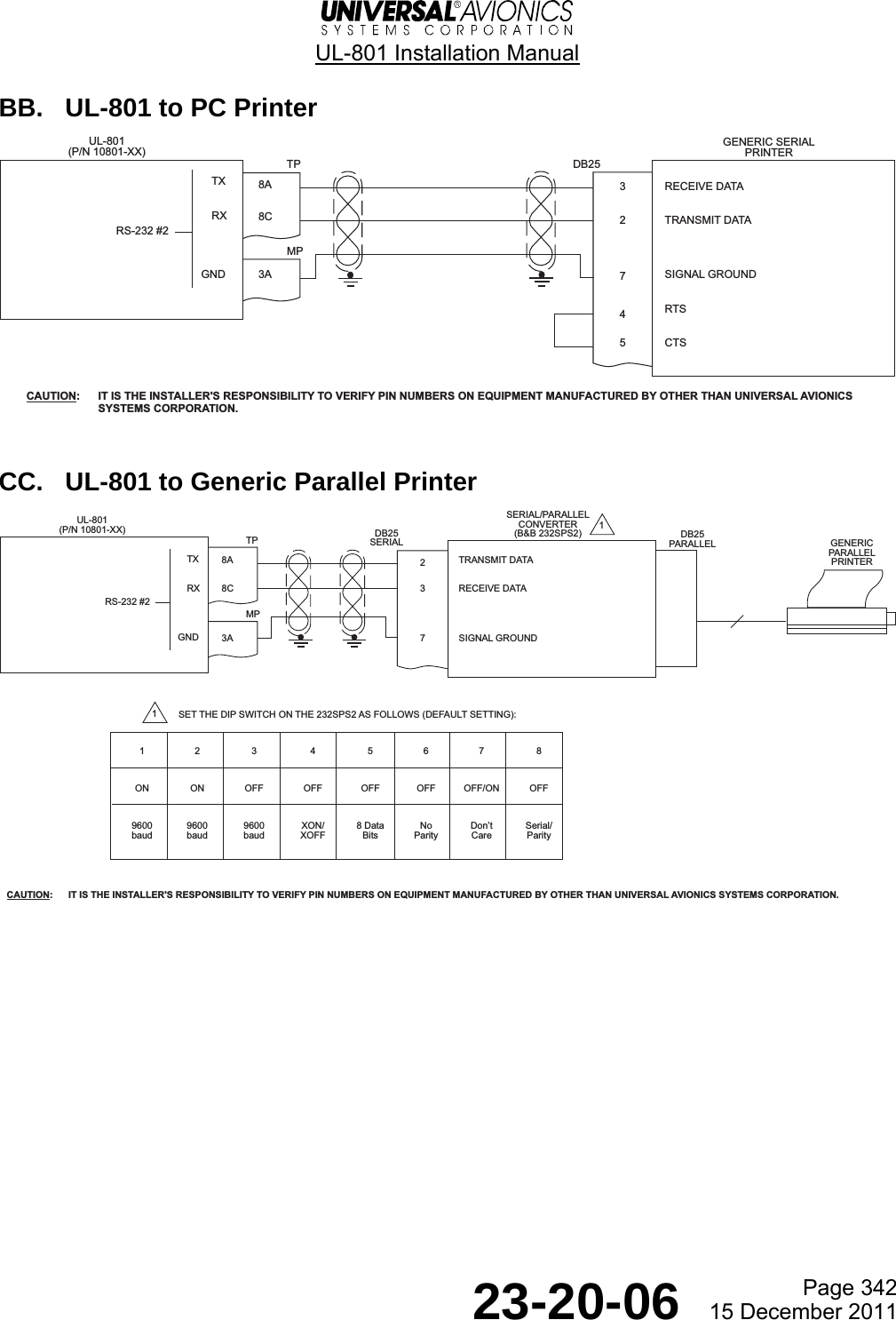
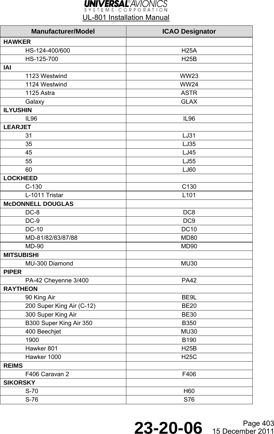
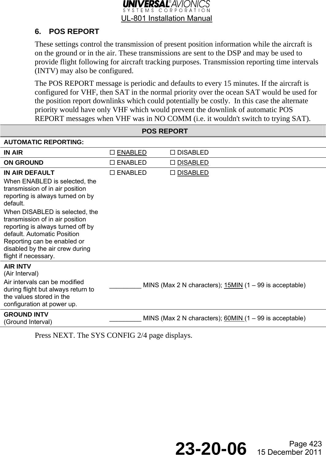
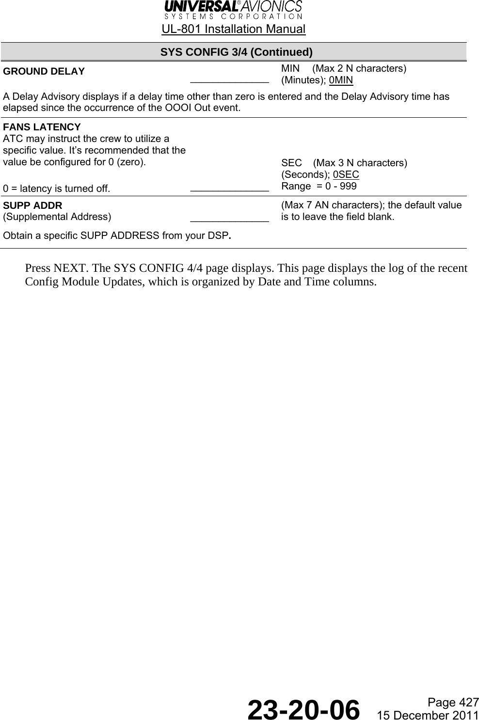
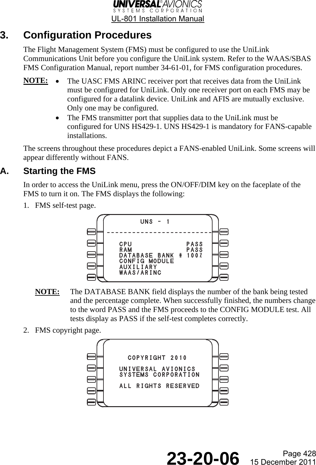
![UL-801 Installation Manual Page 1 23-20-06 15 December 2011 Introduction 1. Makeup and Use of This Manual A. Application This manual provides installation information pertaining to the UL-801. B. Organization This manual provides information about: • Description of the components of the UL-801 • Environmental qualification forms • UniLink equipment specifications • Installation and wiring requirements • Worksheets and procedures for installing system data including configuring the UL-801 Configuration Module 2. Abbreviations and Terminology This manual contains no abbreviations or terms that have varying interpretations throughout the industry. Refer to Appendix 1 for a list of acronyms, abbreviations, and terms that are used throughout this manual. The front panel of the Control Display Unit/Multi-function Control Display Unit (CDU/MCDU), part of the FMS, contains an array of push buttons or keys that are used by the crew to operate the system. Instructions in this manual refer to specific keys by name. We bracket the legend on the key in the text. Examples: [ENTER], [A]. Line Select Keys (LSK) are referred to by numerical order (top to bottom) and side. Text appearing on the display may be included. Example: RETURN [5R]. 3. Contact Information Please submit comments, suggestions, errors or other concerns about this manual to our Technical Publications Department at techpubs@uasc.com. To order copies or request changes in address and distribution information, contact info@uasc.com. For technical questions, please contact customersupport@uasc.com](https://usermanual.wiki/Universal-Avionics-Systems/10801.Users-Manual-6/User-Guide-1641691-Page-15.png)
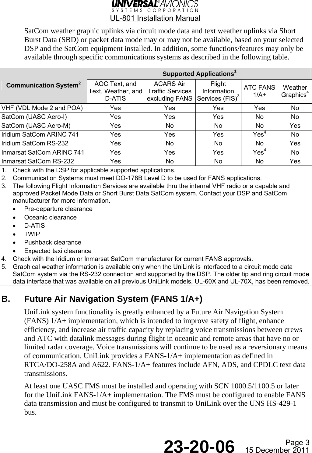
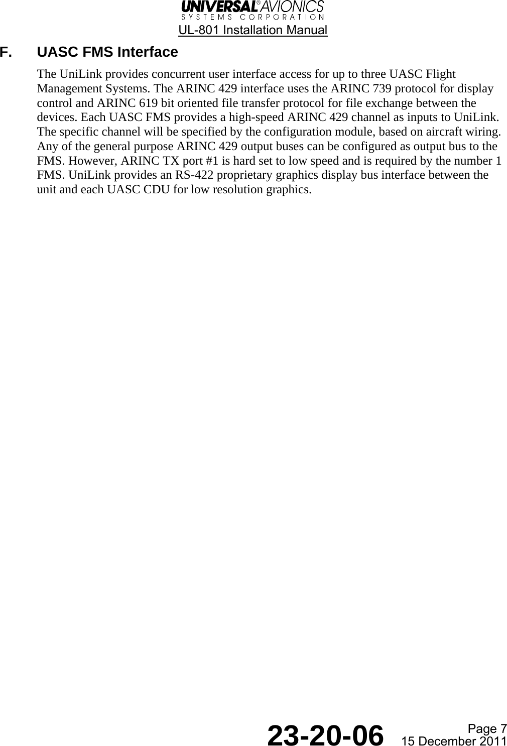
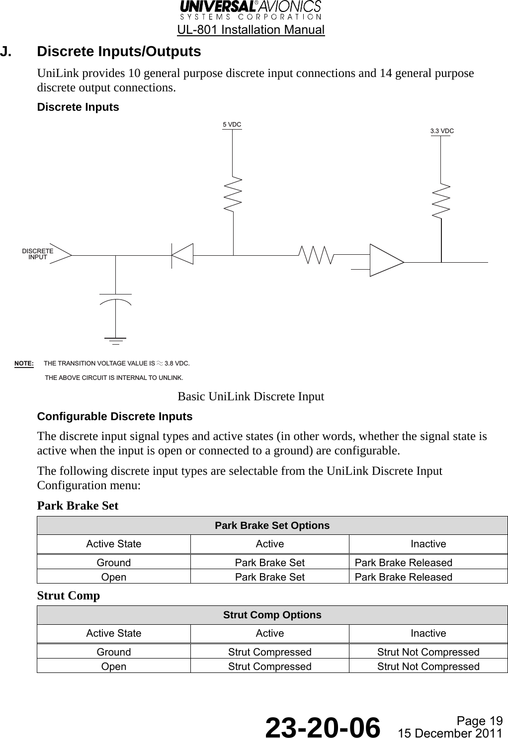
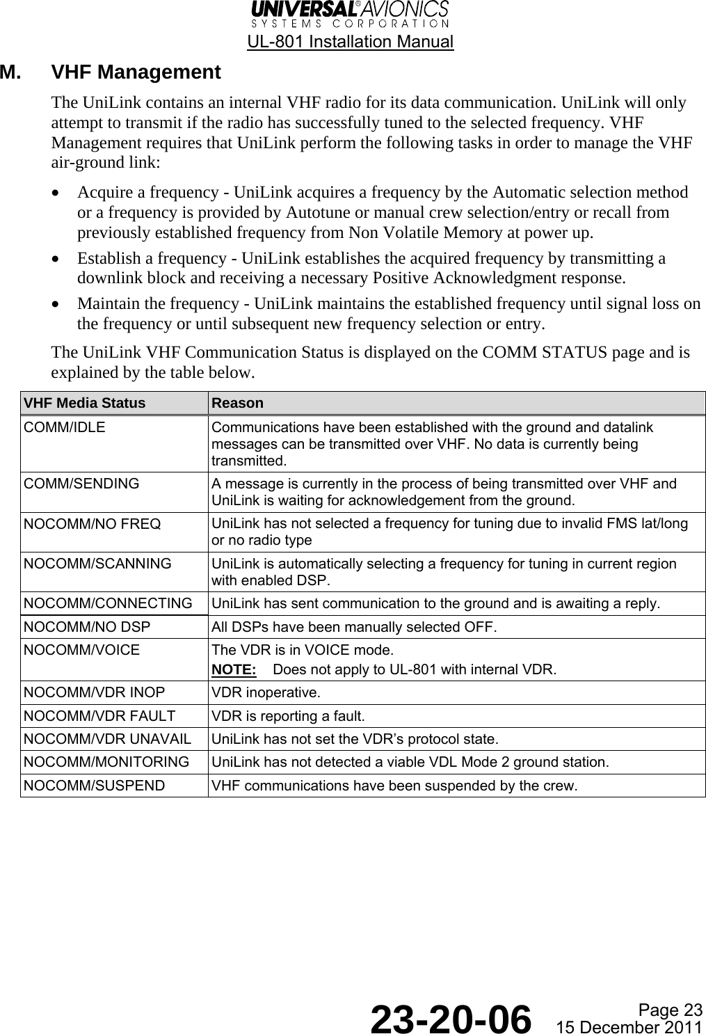
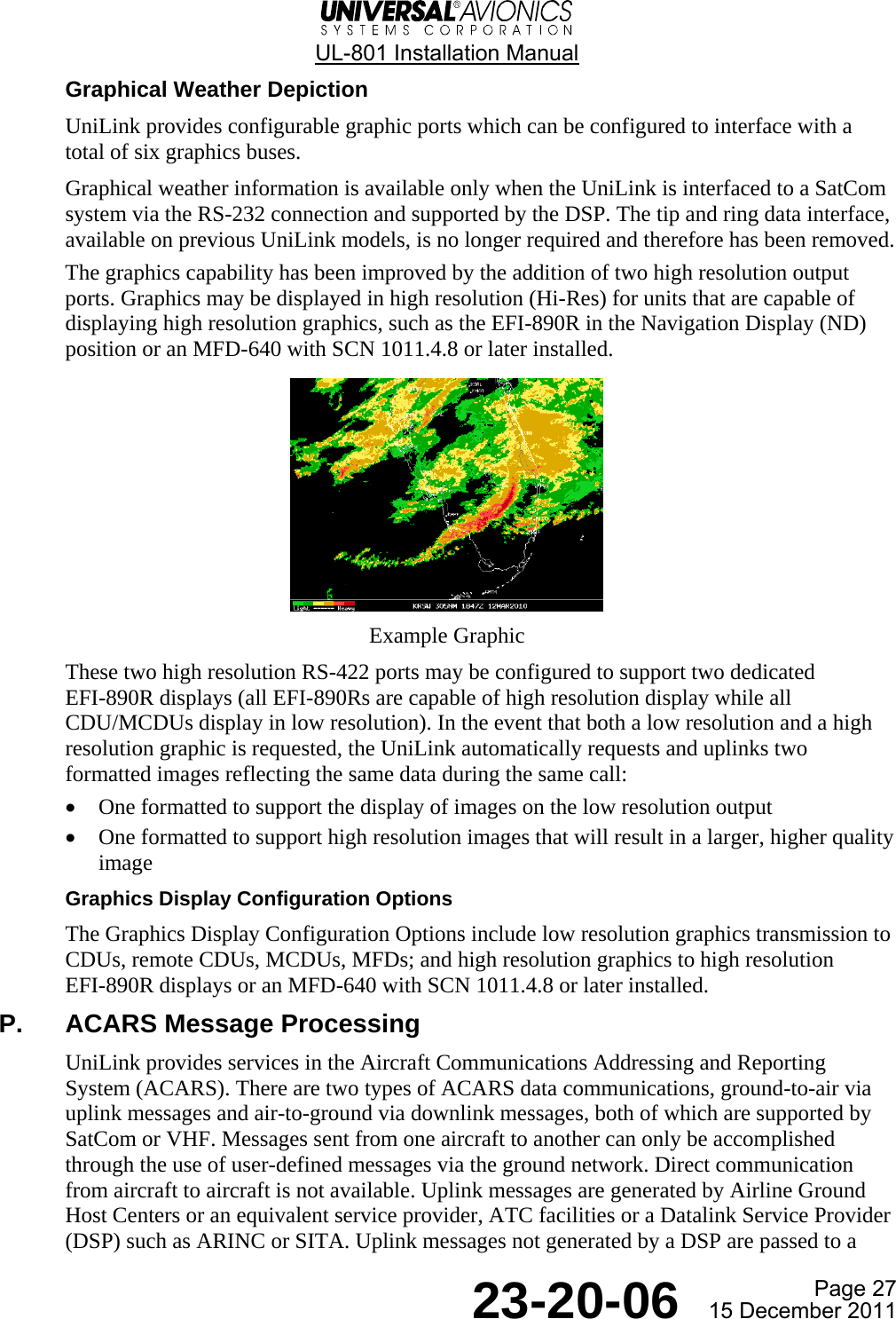
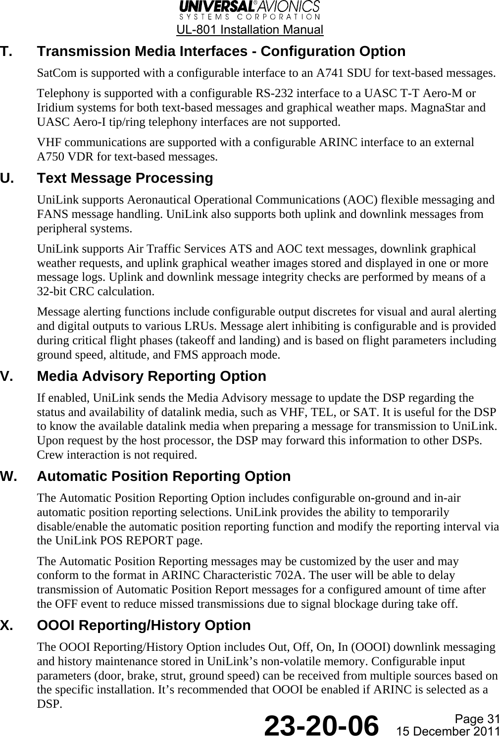
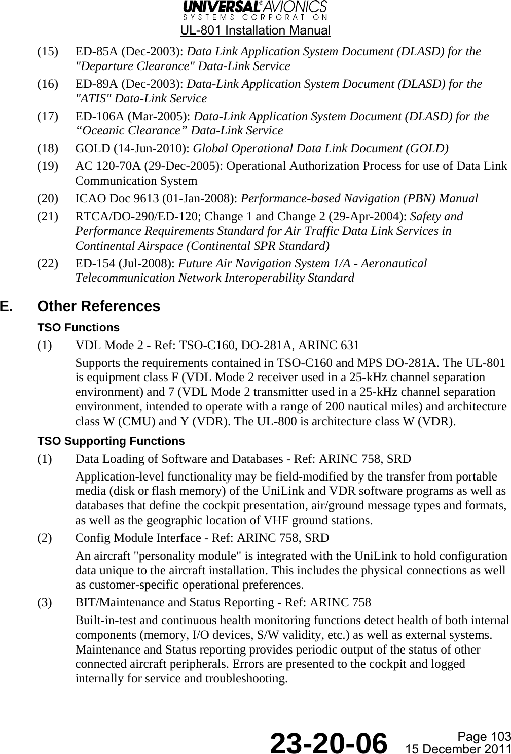
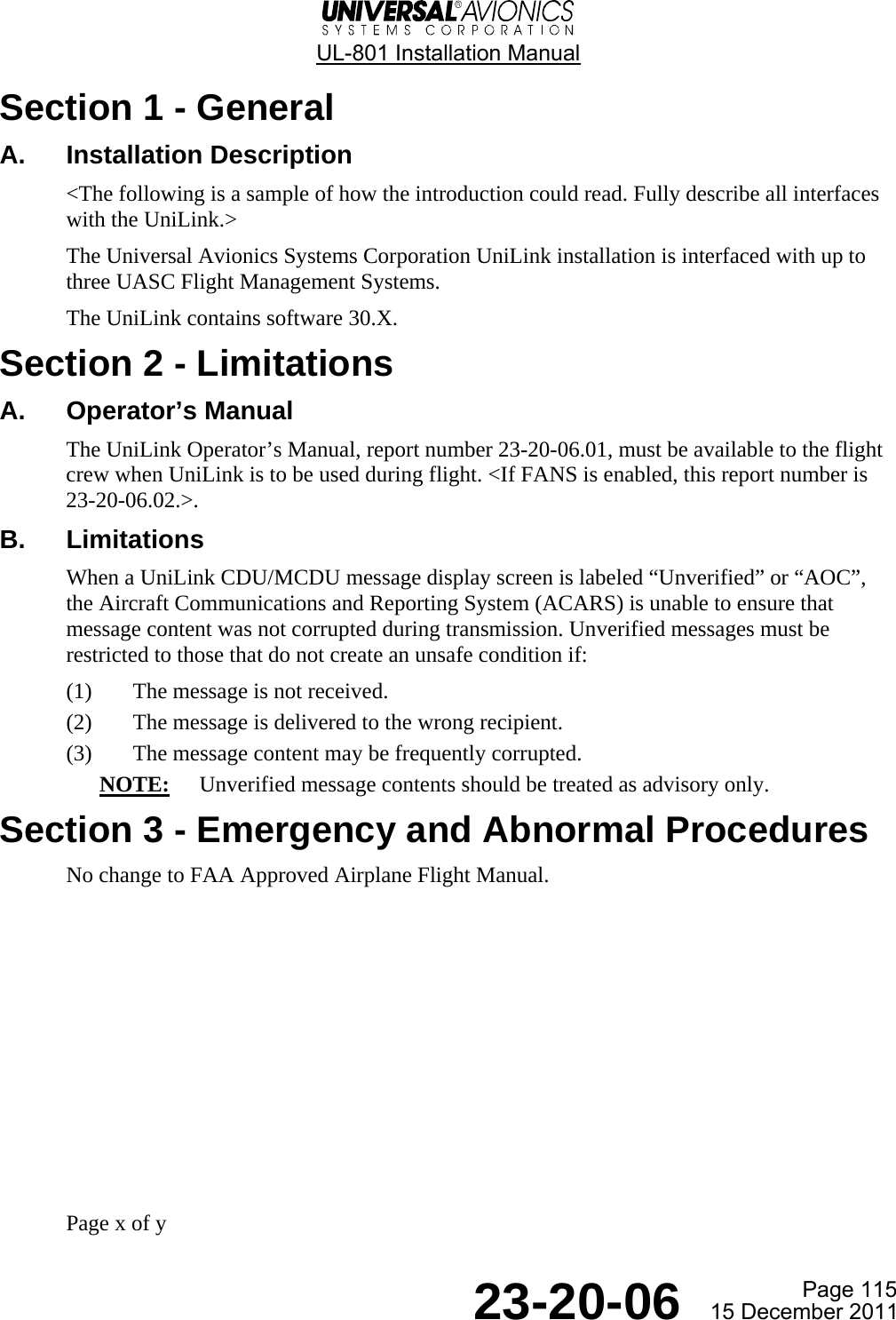
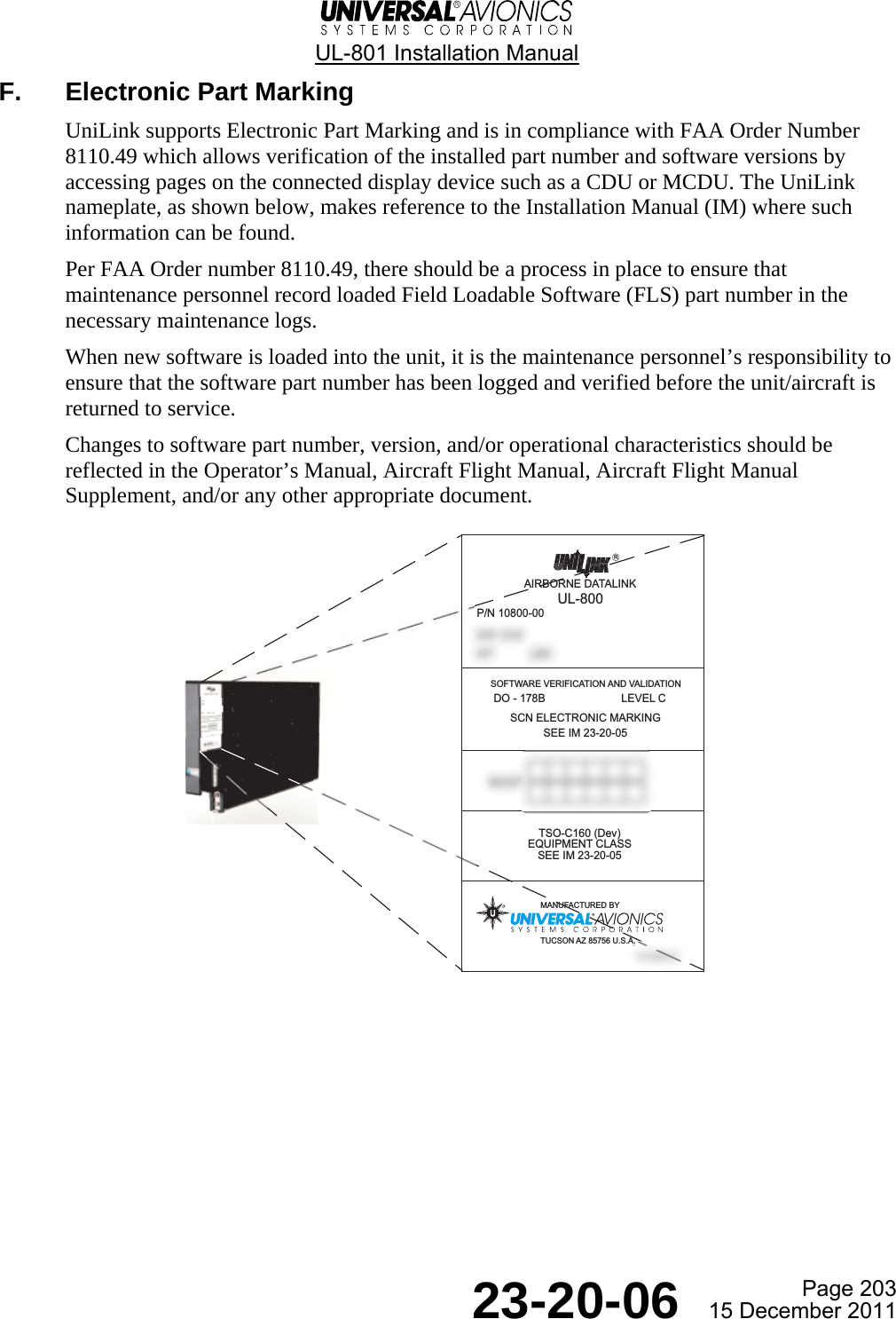
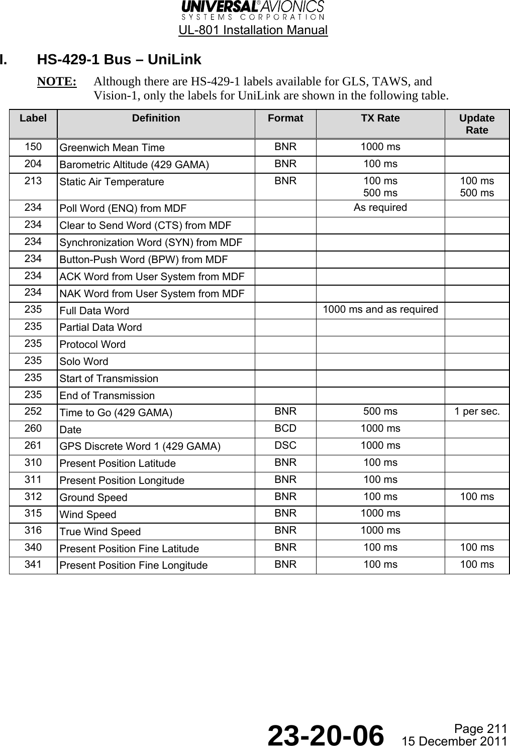


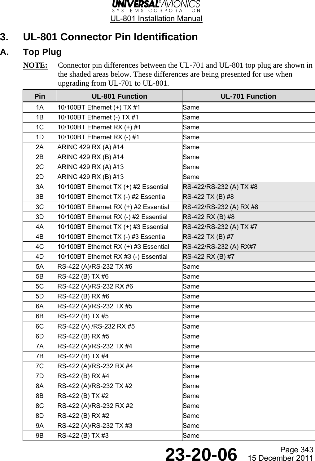
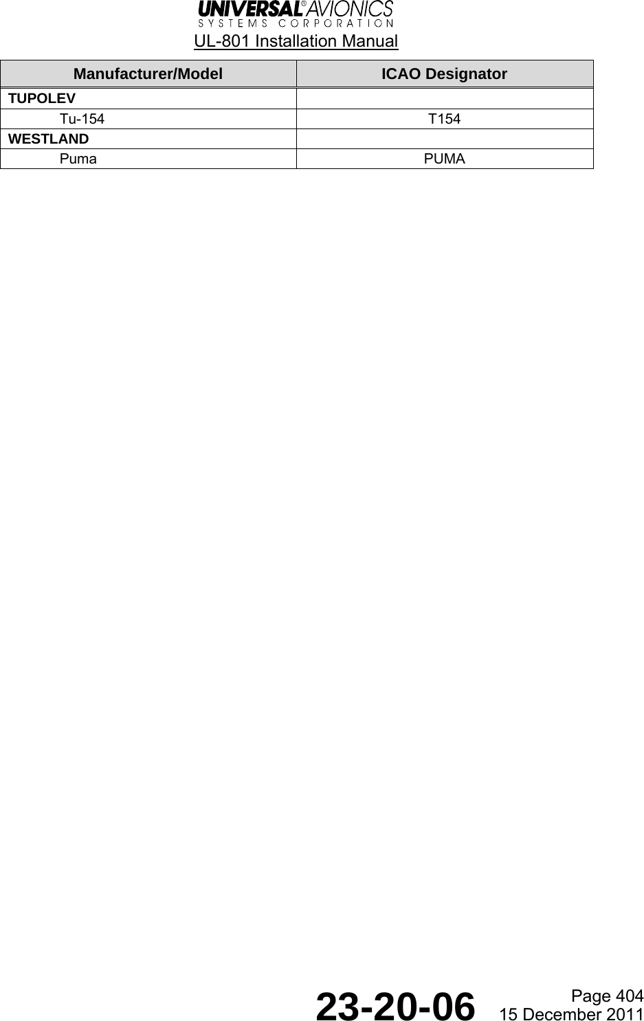
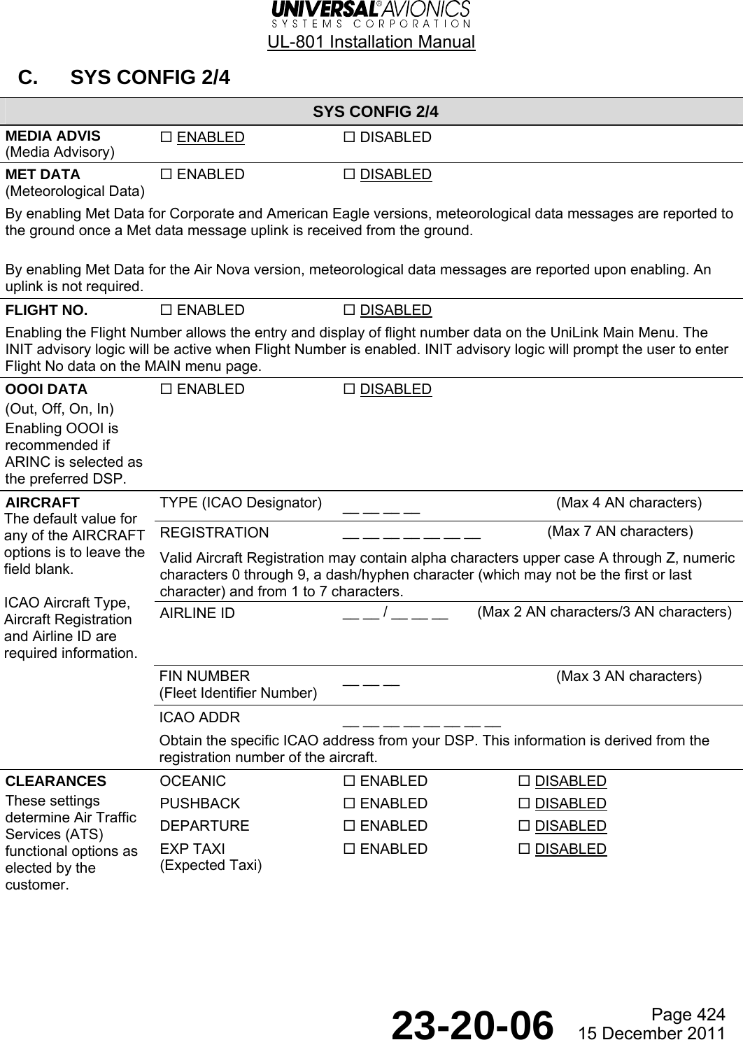
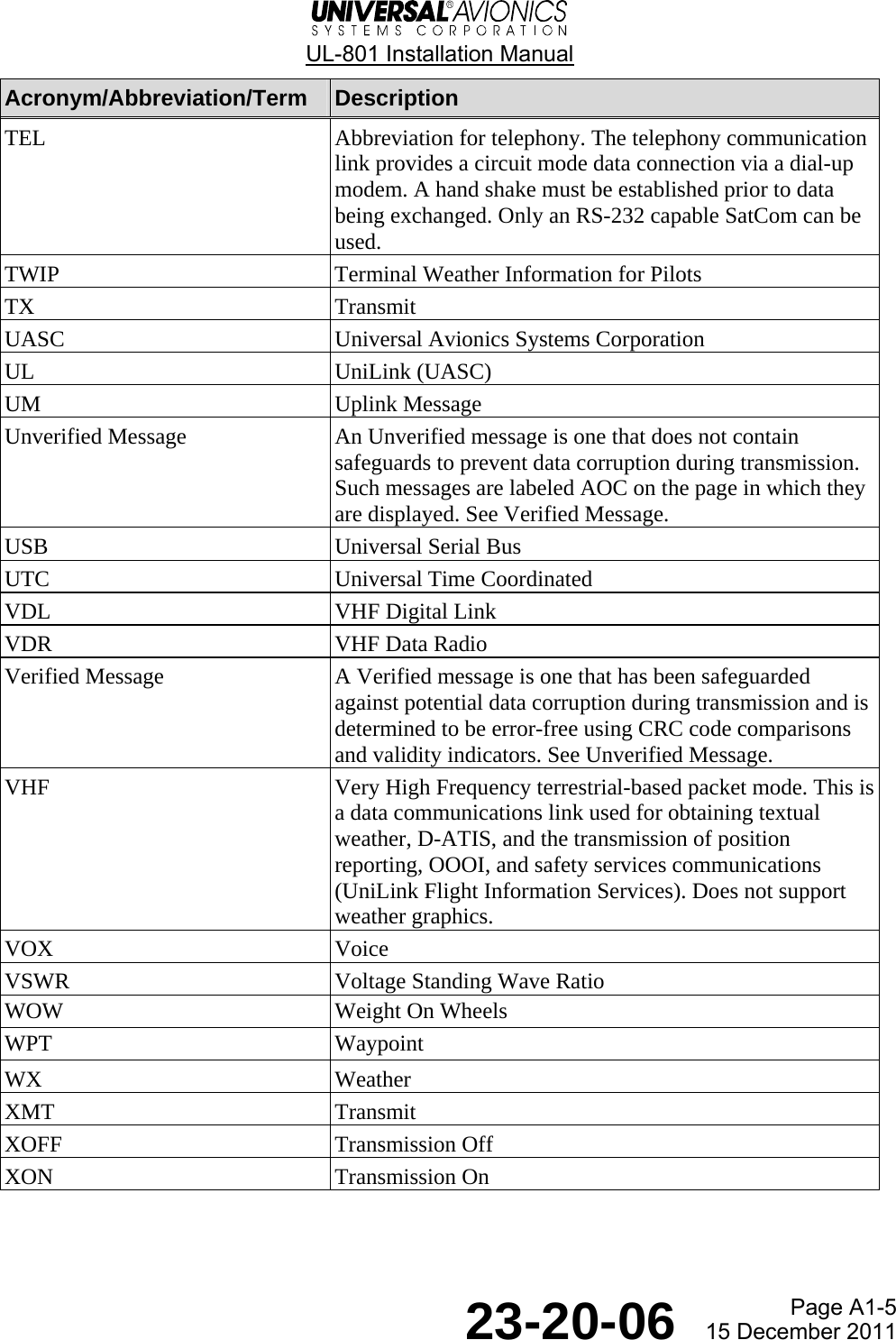
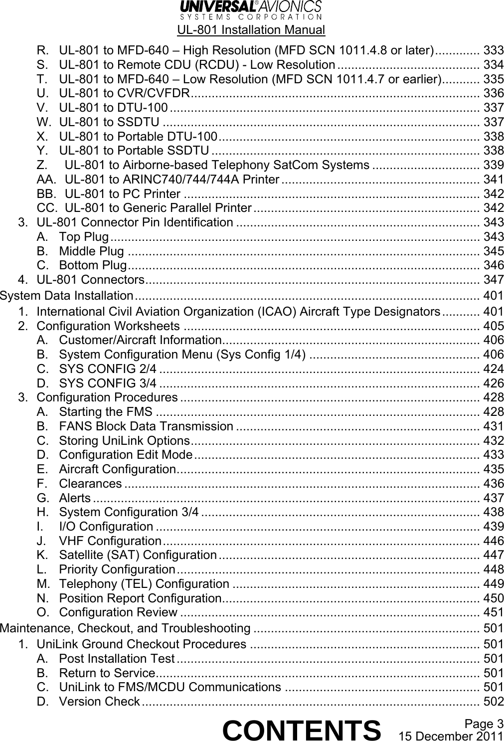
![UL-801 Installation Manual Page 429 23-20-06 15 December 2011 3. INIT 1/1 menu. a. LSK [1L] field is highlighted. Enter the local airport identifier. b. Press ENTER. 4. Local Airport Identifier window. a. Press the ACCEPT LSK [5L]. b. The INIT 1/1 menu displays. c. Press the ACCEPT LSK [5L]. d. Press the DATA key. 5. DATA 1/4 menu. a. Press the UNILINK LSK [3R]. POS INIT 1/1  dateinitial pos 23-AUG-11id ------ utcN 40 51.01 14:49:45W 074 03.65nav database expires26-AUG-11¬ACCEPT fmc ver 1000.5POS KTUS 1/ 1 tucson intlNAV N 32 06.97ARPT W 110 56.46elev 2643mag var E 12.0¬ACCEPT DATA 1/4¬NAV DATA¬PILOT DATA UNILINK®¬DISK MAINT®](https://usermanual.wiki/Universal-Avionics-Systems/10801.Users-Manual-6/User-Guide-1641691-Page-153.png)
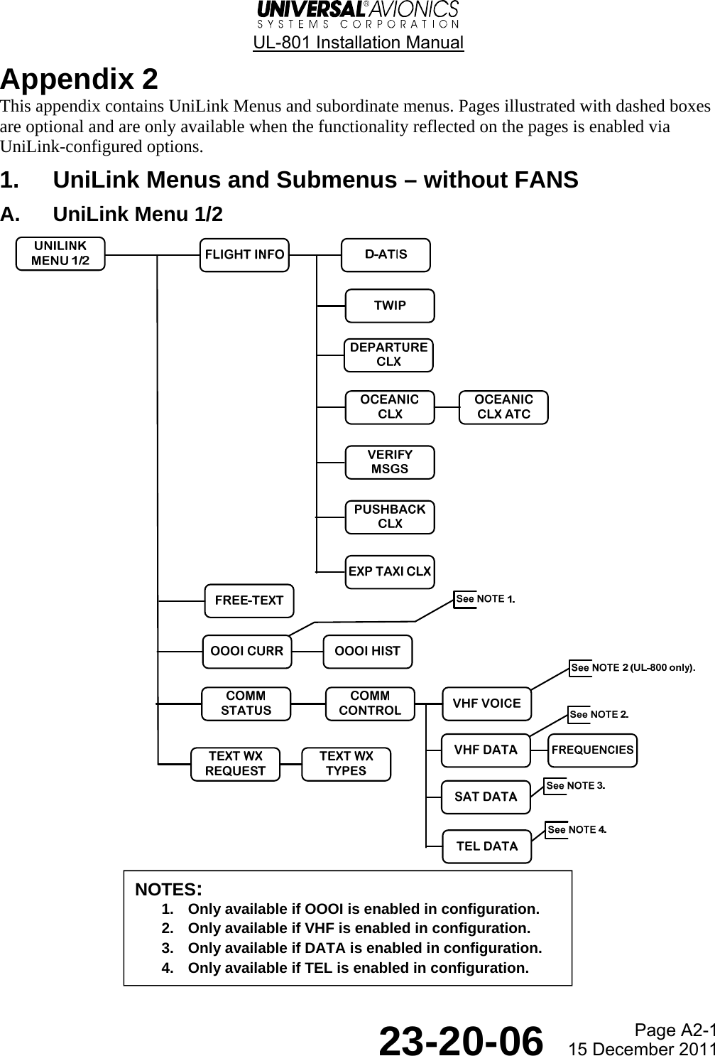
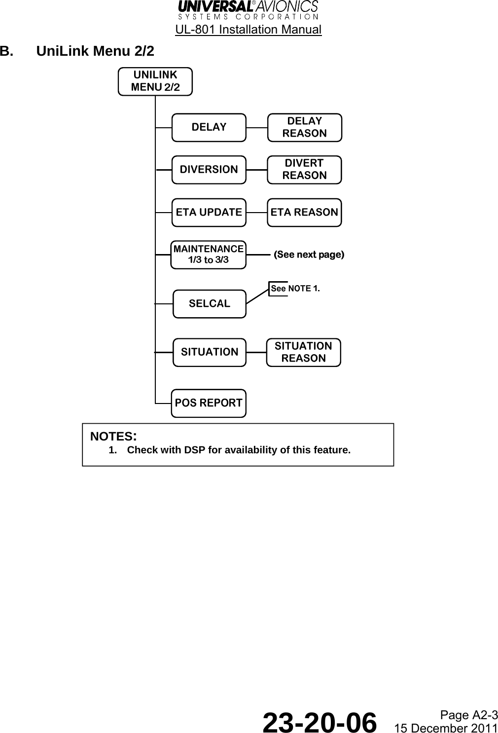
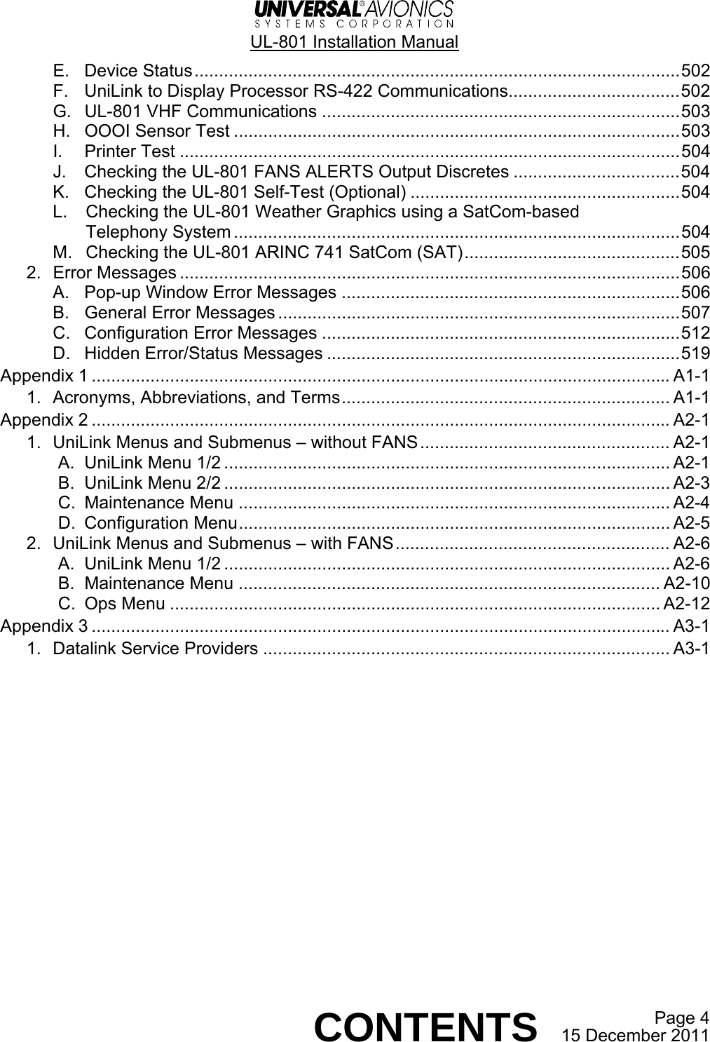
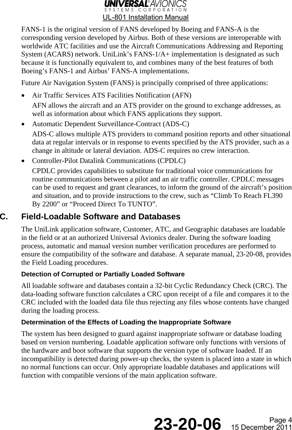
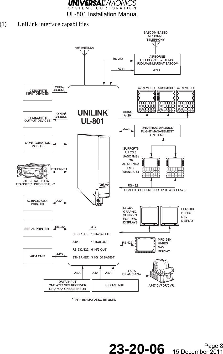
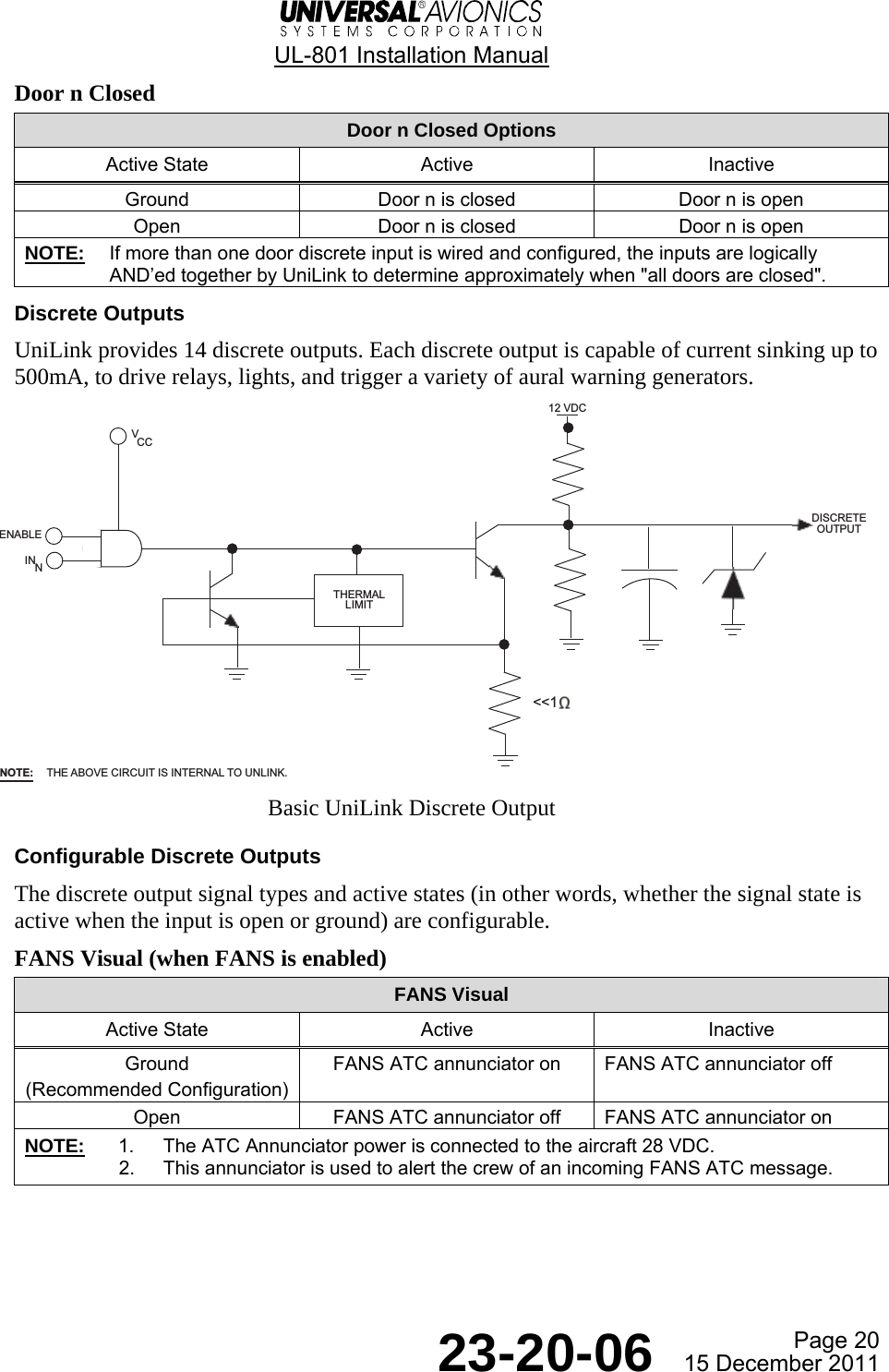
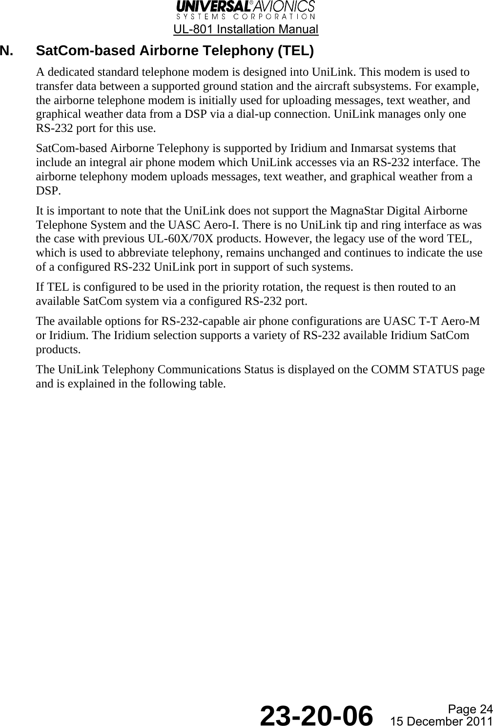
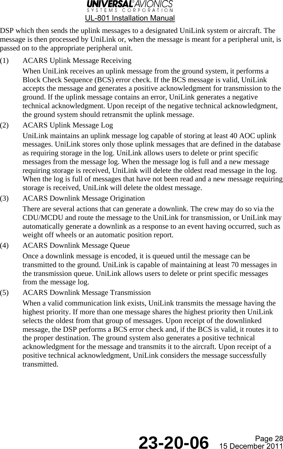
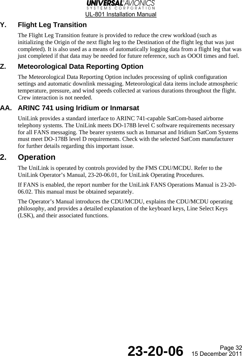
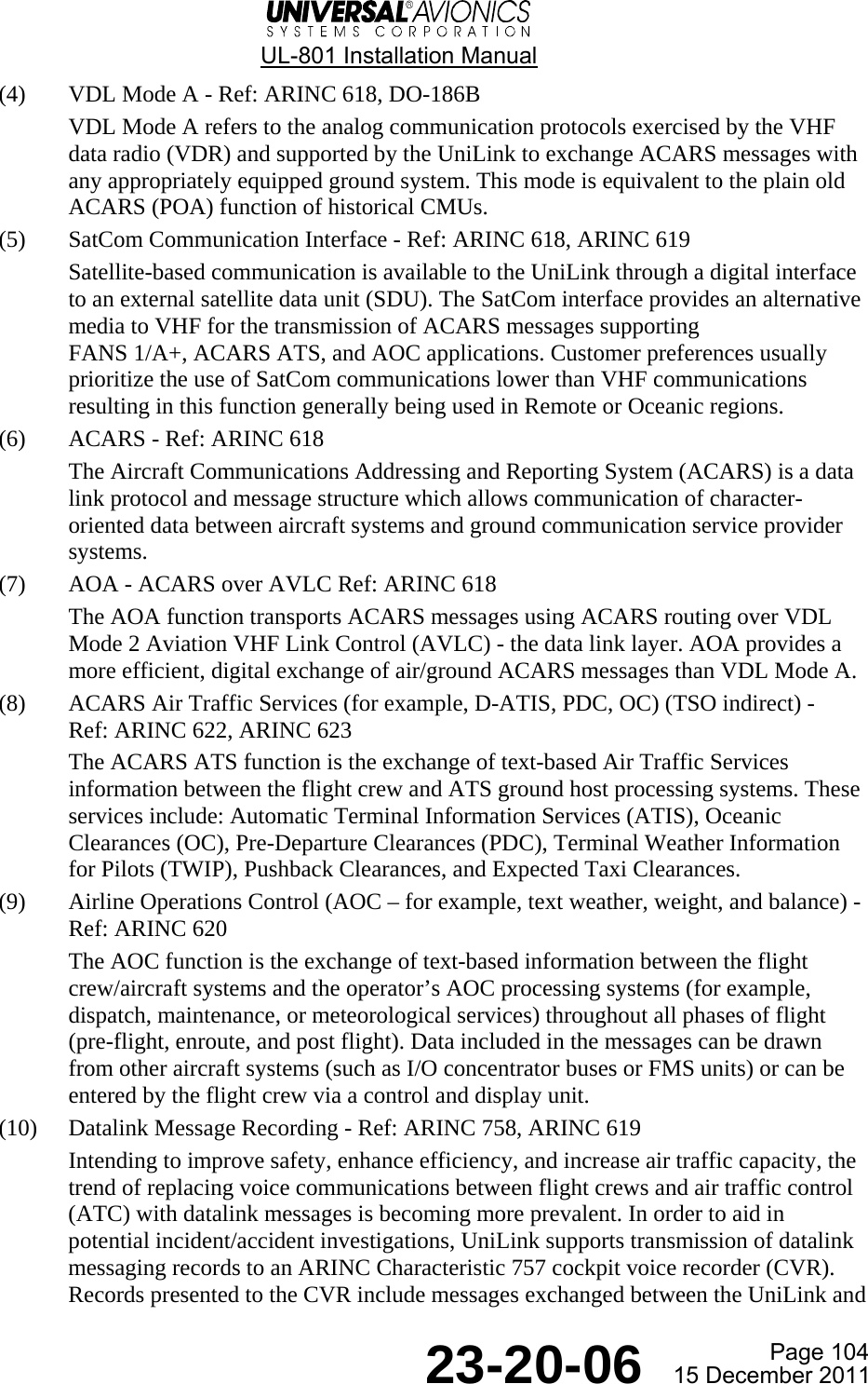
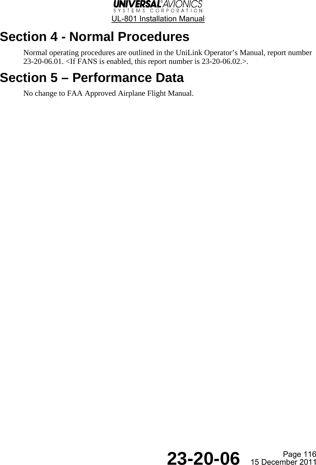
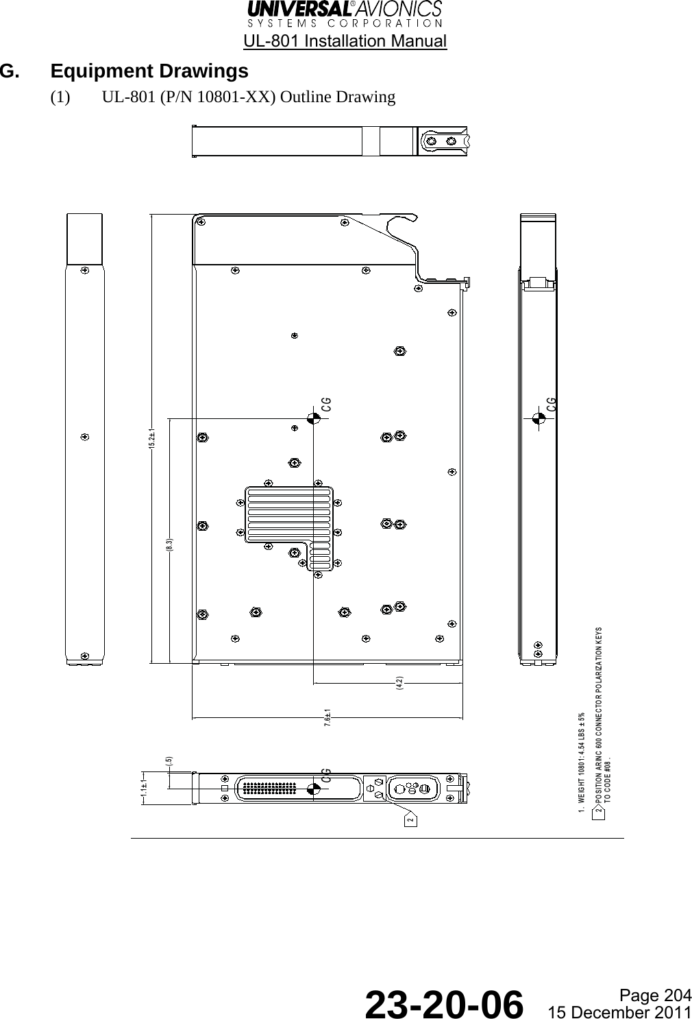
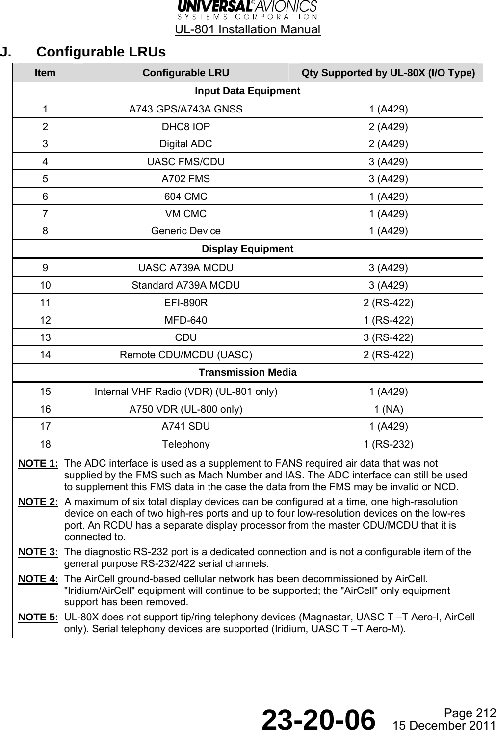
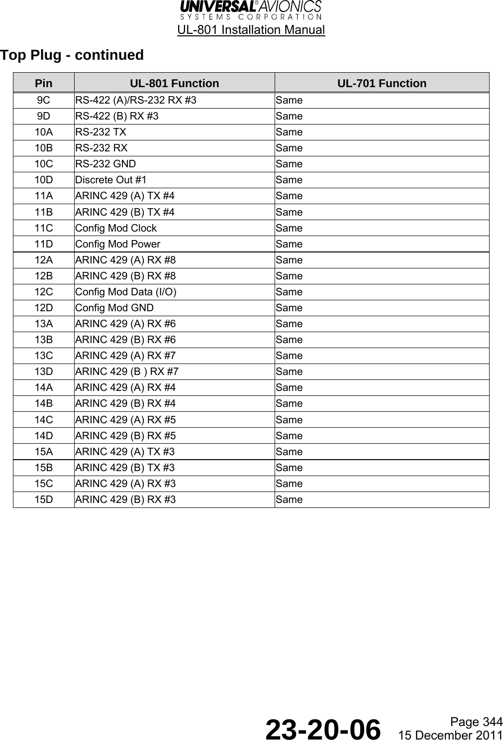
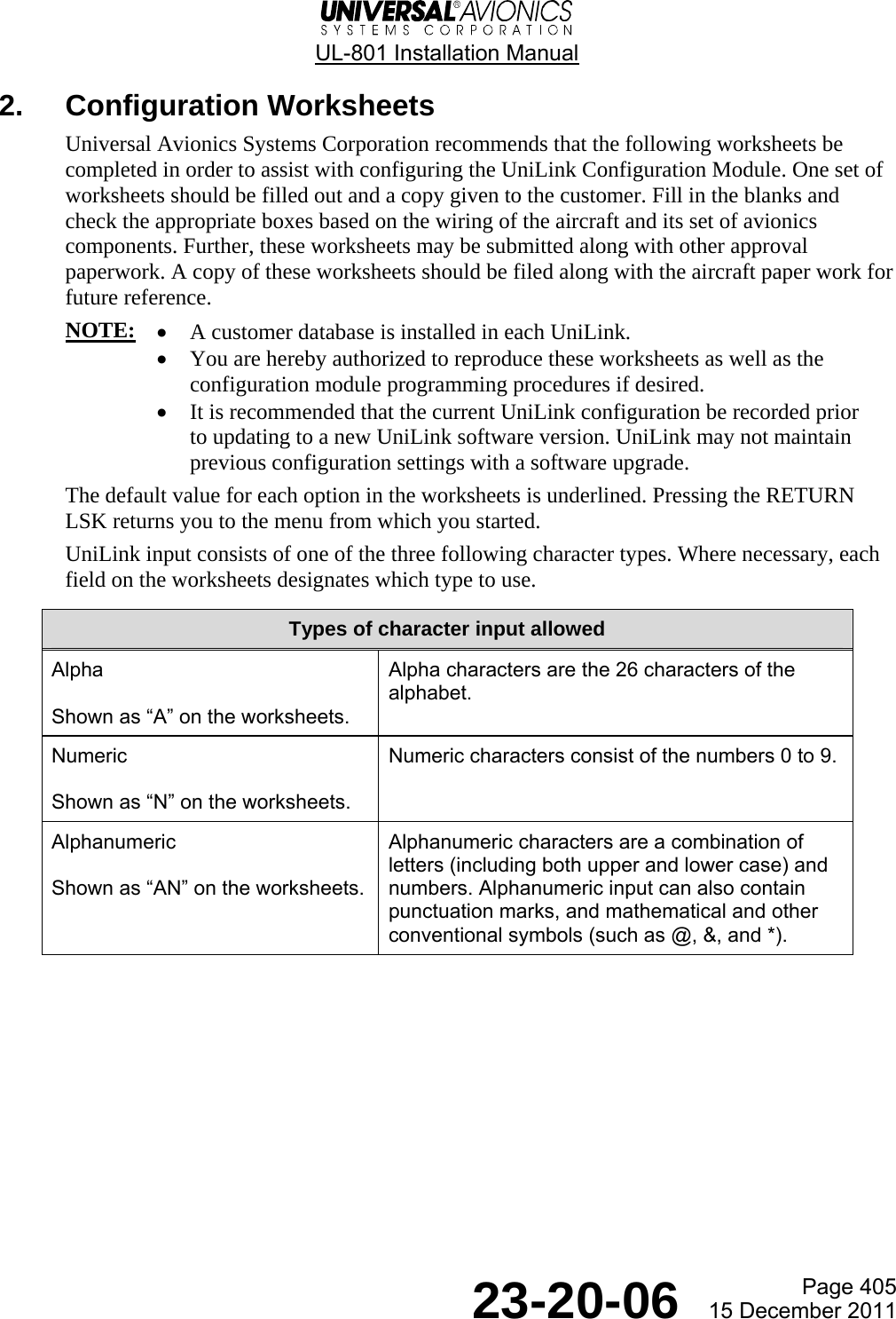
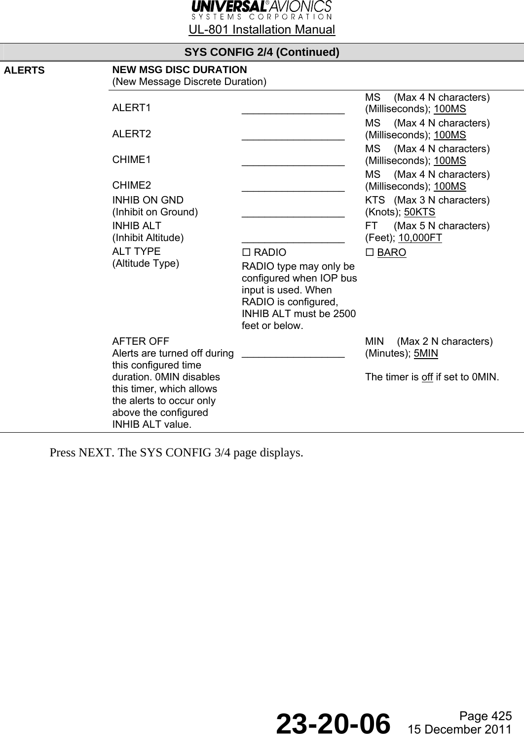
![UL-801 Installation Manual Page 430 23-20-06 15 December 2011 6. UNILINK menu. FANS-Enabled FANS-Disabled • If FANS is enabled, the top menu line displays UNILINK MENU. After the UniLink is configured, a different set of configuration options may be displayed than in the FANS-Disabled menu. • If FANS is disabled, the top menu line displays UNILINK MENU 1/2. Press the NEXT key to access UNILINK MENU 2/2. • Additional options may appear at LSK [1L], LSK [3L], LSK [2R], and LSK [3R] depending which choices were made during configuration. FANS-Enabled FANS-Disabled NOTE: The NOCOMM option may display at LSK [5R] for either a FANS-enabled or FANS-disabled UniLink. This option also displays as SAT NOCOMM, TEL NOCOMM, or VHF NOCOMM, depending on which communications link UniLink has lost. 7. UNILINK 2/2 menu for FANS-Disabled. FANS-Disabled 8. Press the MAINTENANCE LSK [4L] on either the FANS-enabled or FANS-disabled menu. UNILINK MENU¬FLIGHT INFO OPS®¬ATC¬COMM STATUS flight no.¬MAINTENANCE ---- ¡¢z¬NOCOMM RETURN® UNILINK MENU 1/2 TEXT WX®¬FREE-TEXT¬COMM STATUS MSG LOGS® ¡¢z RETURN® UNILINK MENU 2/2¬DELAY¬DIVERSION SITUATION®¬ETA UPDATE POS REPORT®¬MAINTENANCE ¡¢z RETURN®](https://usermanual.wiki/Universal-Avionics-Systems/10801.Users-Manual-6/User-Guide-1641691-Page-154.png)
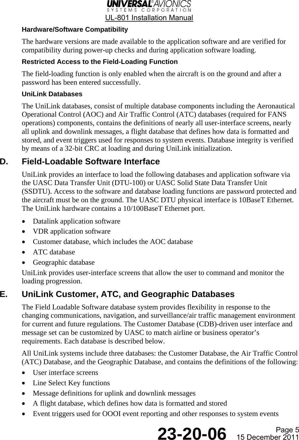
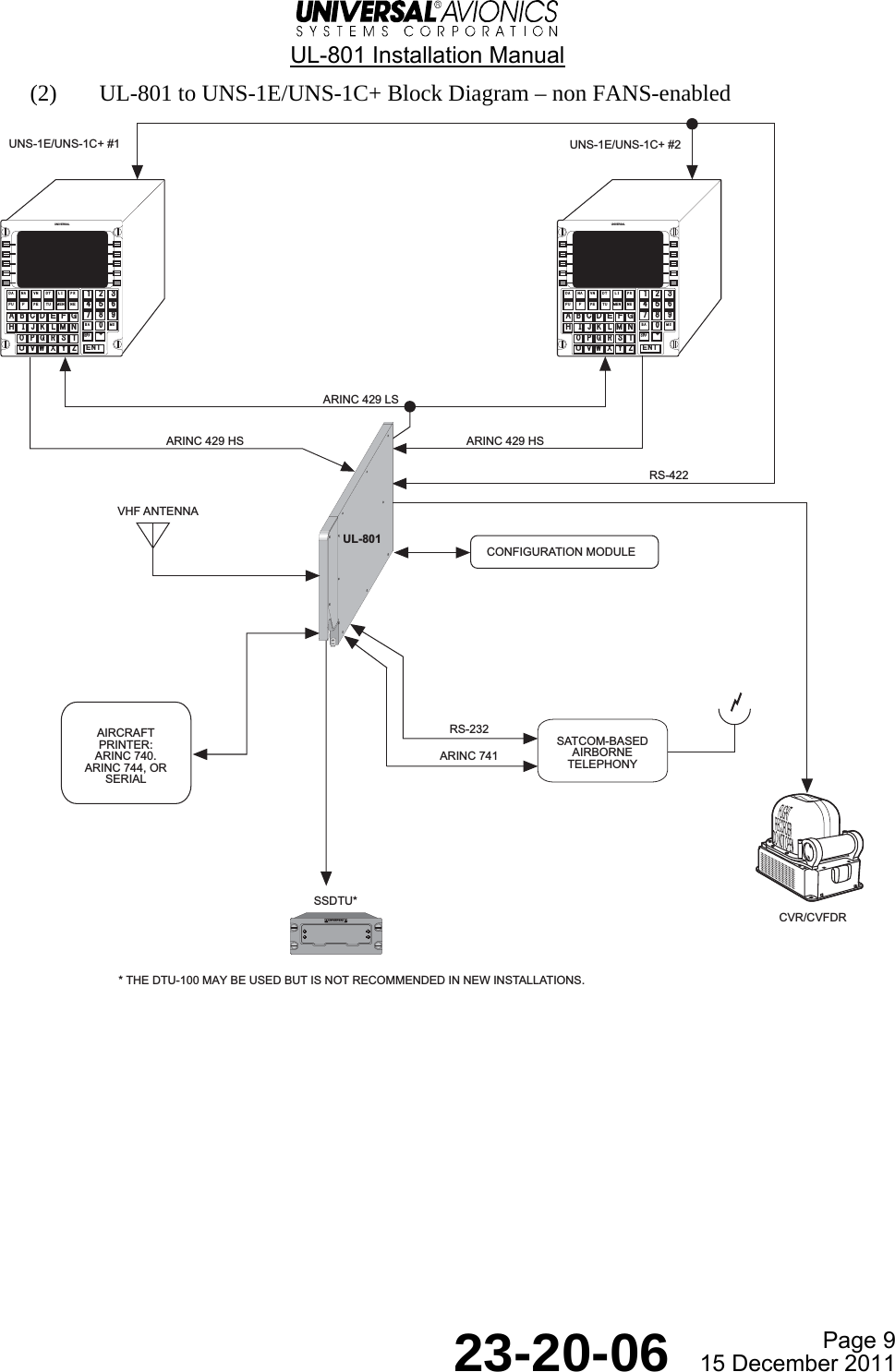
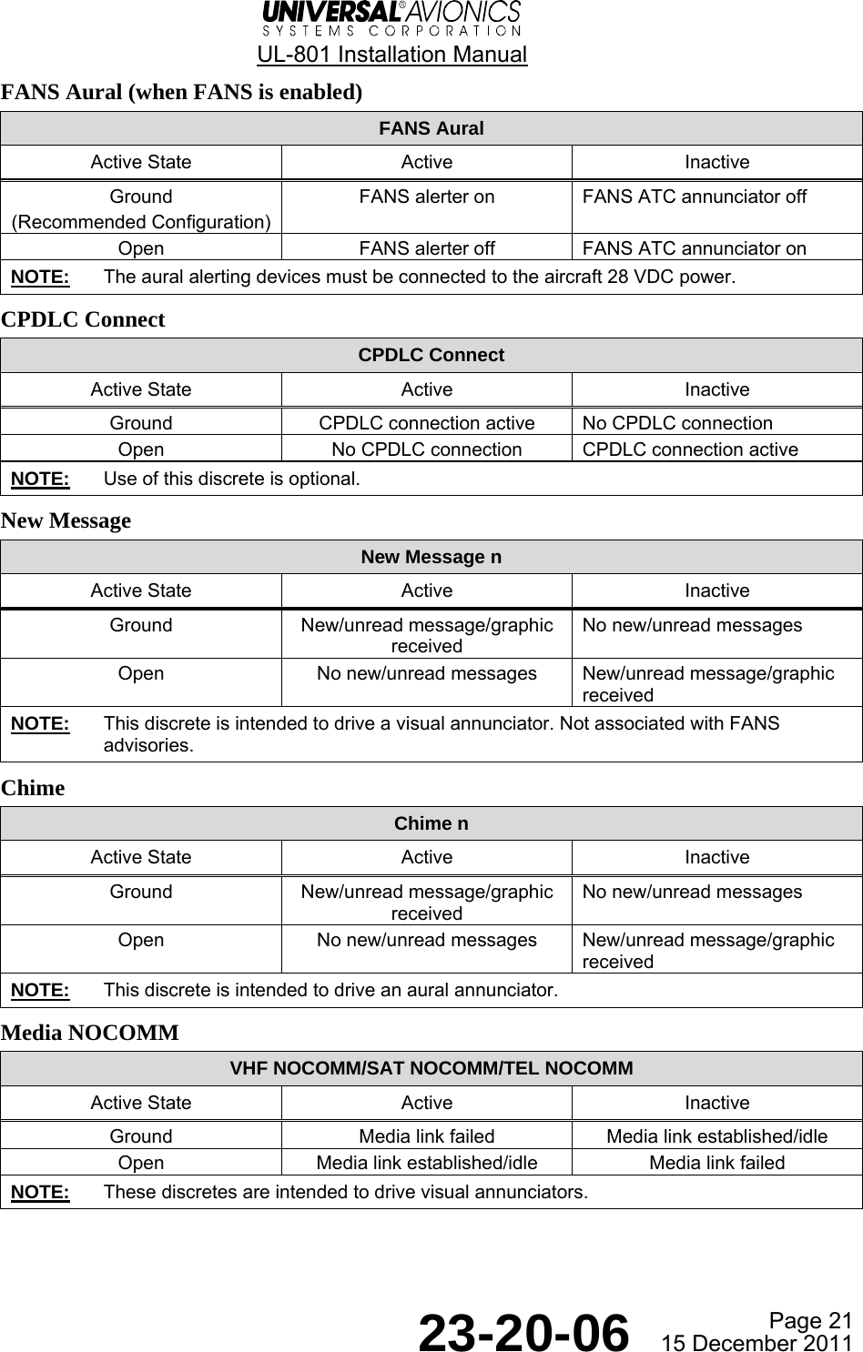
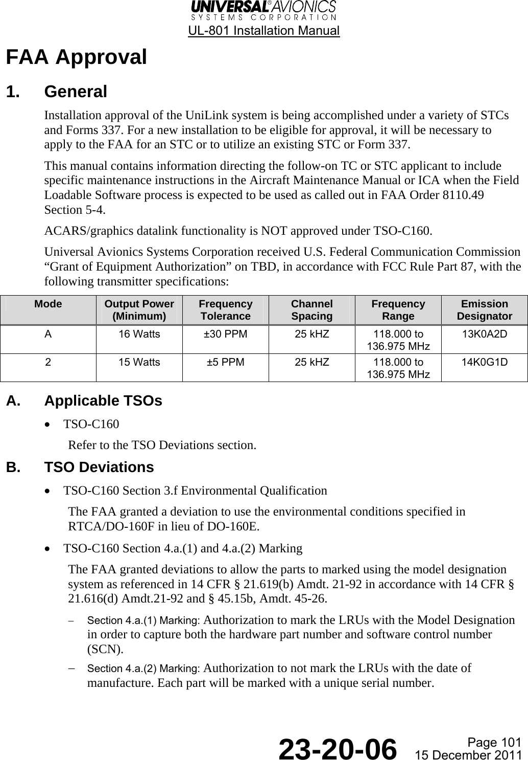
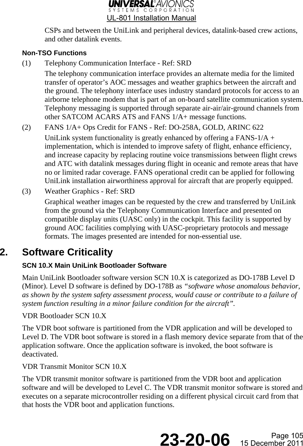
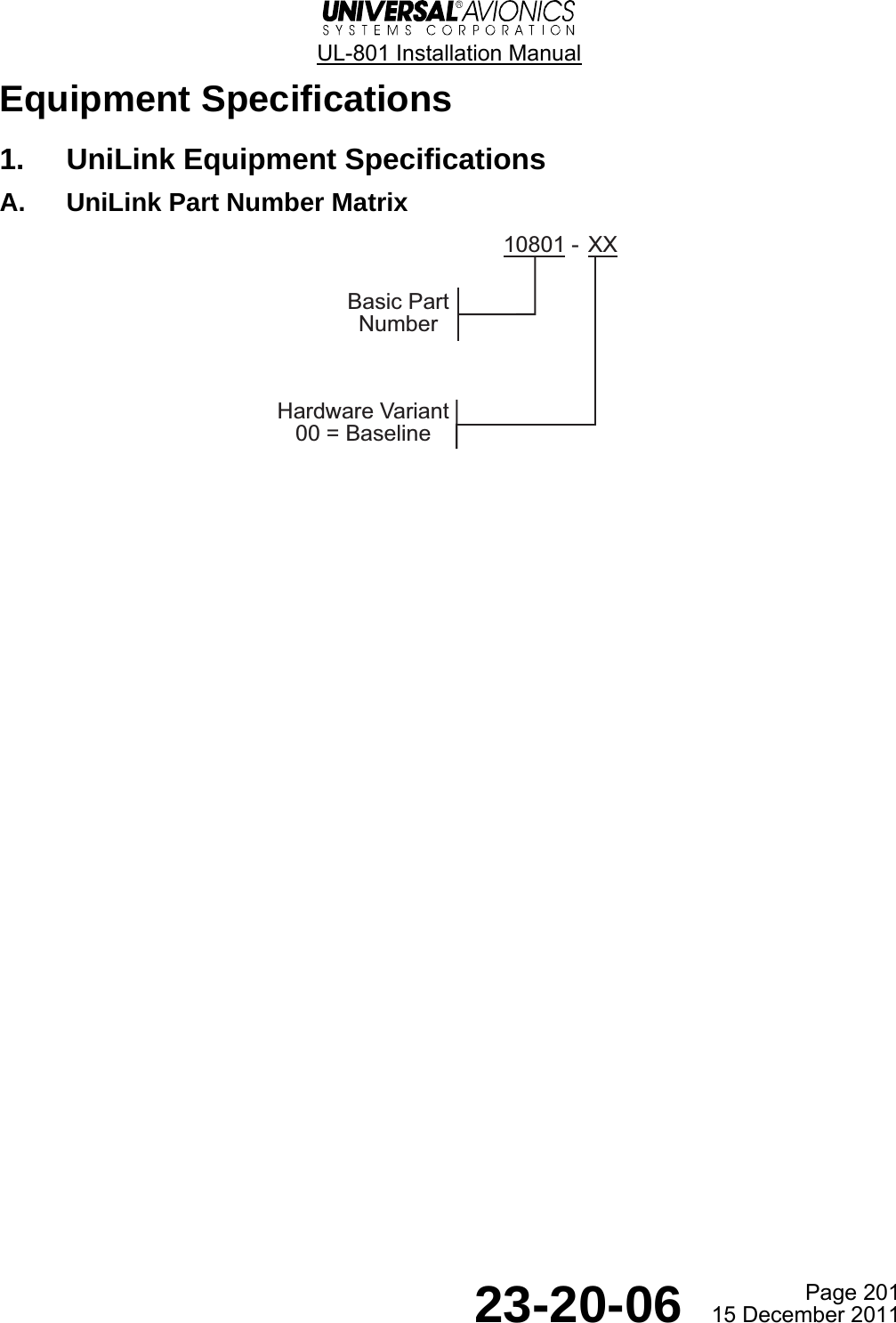
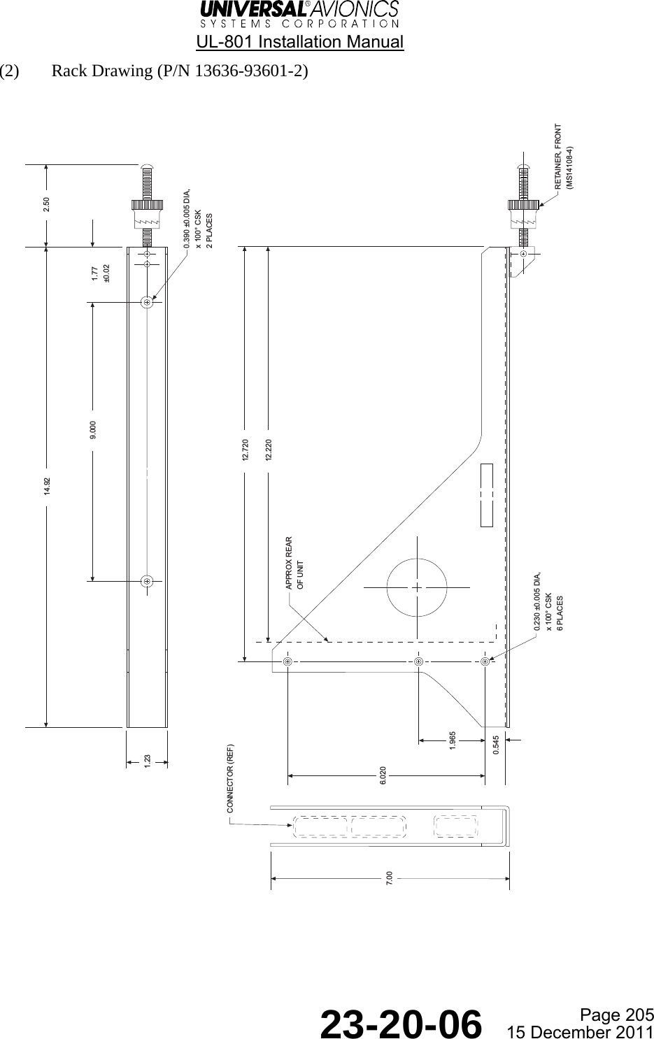
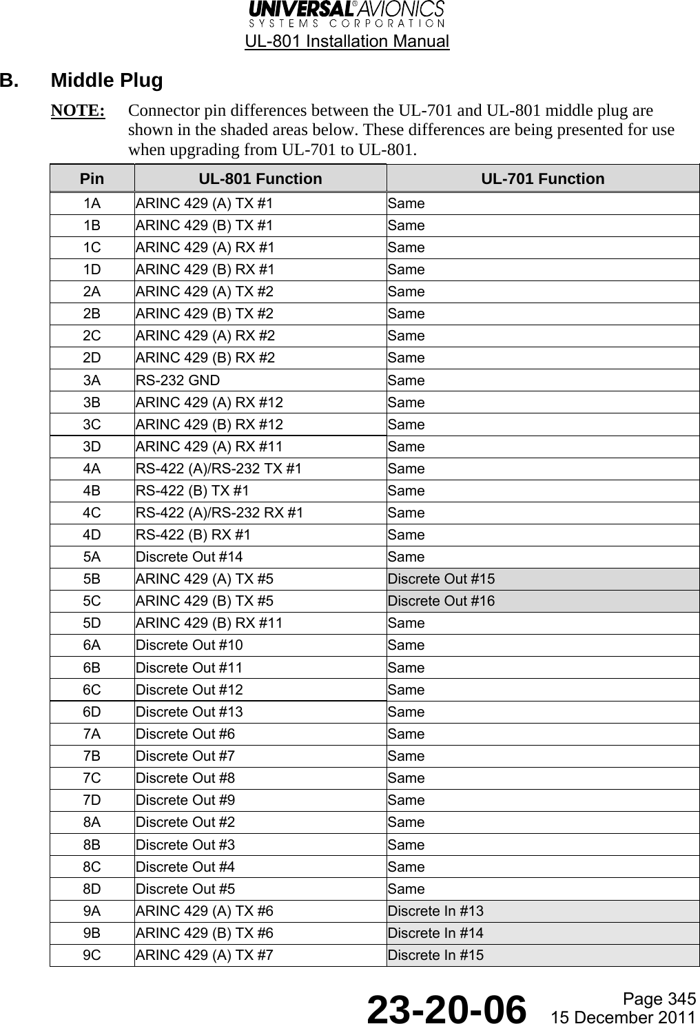
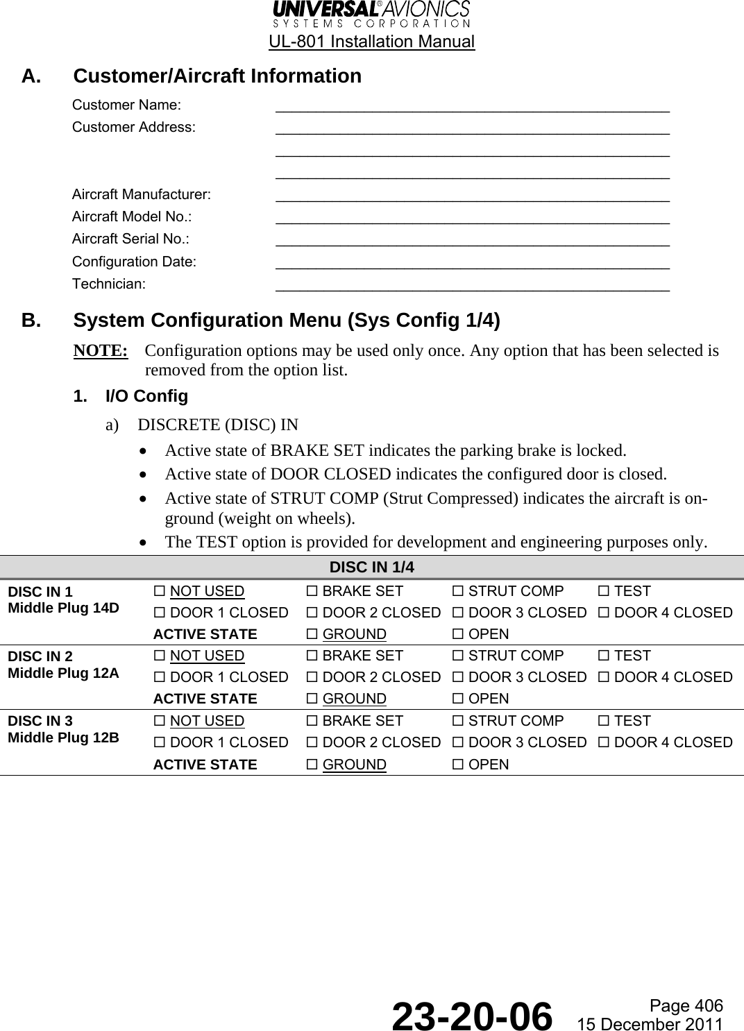
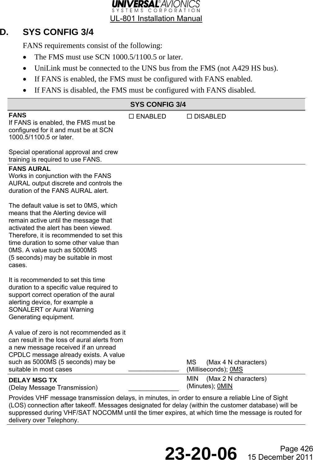
![UL-801 Installation Manual Page 431 23-20-06 15 December 2011 Use the completed worksheets, found in the Configuration Worksheets section, and enter that information into UniLink. Work through all the UniLink menus and make any necessary modifications for the configuration. The steps should be performed in the order indicated by the large number in the corner of the text box. Some of the items configured are limited to a small number of options that are selectable by pressing a line select key (LSK). The options appear one at a time in a set sequence and are included in the text of the step. Other items that may be configured are limited to more than a few options. These items are selected by typing the number of the option as presented in a numbered list. For those items that have many possible configurations, make an entry in a fill-in field. For example, the ICAO has assigned hundreds of aircraft type designators. These type designators consist of not more than four characters. On the Aircraft Configuration page the aircraft type field allows entry of up to four characters. If an entry field is not highlighted, press the corresponding line select key to move the cursor highlight to the field. B. FANS Block Data Transmission FMS SCN 1000.5/1100.5 or later is capable of transmitting FANS-specific data to support the UniLink FANS functions. In order to enable the transmission of the FMS FANS-specific data, ensure the FMS is configured to transmit over the UNS HS429-1 Bus. 1. Press the DATA key to display the DATA 1/4 page. 2. Press the PREV key to display the DATA 4/4 page. 3. Press DATE to highlight the date. 4. Enter 456789 and then press the ENTER key. The date will revert to the actual initialized date. 5. Press the NEXT key to display the DATA 1/4 page. 6. Press MAINT to display the MAINT 1/1 page. 7. Press CONFIG to display the CONFIG 1/2 page. The EDIT prompt at LSK [1R] is not normally displayed, but is displayed now because the configuration has been unlocked by entering the code on the DATA 4/4 page. 8. Press EDIT to replace EDIT with STORE and allow FMS configuration settings to be changed. 9. Press FMS CONFIG. Access the FMS CONFIG 2/4 page. 10. Press CMU. Enable FANS block data transmission. 11. Press STORE twice to restart the FMS.](https://usermanual.wiki/Universal-Avionics-Systems/10801.Users-Manual-6/User-Guide-1641691-Page-155.png)
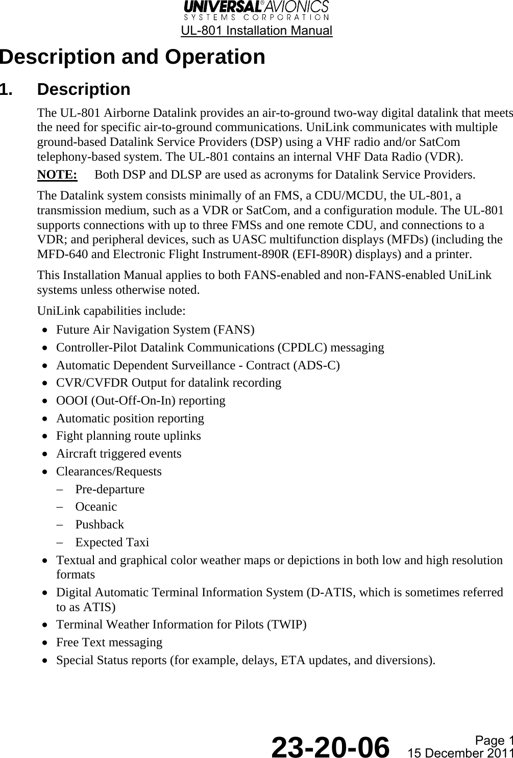
![UL-801 Installation Manual Page 432 23-20-06 15 December 2011 C. Storing UniLink Options When all new or modified UniLink options have been entered, the installer can review the configuration by pressing the REVIEW LSK [4R] on the UniLink SYS CONFIG 1/4 page. This provides easy access to review and confirm any configuration warning from the UniLink. If all modifications are acceptable, press the STORE LSK [1R]. Wait a few seconds and press the STORE LSK again. This stores the entered information, and verifies that required dependencies and consistency exist between the Configuration Data and the software, and also among the Configuration Data items. UniLink will initialize and the FMS will display the following message: UNILINK, LSK [5L], displays in small capitals. Once the UniLink has rebooted and is ready to process additional information, the word UNILINK redisplays in large capital letters. Pressing the UNILINK LSK [5L] returns the FMS to the UNILINK MENU. UNILINK/FMS COMM ERROR RESELECT UNILINK¬UNILINK](https://usermanual.wiki/Universal-Avionics-Systems/10801.Users-Manual-6/User-Guide-1641691-Page-156.png)
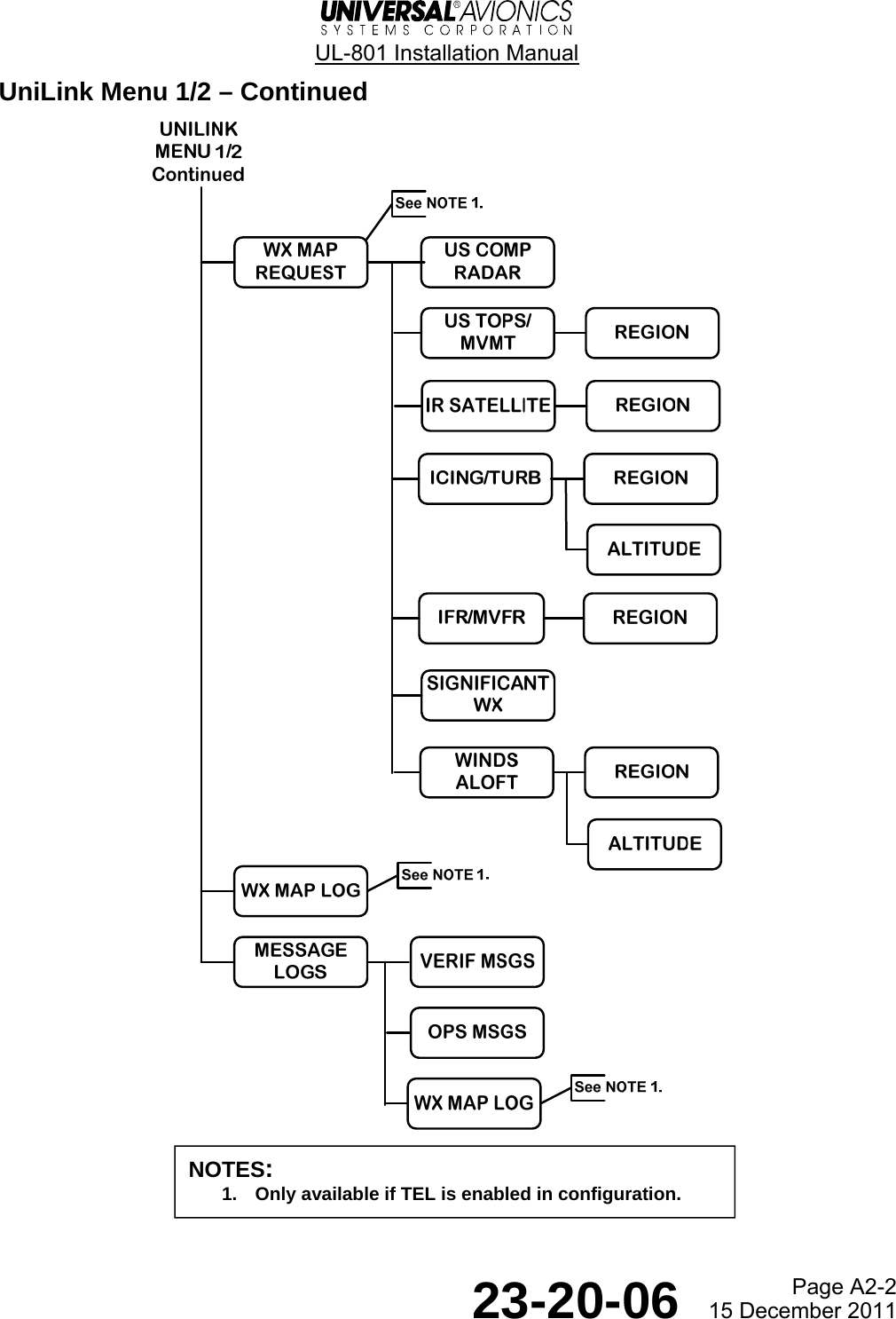
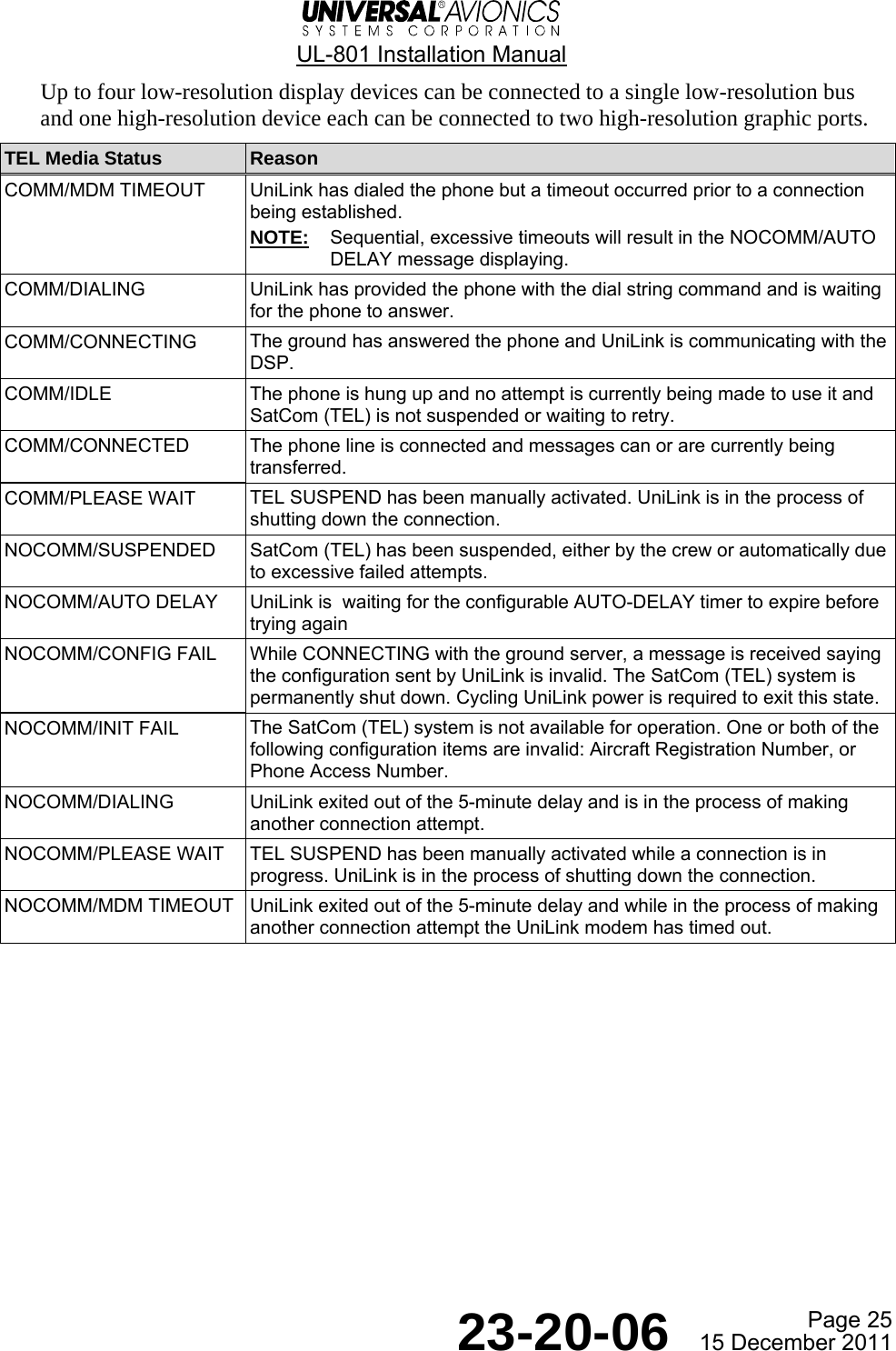
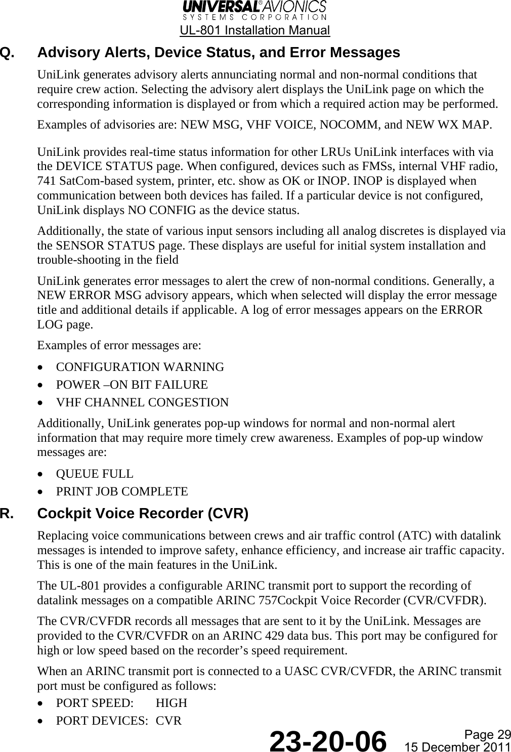
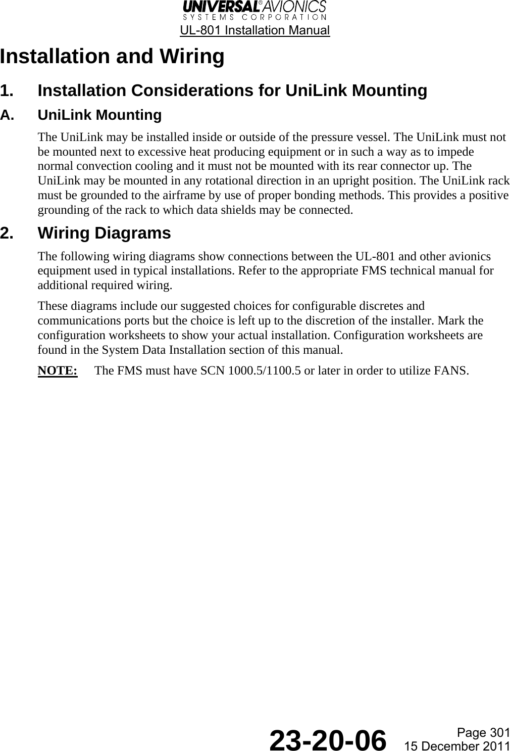
![UL-801 Installation Manual Page 433 23-20-06 15 December 2011 D. Configuration Edit Mode The Configuration Worksheets, found in the Configuration Worksheet section, should have been completed. These worksheets contain the options needed to configure UniLink. Have these worksheets available when implementing the following procedures. (1) Selecting the UniLink Display Page 1On the FMS, press [DATA]to display the DATA 1/4 page.2Press UNILINK [3R]to display the UNILINKMENU page. DATA 1/4¬NAV DATA¬PILOT DATA UNILINK®¬DISK MAINT®MAINTENANCE 1/3¬DEVICE STATUS CONFIG®¬SENSOR STATUS TESTS®¬VERSIONS POWER LOG®¬ERROR LOG --:--z¬UNILINK MENU RETURN®4Press CONFIG [1R] todisplay the SYS CONFIG1/4 page. UNILINK MENU¬FLIGHT INFO OPS®¬ATC¬COMM STATUS flight no.¬MAINTENANCE ---- ¡¢z¬NOCOMM RETURN®3Press MAINTENANCE [4L]to display theMAINTENANCE 1/3 page.](https://usermanual.wiki/Universal-Avionics-Systems/10801.Users-Manual-6/User-Guide-1641691-Page-157.png)
![UL-801 Installation Manual Page 434 23-20-06 15 December 2011 (2) Edit/Store Mode SYS CONFIG 1/4¬I/O CONFIG EDIT®¬VHF CONFIG TELEPHONE®¬SAT CONFIG POS REPORT®¬PRIORITY REVIEW® --:--z¬UNILINK MENU RETURN®NOTE: The FMS must be in an OnGround condition while youconfigure the UniLink. The dataentry field at [1R] will not beaccessible if the UniLink detectsa Weight Off Wheels condition. SYS CONFIG 1/4¬I/O CONFIG -----®¬VHF CONFIG TEL CONFIG®¬SAT CONFIG POS REPORT®¬PRIORITY REVIEW® --:--z¬UNILINK MENU RETURN®2Push EDIT [1R]. The word EDIT isreplaced with the word STORE. Do notpush STORE [1R] again until theconfiguration is complete.NOTE: Even though the LSK displaysSTORE, EDIT mode is active.1Push LSK [1R] to highlightthe data entry field. Type inthe password 456789 and pushENTER. The password will bereplaced with the word EDITand EDIT mode is enabled.](https://usermanual.wiki/Universal-Avionics-Systems/10801.Users-Manual-6/User-Guide-1641691-Page-158.png)
![UL-801 Installation Manual Page 435 23-20-06 15 December 2011 E. Aircraft Configuration SYS CONFIG 2/4media advisenabled STORE®met datadisabled AIRCRAFT®flight no.disabled CLEARANCES®oooi datadisabled ALERTS® --:--z¬UNILINK MENU1Press the NEXT key on theFMS to display the SYSCONFIG 2/4 page.3Press AIRCRAFT [2R]to display theAIRCRAFT page.2Press LSK [1L] thru [4L]and select the ENABLEDor DISABLED option foreach item. AIRCRAFTtype---- STORE®registration icao addr------- --------ºairline id--/---fin number--- --:--z5Repeat Step 4 on LSKs[2L], [3L], and [4L]respectively forREGISTRATION, AIRLINE ID,and FIN NUMBER. Press[2R] to highlight theICAO ADDR field. Enterthe ICAO ADDR and pressENTER.6Press RETURN [5R] to returnto the SYSTEM CONFIG 2/4page.4Press [1L] to highlightthe TYPE data entryfield. Enter the Typeand press ENTER.](https://usermanual.wiki/Universal-Avionics-Systems/10801.Users-Manual-6/User-Guide-1641691-Page-159.png)
![UL-801 Installation Manual Page 436 23-20-06 15 December 2011 F. Clearances 1Press CLEARANCES [3R]to display theCLEARANCES page. SYS CONFIG 2/4media advisenabled STORE®met datadisabled AIRCRAFT®flight nodisabled CLEARANCES®oooi datadisabled ALERTS® --:--z¬UNILINK MENU2Press LSK [2L] andselect the ENABLED orDISABLED option foreach item. Repeat forLSK [3L].3Press LSK [2R] andselect the ENABLEDor DISABLED optionfor each item.Repeat for LSK [3R]. CLEARANCES STORE®oceanic departuredisabled disabledpushback exp taxidisabled disabled --:--z¬UNILINK MENU RETURN®4Press RETURN [5R] to returnto the SYS CONFIG 2/4 page.](https://usermanual.wiki/Universal-Avionics-Systems/10801.Users-Manual-6/User-Guide-1641691-Page-160.png)
![UL-801 Installation Manual Page 437 23-20-06 15 December 2011 G. Alerts SYS CONFIG 2/4media advisenabled STORE®met datadisabled AIRCRAFT®flight nodisabled CLEARANCES®oooi timesdisabled ALERTS® --:--z¬UNILINK MENUPush ALERTS [4R] todisplay the ALERTS page.1Push RETURN [5R] to returnto the SYS CONFIG 2/4 page.4ALERTSnew msg discduration: STORE®alert¡ alert inhib alt¡ººms ¡ººms {¡ººººftchime¡ chime alt type¡ººms ¡ººms baroinhib on gnd after off}ºkts min --:--z RETURN®2Push LSK [2L] to highlightthe data entry field.Enter a value for ALERT1.Push ENTER to move thecursor to the ALERT2 field.Continuing to push the ENTERkey moves the cursor to theCHIME1, CHIME2, INHIB ON GND,INHIB ALT, and AFTER OFFfields. Values may be enteredin these fields or left as thedefault if no value isentered.3A value for ALT TYPE canonly be entered by pushingLSK [4R] and then enteringa value.](https://usermanual.wiki/Universal-Avionics-Systems/10801.Users-Manual-6/User-Guide-1641691-Page-161.png)
![UL-801 Installation Manual Page 438 23-20-06 15 December 2011 H. System Configuration 3/4 1Push NEXT on the FMSkeypad to display theSYS CONFIG 3/4 page. SYS CONFIG 3/4fansenabled STORE®fans aural fans latencyºms ºsecdelay msg tx supp addrºmin -------ground delayºmin --:--z¬UNILINK MENU2Push LSK [1L] to toggleenabled/disabled in the FANS field.Push ENTER to move the cursor tothe FANS AURAL field. Push LSK [2L]and enter a value. Continuing topush the ENTER key moves the cursorto the DELAY MSG TX, GROUND DELAY,FANS LATENCY, and SUPP ADDR fields.Values may be entered in thesefields or left as the default ifno value is entered.NOTE: Pushing ENTER cycles throughall fields except the FANS field.LSK [1L] must be pushed in orderto enter a value in the FANS field.3Push NEXT twice to return tothe SYS CONFIG 1/4 page.](https://usermanual.wiki/Universal-Avionics-Systems/10801.Users-Manual-6/User-Guide-1641691-Page-162.png)
![UL-801 Installation Manual Page 439 23-20-06 15 December 2011 I. I/O Configuration SYS CONFIG 1/4¬I/O CONFIG STORE®¬VHF CONFIG TEL CONFIG®¬SAT CONFIG POS REPORT®¬PRIORITY REVIEW® --:--z¬UNILINK MENU1Press I/O CONFIG [1L] todisplay the I/O CONFIG page. I/O CONFIG¬DISCRETE IN SERIAL®¬DISCRETE OUT GRAPHICS®¬ARINC RECEIVE¬ARINC TRANSMIT º§z¬UNILINK MENU RETURN®](https://usermanual.wiki/Universal-Avionics-Systems/10801.Users-Manual-6/User-Guide-1641691-Page-163.png)
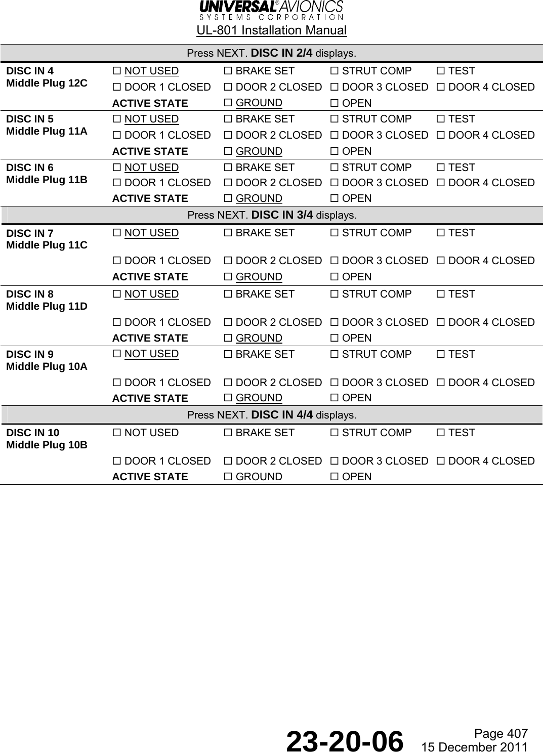
![UL-801 Installation Manual Page 440 23-20-06 15 December 2011 (1) Discrete In DISC IN 1/4 STORE®disc in ¡ active statenot used grounddisc in active statenot used grounddisc in £ active statenot used ground º§z¬UNILINK MENU RETURN®1Press DISCRETE IN [1L] todisplay the DISC IN 1/4page.5Press NEXT to display the next DISC INpage and repeat steps 2, 3 and 4until all 10 discrete inputs are set.Press RETURN [5R].2Press LSK [2L] to configureDISC IN 1. The DISC IN OPT 1/2page displays with a listof all available options.DISC IN OPT 1/2 select ¡ not used #- brake set £ strut comp ¢ test door ¡ closed § door closed ¶ door £ closed º§z¬UNILINK MENU RETURN®3Enter the number of thedesired option and pressENTER. The DISC IN 1/4page displays.4Press LSK [2R] and toggle the activestate of the DISC IN 1 betweenGROUND and OPEN. I/O CONFIG¬DISCRETE IN SERIAL®¬DISCRETE OUT GRAPHICS®¬ARINC RECEIVE¬ARINC TRANSMIT º§z¬UNILINK MENU RETURN®NOTE: Press the NEXT or PREV key totoggle between DISC IN OPT pages 1and 2.](https://usermanual.wiki/Universal-Avionics-Systems/10801.Users-Manual-6/User-Guide-1641691-Page-164.png)
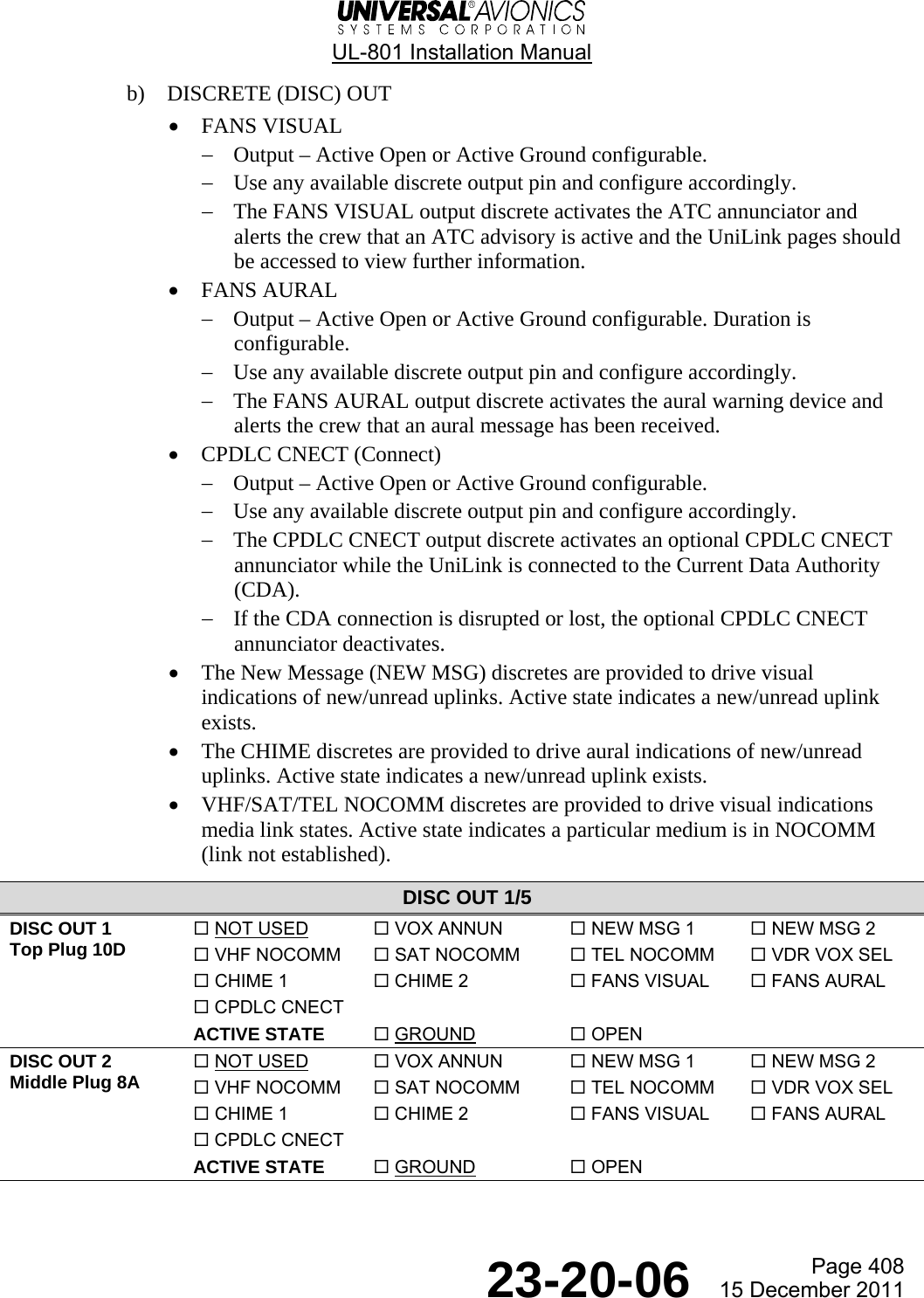
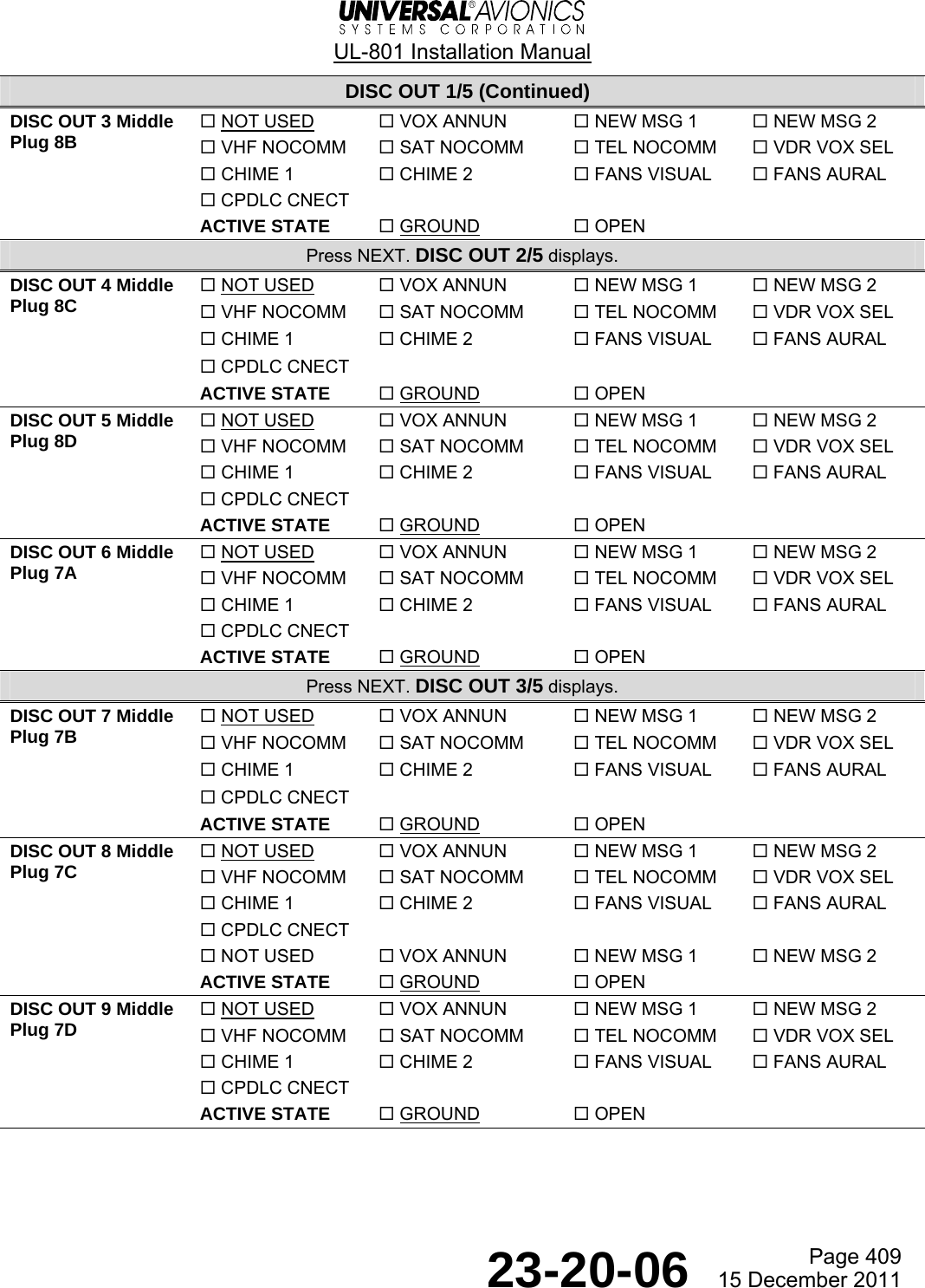
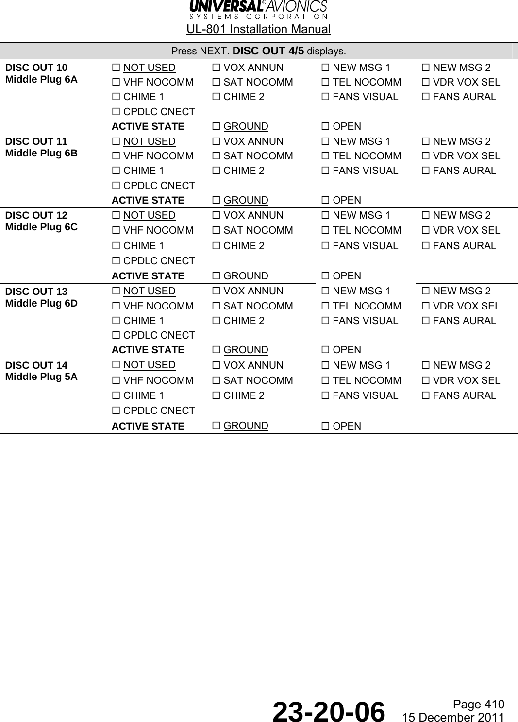
![UL-801 Installation Manual Page 441 23-20-06 15 December 2011 (2) Discrete Out DISC OUT 1/5 STORE®disc out ¡ active statenot used grounddisc out active statenot used grounddisc out £ active statenot used ground --:--z¬UNILINK MENU RETURN®1Press DISCRETE OUT[2L] to display theDISC OUT 1/5 page.5Repeat steps 2, 3, and 4 until all14 discrete outputs are set and thenpress RETURN [5R].2Press LSK [2L] to configureDISC OUT 1. The DISC OUT OPT1/2 page displays with a listof all available options.DISC OUT OPT 1/2 select ¡ not used #- vox annun £ new msg ¡ ¢ new msg vhf nocomm § sat nocomm ¶ tel nocomm --:--z¬UNILINK MENU RETURN®3Enter the number of thedesired option and pressENTER. For more options,press NEXT to display thethe DISC OUT OPT 2/2 page.4Press LSK [2R] and toggle theactive state of the DISC OUT 1between GROUND and OPEN. I/O CONFIG¬DISCRETE IN SERIAL®¬DISCRETE OUT GRAPHICS®¬ARINC RECEIVE¬ARINC TRANSMIT º§z¬UNILINK MENU RETURN®DISC OUT OPT 2/2 select ¡ vdr box sel #- chime ¡ £ chime ¢ fans visual fans aural § cpdlc cnect --:--z¬UNILINK MENU RETURN®](https://usermanual.wiki/Universal-Avionics-Systems/10801.Users-Manual-6/User-Guide-1641691-Page-165.png)
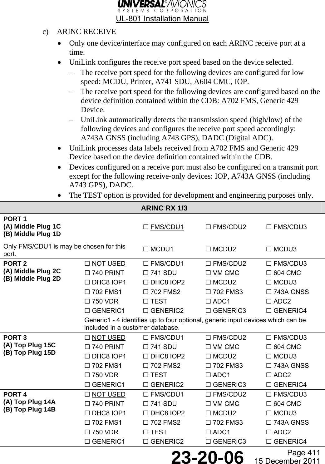
![UL-801 Installation Manual Page 442 23-20-06 15 December 2011 (3) ARINC Receive I/O CONFIG¬DISCRETE IN SERIAL®¬DISCRETE OUT GRAPHICS®¬ARINC RECEIVE¬ARINC TRANSMIT --:--z¬UNILINK MENU RETURN®1Press ARINC RECEIVE [3L]to display the ARINC RX1/3 page.5Repeat steps 2 and 3 until all16 ARINC RX ports are set andthen push RETURN [5R].3Enter the number of the desiredoption for port 1 and press ENTER.This automatically returns you tothe ARINC RX 1/3 page. Selectanother port to configure. TheARINC RX OPT 1/4 page displays.2Press LSK [2L] to configurePORT 1. The ARINC RX OPT pagedisplays with a list of theavailable options for Port 1.NOTE: Choosing Ports 2 - 16displays one of ARINC RXOPT 1/4 pages. ARINC RX 1/3 STORE®port ¡ port ¢fms/cdu¡ not usedport port ¶¢¡ sdu not usedport £ port §not used not used --:--z¬UNILINK MENU RETURN® ARINC RX OPT 1/4 select ¡ not used #- fms/cdu £ fms/cdu£ ¢ ¶¢º print ¶¢¡ sdu § vm cmc ¶ §º¢ cmc--:--z RETURN® ARINC RX OPT select ¡ fms/cdu¡ #- fms/cdu £ fms/cdu£ ¢ mcdu¡ mcdu § mcdu£ ARINC RX OPT 3/4 select ¡ ¶º fms£ #- ¶¢£a gnss £ ¶º vdr ¢ test adc¡ § adc ¶ generic¡--:--z RETURN® ARINC RX OPT 2/4 select ¡ dhc iop¡ #- dhc iop £ mcdu¡ ¢ mcdu mcdu£ § ¶º fms¡ ¶ ¶º fms--:--z RETURN®4After configuring all the portson the chosen ARINC RX OPT page,press NEXT to go to the next ARINCRX OPT page. ARINC RX OPT 4/4 select ¡ generic #- generic£ £ generic¢--:--z RETURN®](https://usermanual.wiki/Universal-Avionics-Systems/10801.Users-Manual-6/User-Guide-1641691-Page-166.png)
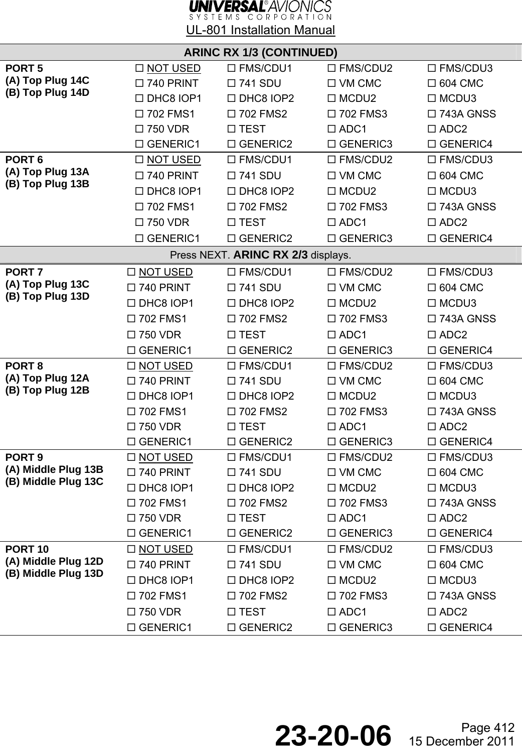
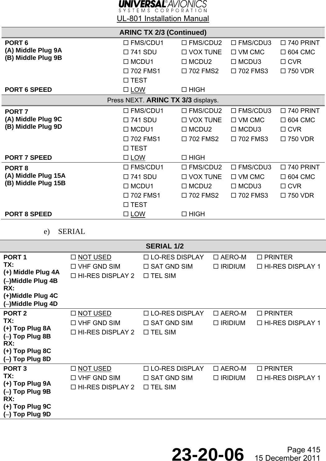
![UL-801 Installation Manual Page 443 23-20-06 15 December 2011 (4) ARINC Transmit ARINC TX 1/3 STORE®port ¡ speed deviceslow PORT 1®port speedlow PORT 2®port £ speedlow PORT 3® --:--z¬UNILINK MENU RETURN®1Press ARINC TRANSMIT [4L]to display the ARINC TX 1/3page.4Press LSK [1L] and <*>appears to indicate that theitem is selected. Press theLSK again and <*> disappears.Repeat for each device.2PORT 1 SPEED defaults to LOW.Press PORT 2 SPEED [3L] andselect the LOW or HIGHspeed option. Repeatfor the rest of the ARINCTX ports. Ports 4 - 8 areon ARINC TX pages 2 and 3. ARINC TX OPT 1/3port ¡¬FMS/CDU1<*> 741 SDU®¬FMS/CDU2 VOX TUNE®¬FMS/CDU3 VM CMC®¬740 PRINT 604 CMC®--:--z¬UNILINK MENU RETURN® I/O CONFIG¬DISCRETE IN SERIAL®¬DISCRETE OUT GRAPHICS®¬ARINC RECEIVE¬ARINC TRANSMIT --:--z¬UNILINK MENU RETURN®NOTE: Multiple port devicescan be configured ona single port but nodevice may be configuredso that it resideson more than one port.3Press PORT 1 [2R] to display theARINC TX OPT 1/3 page. A list ofdevices available for each of theARINC TX ports displays.5Press NEXT to display ARINCTX 2/3 and follow the procedurein step 4. Press NEXT again to displayARINC TX 3/3. Once all ARINC TX portsare configured, press RETURN twice toreturn to the I/O CONFIG page.](https://usermanual.wiki/Universal-Avionics-Systems/10801.Users-Manual-6/User-Guide-1641691-Page-167.png)
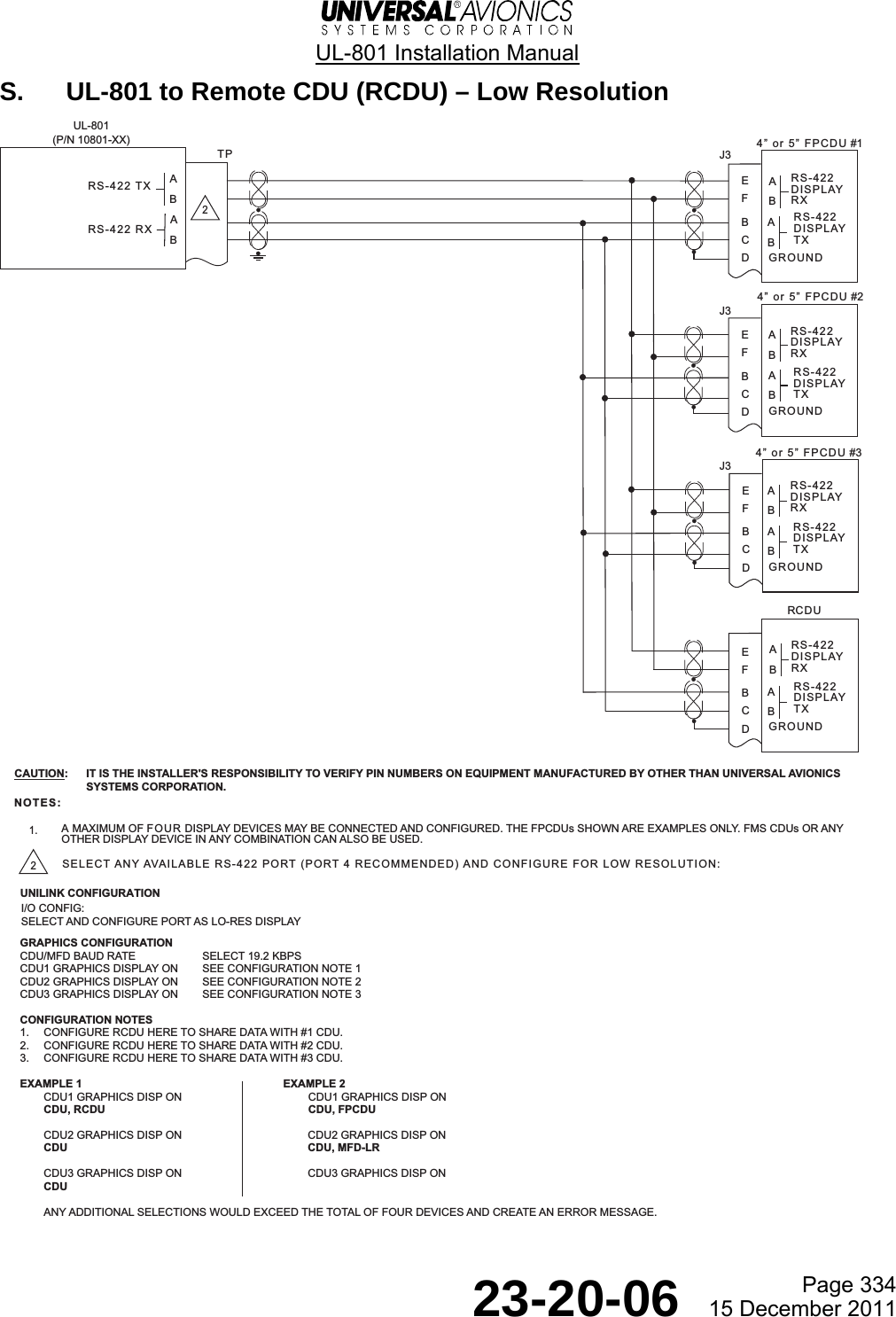
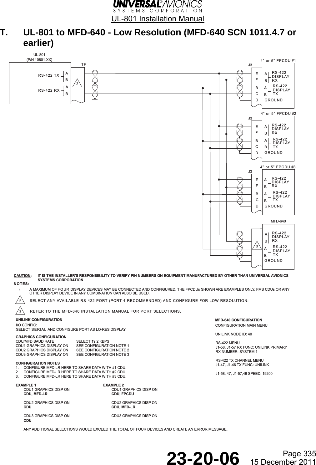
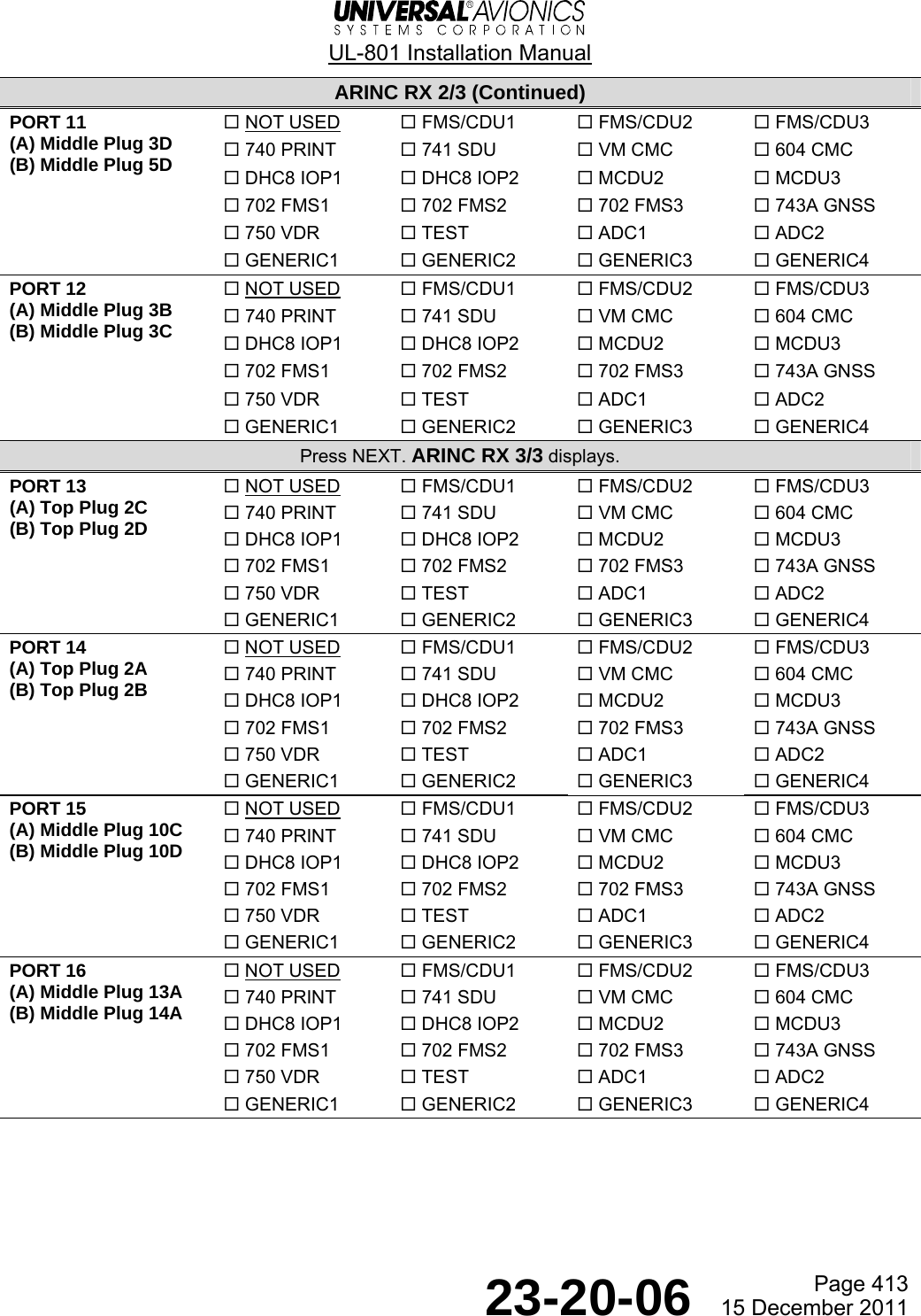
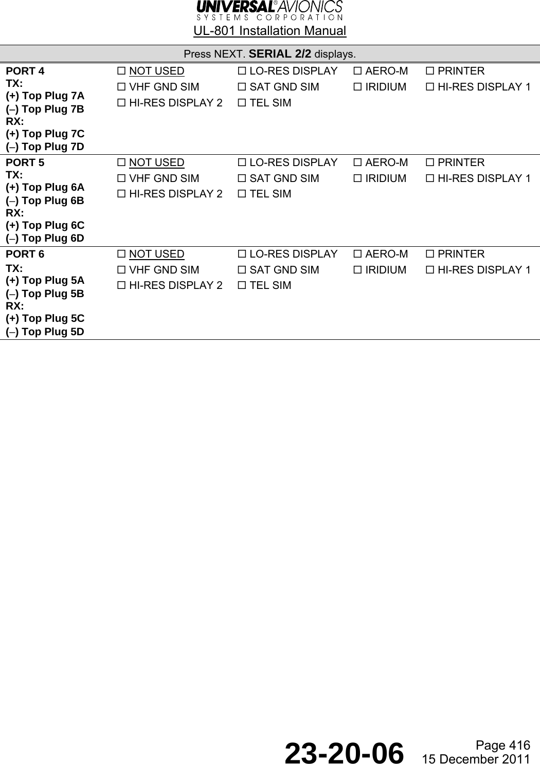
![UL-801 Installation Manual Page 444 23-20-06 15 December 2011 (5) Serial Port Configuration I/O CONFIG¬DISCRETE IN SERIAL®¬DISCRETE OUT GRAPHICS®¬ARINC RECEIVE¬ARINC TRANSMIT --:--z¬UNILINK MENU RETURN®SERIAL 1/2port ¡not used STORE®port not usedport £not usedport ¢not used --:--z¬UNILINK MENU RETURN®1Press SERIAL [1R] todisplay the SERIAL 1/2page.4Repeat steps 2 and 3 for each of thesix serial ports.Once all serial ports are configured,press RETURN to display the I/O CONFIGpage.2Press PORT 1 [1L] todisplay the SERIAL OPT 1/2page.SERIAL OPT 1/2 select¡ not used #- lo-res display£ aero-m¢ printer vhr gnd sim§ sat gnd sim¶ iridium--:--z RETURN®3Type the number of the desiredoption and press ENTER. Thisreturns you to the SERIAL 1/2 page.For more options, press NEXT todisplay the SERIAL OPT 2/2 page.SERIAL OPT 2/2 select ¡ hi-res display ¡ #- hi-res display £ tel sim --:--z RETURN®](https://usermanual.wiki/Universal-Avionics-Systems/10801.Users-Manual-6/User-Guide-1641691-Page-168.png)
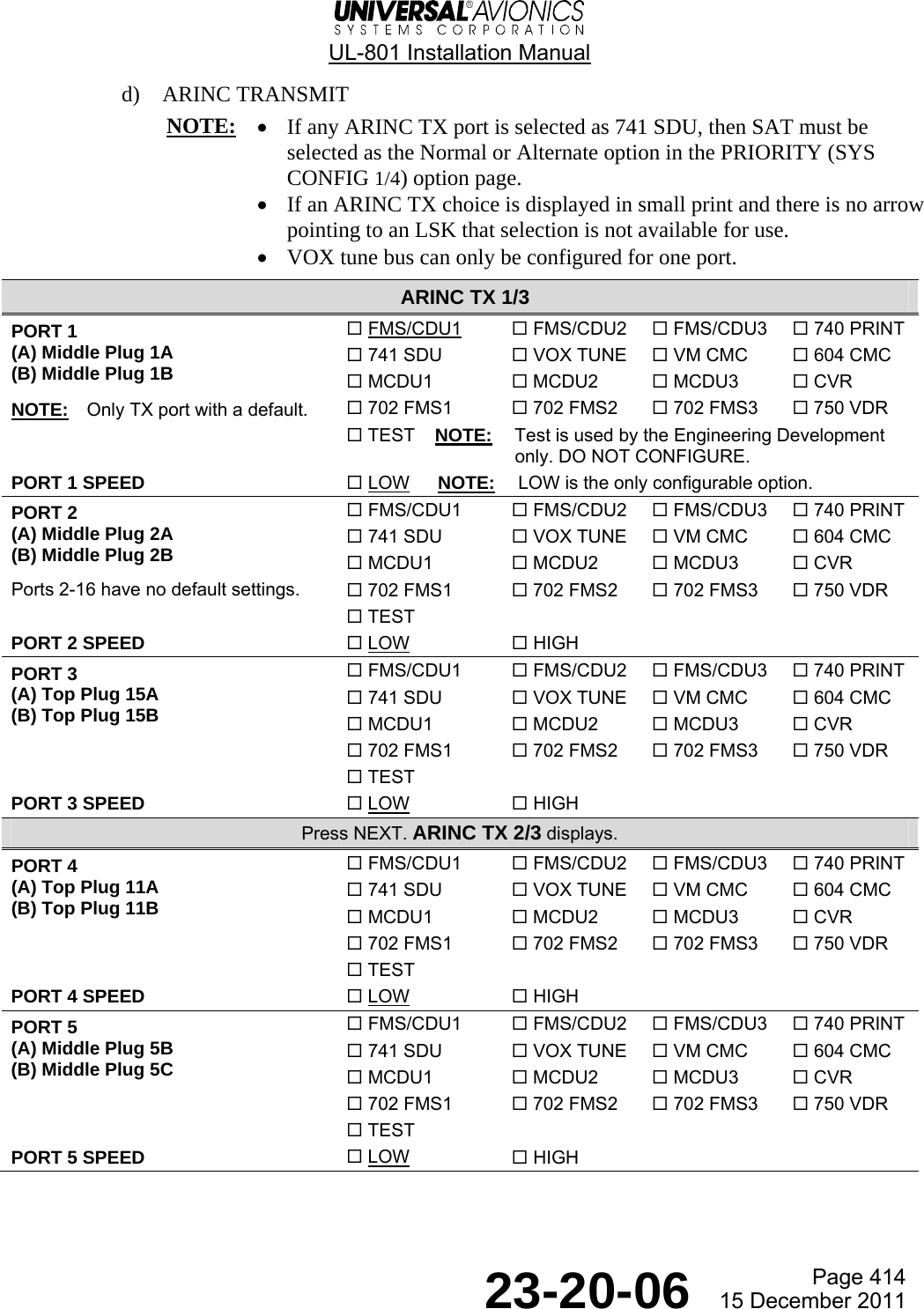
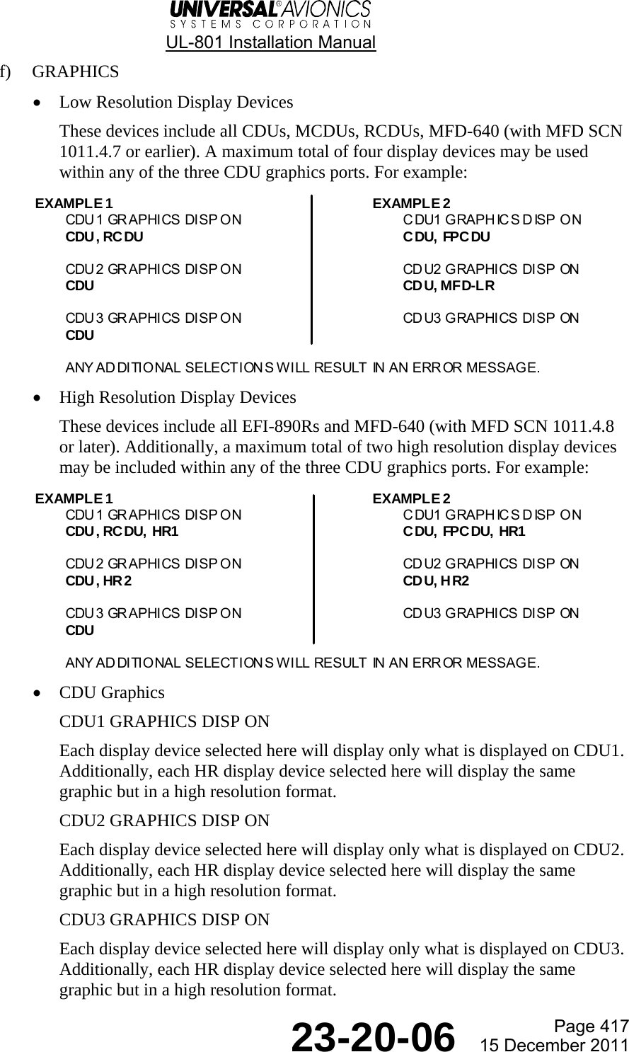
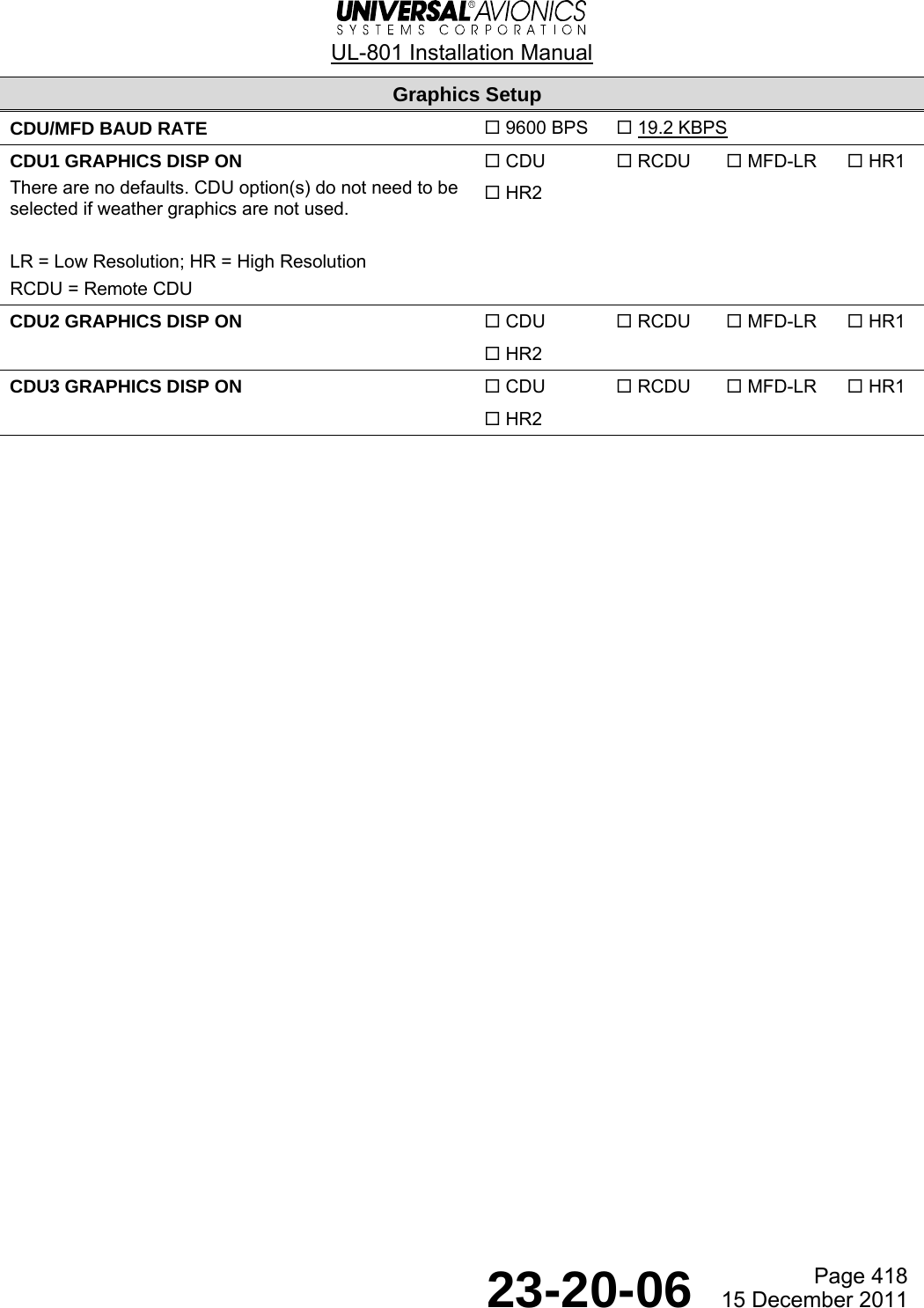
![UL-801 Installation Manual Page 445 23-20-06 15 December 2011 (6) Graphics I/O CONFIG¬DISCRETE IN SERIAL®¬DISCRETE OUT GRAPHICS®¬ARINC RECEIVE¬ARINC TRANSMIT --:--z¬UNILINK MENU RETURN®1Press GRAPHICS [2R] todisplay the GRAPHICS page.GRAPHICScdu/mfd baud rate¡ª.kbps STORE®cdu¡ graphics disp on-cdu graphics disp on-cdu£ graphics disp on- --:--z¬UNILINK MENU RETURN®5When all CDU graphics displays are configured, press RETURN twice to return to theSYS CONFIG 1/4 page.3Press LSK [2L] to display and selectthe graphics configuration for CDU1.CDU# GRAPHICS¬CDU<*> HR1®¬RCDU HR2®¬MFD-LR --:--z¬UNILINK MENU RETURN®4Graphics options are CDU, RCDU,MFD-LR, HR1, and HR2. An <*> appearsto indicate that the item is selected.Press the LSK again and <*> disappears.All or none of the options may bechosen.Press RETURN to return to theGRAPHICS page.2Press CDU/MFD BAUD RATE [1L]to toggle between 9600BPS and19.2KBPS.6Repeat steps 3 and 4 for CDU2 and CDU3.](https://usermanual.wiki/Universal-Avionics-Systems/10801.Users-Manual-6/User-Guide-1641691-Page-169.png)
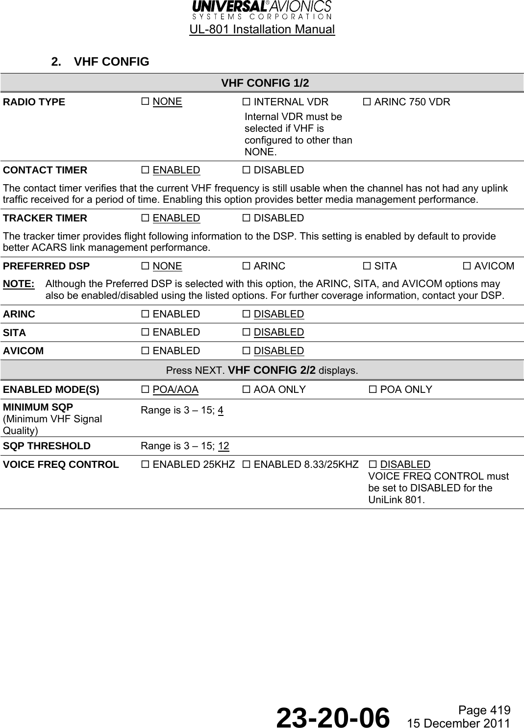
![UL-801 Installation Manual Page 446 23-20-06 15 December 2011 J. VHF Configuration VHF CONFIG 1/2radio typeINTERNAL VDR STORE®contact timer arincENABLED DISABLEDtracker timer sitaENABLED DISABLEDpreferred dsp avicomNONE DISABLED --:--z¬UNILINK MENU RETURN®1Push VHF CONFIG [2L]to display the VHFCONFIG 1/2 page.SYS CONFIG 1/4¬I/O CONFIG STORE®¬VHF CONFIG TEL CONFIG®¬SAT CONFIG POS REPORT®¬PRIORITY --:--z¬UNILINK MENU REVIEW®2Push RADIO TYPE [1L] to cyclethrough the RADIO TYPE options.Push all other configurationoptions to cycle through andchoose the options.VHF CONFIG 2/2enabled mode(s)POA/AOA STORE®minimum sqp4sqp threshold12voice freq controlDISABLED --:--z¬UNILINK MENU RETURN®4Push ENABLED MODE(S) [1L] tocycle through the ENABLEDMODE(S) options. Push all otherconfiguration options to cyclethrough and choose the options.3Push NEXT to display the VHFCONFIG 2/2 page.5Push RETURN to display the SYSCONFIG 1/4 page.](https://usermanual.wiki/Universal-Avionics-Systems/10801.Users-Manual-6/User-Guide-1641691-Page-170.png)
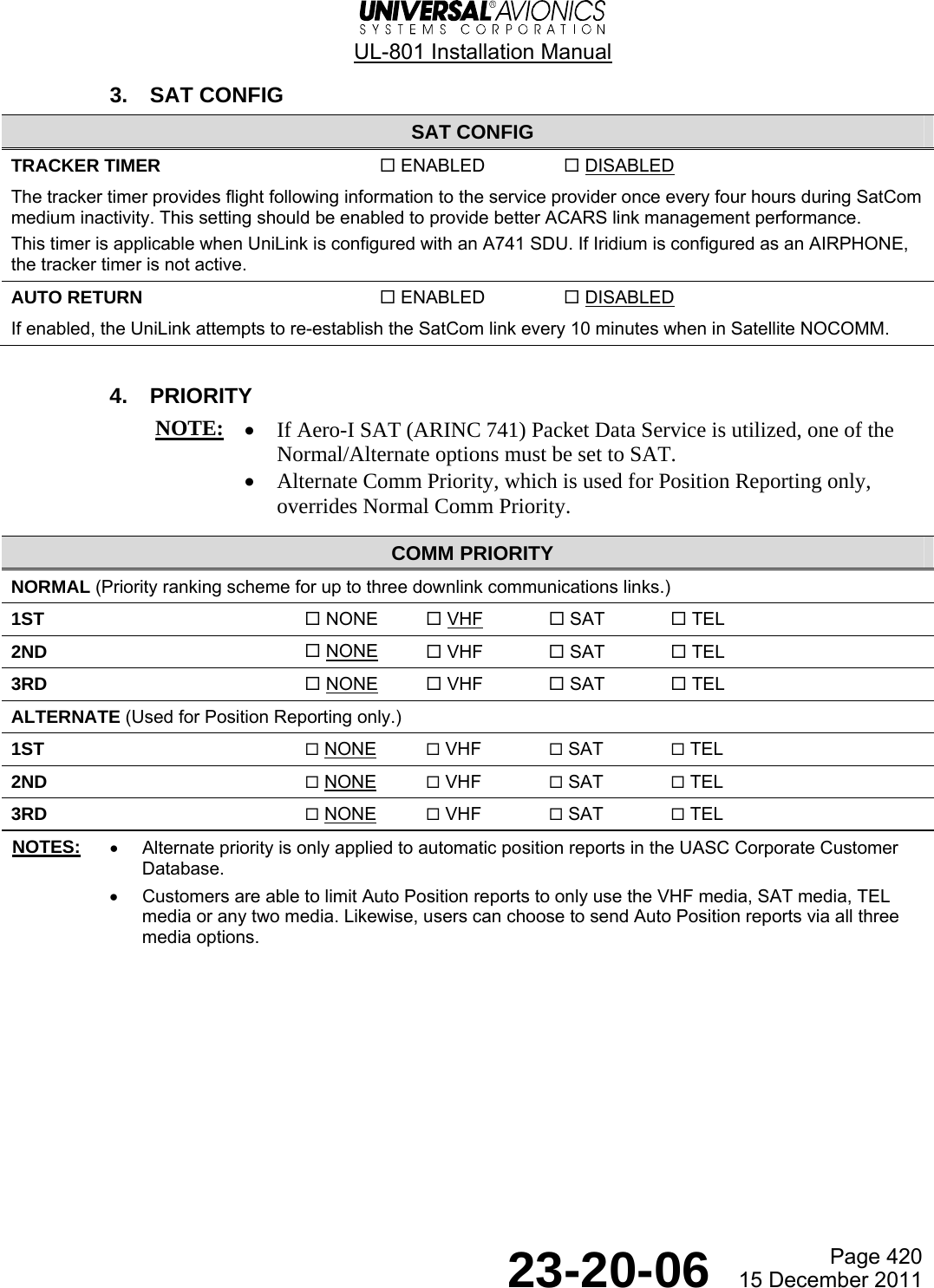
![UL-801 Installation Manual Page 447 23-20-06 15 December 2011 K. Satellite (SAT) Configuration 1Press SAT CONFIG [3L]to display the SATCONFIG page.2Press TRACKER TIMER[1L] and select ENABLEDor DISABLED. Press AUTORETURN [2L] and selectENABLED or DISABLED.3Press RETURN [5R] to theSYS CONFIG 1/4 page.SAT CONFIGtracker timerENABLED STORE®auto returnENABLED --:--z¬UNILINK MENU RETURN®SYS CONFIG 1/4¬I/O CONFIG STORE®¬VHF CONFIG TEL CONFIG®¬SAT CONFIG POS REPORT®¬PRIORITY REVIEW® --:--z¬UNILINK MENU](https://usermanual.wiki/Universal-Avionics-Systems/10801.Users-Manual-6/User-Guide-1641691-Page-171.png)
![UL-801 Installation Manual Page 448 23-20-06 15 December 2011 L. Priority Configuration 1Press PRIORITY [4L] todisplay the COMMPRIORITY page.2Press 1ST [2L] to cyclethrough the NORMAL options.Based on which option ischosen, not all optionswill be seen for eachchoice. Repeat for 2ND [3L]and 3RD [4L].COMM PRIORITY STORE®normal alternate¬¡st sat none ¡st®¬nd none none nd®¬£rd none none £rd® --:--z¬UNILINK MENU RETURN®SYS CONFIG 1/4¬I/O CONFIG STORE®¬VHF CONFIG TEL CONFIG®¬SAT CONFIG POS REPORT®¬PRIORITY REVIEW® --:--z¬UNILINK MENU3Press 1ST [2R] to cyclethrough the ALTERNATEoptions. Based on whichoption is chosen, not alloptions will be seen foreach choice. Repeat for 2ND[3R] and 3RD [4R].4Press RETURN [5R] to show theSYS CONFIG 1/4 page.](https://usermanual.wiki/Universal-Avionics-Systems/10801.Users-Manual-6/User-Guide-1641691-Page-172.png)
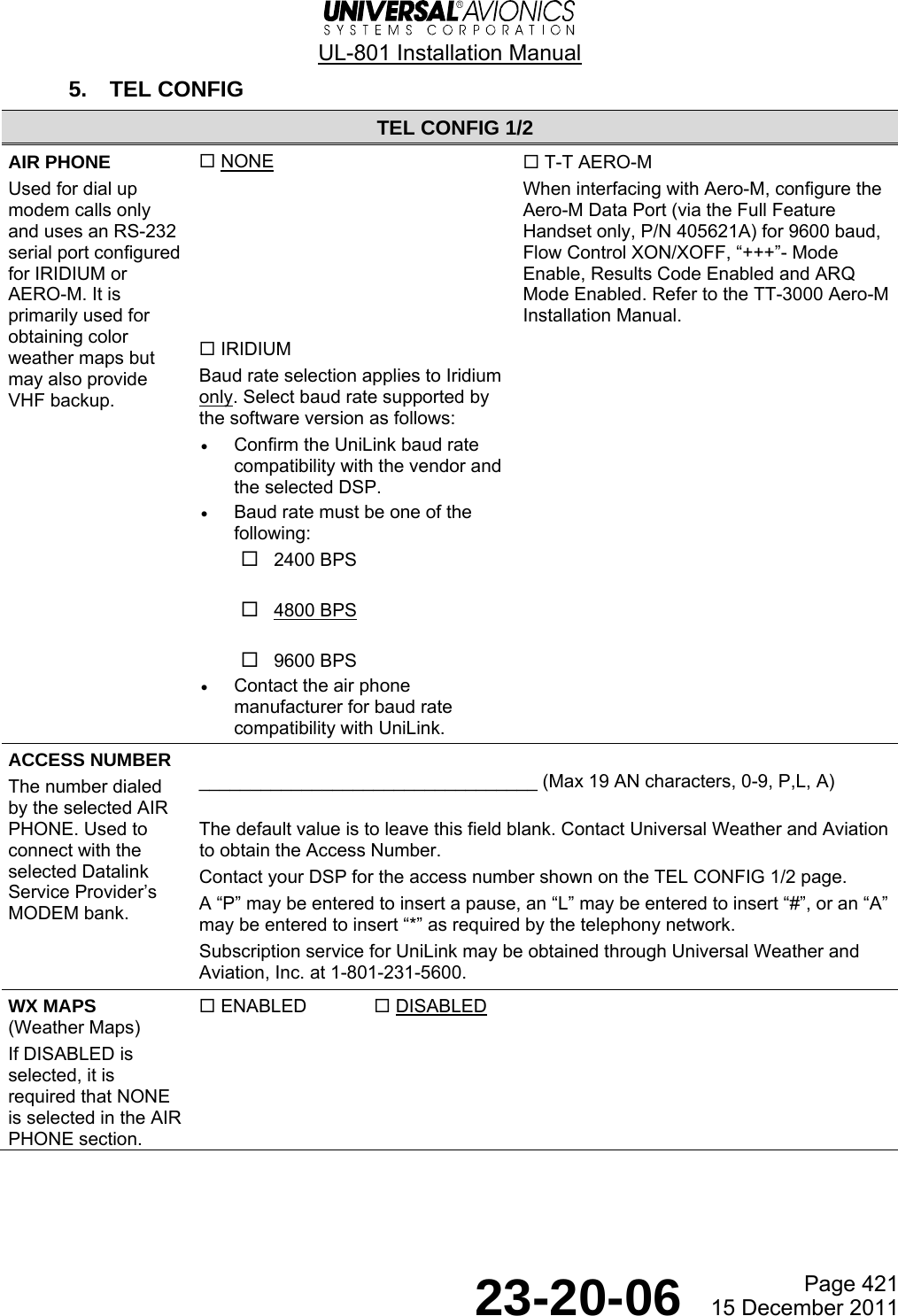
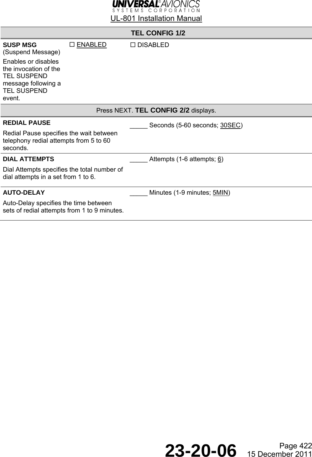
![UL-801 Installation Manual Page 449 23-20-06 15 December 2011 M. Telephony (TEL) Configuration SYS CONFIG 1/4¬I/O CONFIG STORE®¬VHF CONFIG TEL CONFIG®¬SAT CONFIG POS REPORT®¬PRIORITY REVIEW® --:--z¬UNILINK MENU1Press TEL CONFIG [2R] todisplay the TEL CONFIG 1/2page.5Press NEXT to display theTEL CONFIG 2/2 page.Press REDIAL PAUSE [1L] andenter a pause of 5 to 60seconds.Press DIAL ATTEMPTS [2L] andenter a number of dial attemptsof 1 to 6.Press AUTO-DELAY [3L] andenter a delay of 1 to 9 minutes.2Press AIR PHONE [1L] toselect the option fortelephony communications.3Press ACCESS NUMBER [2L] andenter up to 19 alphanumericcharacters for the primarytelephone access number.Press ENTER when completed.NOTE: Contact your DSP toobtain the correct accessnumber.4Press WX MAPS [3L] to toggle the ENABLEDor DISABLED option for each. Repeat forSUSP MSG [4L].NOTE: If IRIDIUM is chosen as the AIRPHONE option, WX MAPS, in the windowabove, displays a BAUD RATE option thatcan be selected at LSK [3R]. TEL CONFIG 1/2air phoneIRIDIUM STORE®access number-------------------wx mapsDISABLED BAUD RATE ¢ººbpssusp msgENABLED --:--z6Press RETURN [5R] to displaythe SYS CONFIG 1/4 page. TEL CONFIG 2/2redial pause£ºsec STORE®dial attempts§auto-delaymin --:--z¬UNILINK MENU RETURN®](https://usermanual.wiki/Universal-Avionics-Systems/10801.Users-Manual-6/User-Guide-1641691-Page-173.png)
![UL-801 Installation Manual Page 450 23-20-06 15 December 2011 N. Position Report Configuration 1Press POS REPORT [3R]to display the POSREPORT page.2Press AUTOMATICREPORTING: IN AIR[2L] and selectENABLED OR DISABLED.3Press ON GROUND [3L]and and selectENABLED OR DISABLED.POS REPORTautomaticreporting: STORE®in air air intvENABLED 15MINSon ground ground intvDISABLED 60MINSin air defaultDISABLED --:--z¬UNILINK MENU RETURN®4Press IN AIR DEFAULT [4L]and select ENABLED ORDISABLED.5Press AIR INTV [2R] andenter the number ofminutes.SYS CONFIG 1/4¬I/O CONFIG STORE®¬VHF CONFIG TEL CONFIG®¬SAT CONFIG POS REPORT®¬PRIORITY REVIEW® --:--z¬UNILINK MENU7Press RETURN [5R] to displaythe SYS CONFIG 1/4 page andperform the ConfigurationReview.6Press GROUND INTV [3R]and enter the number ofminutes.](https://usermanual.wiki/Universal-Avionics-Systems/10801.Users-Manual-6/User-Guide-1641691-Page-174.png)
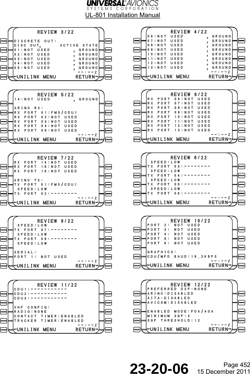
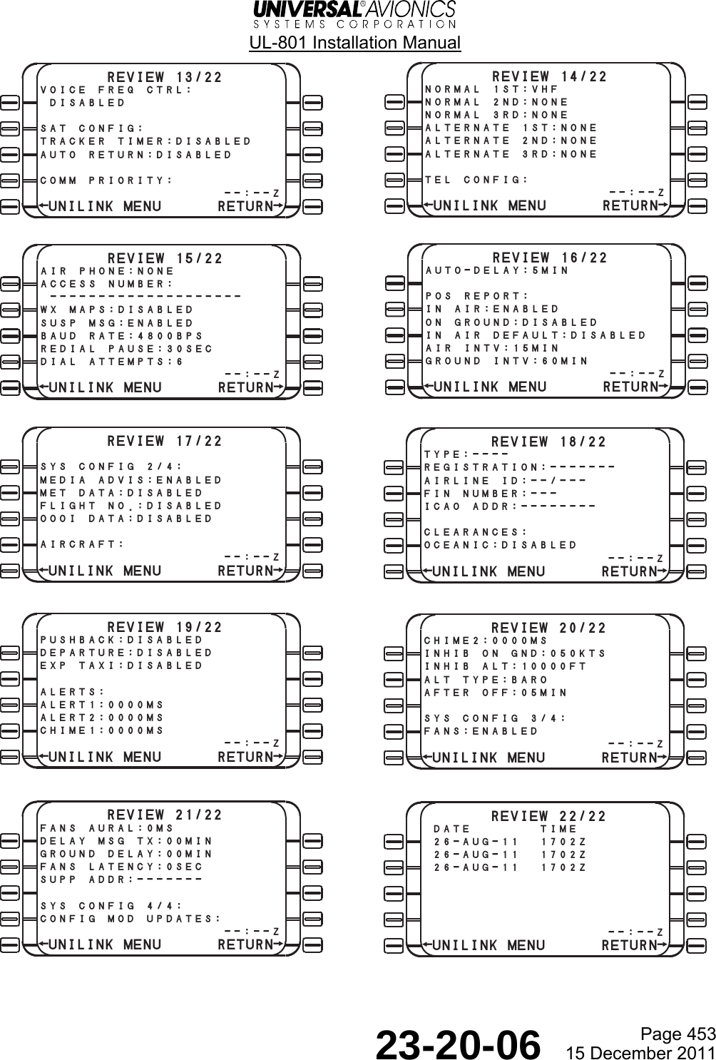
![UL-801 Installation Manual Page 451 23-20-06 15 December 2011 O. Configuration Review 1Press REVIEW [4R] todisplay the REVIEW 1/22page. REVIEW 1/22discrete in:disc in, active stateº¡:not used , groundº:not used , ground¬PRINT SEND® --:--z¬UNILINK MENU RETURN® SYS CONFIG 1/4¬I/O CONFIG STORE®¬VHF CONFIG TEL CONFIG®¬SAT CONFIG POS REPORT®¬PRIORITY REVIEW® --:--z¬UNILINK MENUNOTE: The REVIEW pages are a visual representation of the contents of theUniLink Configuration Module. After reviewing all pages for errors, pressNEXT on the keypad to return to the REVIEW Page 1. If theconfiguration is correct, press RETURN LSK [5R] to display SYS CONFIG 1/4.Press STORE [1R] twice to save the configuration. If errors were noted during thereview, it will be necessary to return to the appropriate configuration pageto make the changes. REVIEW 2/22º£:not used , groundº¢:not used , groundº:not used , groundº§:not used , groundº¶:not used , groundº:not used , groundºª:not used , ground¡º:not used , ground --:--z¬UNILINK MENU RETURN®3Press NEXT to display the eachsequential review page.2Press SEND [4R] to transmit aConfiguration Report downlink.NOTE: When SEND is pressed, theQUEUED message displays over theSEND LSK.](https://usermanual.wiki/Universal-Avionics-Systems/10801.Users-Manual-6/User-Guide-1641691-Page-175.png)
![UL-801 Installation Manual Page 501 23-20-06 15 December 2011 Maintenance, Checkout, and Troubleshooting 1. UniLink Ground Checkout Procedures A. Post Installation Test For instructions on testing the UniLink following the initial installation in an aircraft, the installer should refer to the installation Ground and/or Flight Test Plans that are part of the UniLink installation (TC, STC, Field Approval) certification package. The installation approval applicant should contact Universal Avionics Certification Department for Ground and/or Flight Test Plan templates that can be used for developing customized test plans. B. Return to Service The following defines the conditions under which tests, specified below, should be conducted. (1) Safety Precautions User should follow all appropriate safety precautions. (2) Power Input Unless otherwise specified, tests should be conducted with the equipment powered by the aircraft’s electrical power generating system. (3) Associated Equipment or Systems Unless otherwise specified, turn on all aircraft electrically operated equipment and systems before conducting these tests. (4) Environment During tests, the equipment should not be subjected to environmental conditions that exceed those specified by the equipment manufacturer. (5) Warm-up Period No warm-up period is required. However, some time must be allowed for all associated equipment to boot up properly and stabilize. C. UniLink to FMS/CDU Communications NOTE: This procedure should be completed for each FMS/CDU connected to the UniLink. (1) Verify that DATA 1/4 page is displayed an active UNILINK prompt. (2) From the DATA 1/4 page, press the UNILINK LSK [3R] and verify the UNILINK MENU 1/2 page is displayed. (3) Press RETURN LSK [5R]. Verify that the DATA 1/4 page is displayed. (4) Repeat test steps 1 through 3 for each FMS/CDU connected and configured for UniLink.](https://usermanual.wiki/Universal-Avionics-Systems/10801.Users-Manual-6/User-Guide-1641691-Page-179.png)
![UL-801 Installation Manual Page 502 23-20-06 15 December 2011 D. Version Check (1) From the UNILINK MENU Page 1, press NEXT. (2) Press MAINTENANCE LSK [4L]. (3) Press VERSIONS LSK [3L]. (4) Verify the correct UniLink SCN and Part Number appears on the screen. E. Device Status (1) Ensure all peripheral devices are powered on. (2) Press the DEVICE STATUS LSK [1L] on the MAINTENANCE 1/3 page. (3) Verify that the device status is OK for all applicable configured peripheral devices such as FMSs, MCDUs, CDUs, low and high resolution graphics devices, and CVRs. Press NEXT to cycle thru the DEVICES pages. F. UniLink to Display Processor RS-422 Communications This procedure applies only to display devices wired and configured to support weather graphics. (1) From the MAINTENANCE 1/3 page, press the TESTS LSK [2R]. (2) Press the IMAGE LSK [2L]. (3) The IMAGE TEST IN PROGRESS pop-up message will appear. (4) Verify that the test image below is presented on all appropriate display devices. NOTE: • This is a Low Resolution test image and will be displayed as such on High Resolution display devices as well. UniLink does not generate a High Resolution test image. • It is recommended that you delete the test image following test completion.](https://usermanual.wiki/Universal-Avionics-Systems/10801.Users-Manual-6/User-Guide-1641691-Page-180.png)
![UL-801 Installation Manual Page 503 23-20-06 15 December 2011 G. UL-801 VHF Communications VHF datalink service coverage on the ground may be limited. Coverage may be affected by ground obstacles and may be restricted due to poor line of sight of the VHF ground station antenna. (1) The VHF communications status is indicated on the UniLink COMM STATUS page. Press COMM STATUS LSK [4L] on the UNILINK MENU 1/2 page. (2) If VHF COMM STATUS is COMM/IDLE, a request for ATIS information can be performed on the ground. Otherwise, if the VHF COMM STATUS is NOCOMM/SCANNING, the aircraft should be relocated elsewhere until the status of COMM/IDLE is obtained. (3) To request D-ATIS, from the UNILINK MENU Page 1: • Press the FLIGHT INFO LSK. • Press the D-ATIS LSK. • Press AIRPORT. Type KORD, for example, or your airport identifier. • Press LSK [ENTER]. • Press SEND to transmit the request. − If QUEUED is displayed above the SEND prompt, the VHF probably is not connected to the ACARS system. − If Sending, SENT is displayed. The request was received and acknowledged. Your request will be shortly received by UniLink and available for viewing. H. OOOI Sensor Test (4) Ensure Door and Park Brake discrete inputs are connected and configured. (1) From UNILINK MENU 2/2 page, press the MAINTENANCE LSK [4L]. (2) Press SENSOR STATUS LSK [2L]. (3) Open and close the door. (4) Verify the DOORS status changes accordingly. (5) Release and set parking brake. (6) Verify the BRAKE status changes accordingly. (7) Verify the AIR/GROUND status is ON GROUND. NOTE: If the aircraft is on jacks, the status will be IN AIR.](https://usermanual.wiki/Universal-Avionics-Systems/10801.Users-Manual-6/User-Guide-1641691-Page-181.png)
![UL-801 Installation Manual Page 504 23-20-06 15 December 2011 I. Printer Test (1) Verify that printer power is on and has passed its self-test. (2) With the DATA page 1/4 displayed, press UNILINK LSK [3R]. The UNILINK MENU 1/2 will display. (3) Press the NEXT key. (4) Press MAINTENANCE LSK [4L] to display the MAINTENANCE 1/3 page. (5) Press TESTS LSK [2R] to display the TESTS page. (6) Press PRINTER LSK [1L]. The printing message pop-up message will display and a test pattern will be sent to the printer. (7) The TESTS page will again display. J. Checking the UL-801 FANS ALERTS Output Discretes This procedure applies only to FANS-enabled aircraft. (1) From the DATA 1/4 page, press UNILINK LSK [3R]. The UNILINK MENU 1/2 page will display. (2) Press the NEXT key. (3) Press MAINTENANCE LSK [4L] to display the MAINTENANCE 1/3 page. (4) Press TESTS LSK [2R] to display the TESTS page. (5) Press FANS ALERTS LSK [1R]. The FANS DISCRETE TEST IN PROGRESS pop-up message will appear. (6) Verify that all appropriate FANS Visual and Aural alerts activate momentarily. K. Checking the UL-801 Self-Test (Optional) This test simply reboots the UniLink. After the reboot process, verify that the UniLink prompt becomes active. L. Checking the UL-801 Weather Graphics using a SatCom-based Telephony System NOTE: Ensure that the selected DSP supports Weather Graphics uplinks. (1) Press the DATA key to display the DATA 1/4 page. (2) Press UNILINK LSK [3R] to display UNILINK MENU 1/2. (3) Press WX MAPS LSK [2R] to display the WX MAP REQUEST page. (4) Press SIG WX LSK [2R] and the SIGNIFICANT WX page will display. (5) Press SEND LSK [4R]. This prompts UniLink to place a call to the selected DSP. (6) The QUEUED and SENDING messages display. After a few minutes, the FMS UniLink will display NEW WX ADVISORY under the ADVISORY area. Press the LSK to the left of the ADVISORY message to display the message. a) If a UniLink page is not currently displayed on the FMS, the MSG icon light will flash. (7) Press the MSG key on the FMS to display the MESSAGES 1/X page. The UNILINK WX MAP RCVD message will appear. (8) Pressing the UniLink prompt will display the UNILINK MENU 1/2 page.](https://usermanual.wiki/Universal-Avionics-Systems/10801.Users-Manual-6/User-Guide-1641691-Page-182.png)
![UL-801 Installation Manual Page 505 23-20-06 15 December 2011 (9) Press LSK [5L] to display the weather map. Verify that the correct map has been received. M. Checking the UL-801 ARINC 741 SatCom (SAT) NOTE: Ensure that the selected DSP provides this service. (1) Verify that the SatCom SDU is powered up, initialized, and logged on. (2) From the UNILINK MENU 1/2 page, press COMM STATUS. (3) If the SatCom status is NOCOMM/UNAVAILABLE, UniLink has not detected label 270 from the SatCom. This indicates the Sat Link is unavailable. (4) If the SatCom status is NOCOMM/CONNECTING, the SatCom Link is available, UniLink will send a Link Test message, and wait for an acknowledgement from the ACARS network to confirm connectivity to the network. (5) If SatCom status is COMM/IDLE, the SatCom Link connectivity to the ACARS network has been confirmed and UniLink is ready to send and receive messages via the SatCom link. All tests are now complete.](https://usermanual.wiki/Universal-Avionics-Systems/10801.Users-Manual-6/User-Guide-1641691-Page-183.png)
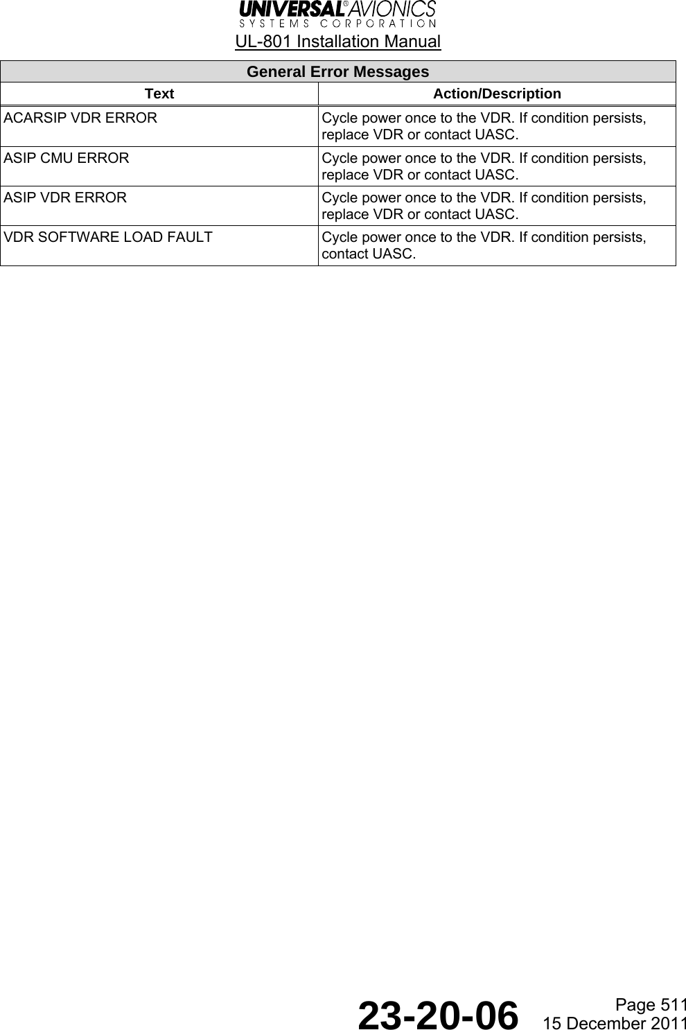
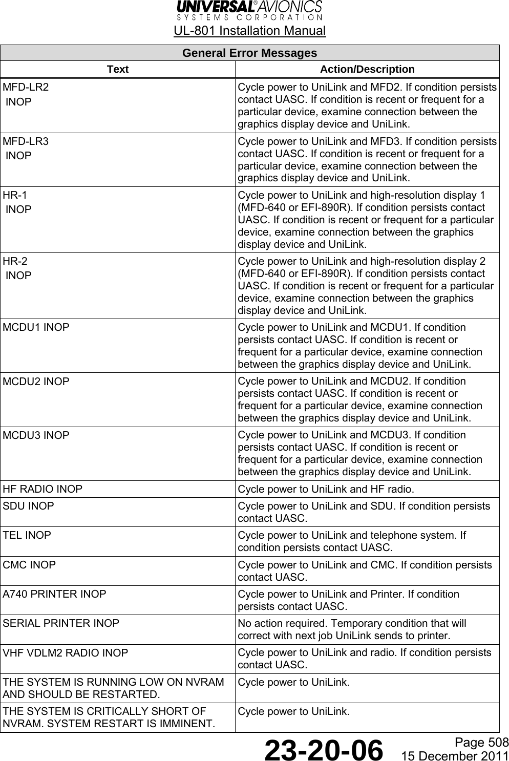
![UL-801 Installation Manual Page 507 23-20-06 15 December 2011 B. General Error Messages UniLink error messages may be found by using either of the following two processes: (1) Press the MSG key to see the messages. a) Press the NEXT key to scroll through the messages. (2) Press the MAINTENANCE LSK [4L] on the UNILINK MENU 1/2 page. a) Press the ERROR LOG LSK [4L] on the MAINTENANCE 1/3 page. NOTE: The Error Log contains all error messages including configuration error messages. The messages found when pressing the MSG key are only applicable to configuration errors. b) Press the NEXT key to scroll through the messages. General Error Messages Text Action/Description FMS1 INOP Cycle power to UniLink and FMS1. If condition persists contact UASC. FMS2 INOP Cycle power to UniLink and FMS2. If condition persists contact UASC. FMS3 INOP Cycle power to UniLink and FMS3. If condition persists contact UASC. CDU1 DP INOP Cycle power to UniLink and CDU1. If condition persists contact UASC. If condition is recent or frequent for a particular device, examine connection between the graphics display device and UniLink. CDU2 DP INOP Cycle power to UniLink and CDU2. If condition persists contact UASC. If condition is recent or frequent for a particular device, examine connection between the graphics display device and UniLink. CDU3 DP INOP Cycle power to UniLink and CDU3. If condition persists contact UASC. If condition is recent or frequent for a particular device, examine connection between the graphics display device and UniLink. REMOTE CDU1 DP INOP Cycle power to UniLink and RCDU1. If condition persists contact UASC. If condition is recent or frequent for a particular device, examine connection between the graphics display device and UniLink. REMOTE CDU2 DP INOP Cycle power to UniLink and RCDU2. If condition persists contact UASC. If condition is recent or frequent for a particular device, examine connection between the graphics display device and UniLink. REMOTE CDU3 DP INOP Cycle power to UniLink and RCDU3. If condition persists contact UASC. If condition is recent or frequent for a particular device, examine connection between the graphics display device and UniLink. MFD-LR1 INOP Cycle power to UniLink and MFD1. If condition persists contact UASC. If condition is recent or frequent for a particular device, examine connection between the graphics display device and UniLink.](https://usermanual.wiki/Universal-Avionics-Systems/10801.Users-Manual-6/User-Guide-1641691-Page-185.png)
![UL-801 Installation Manual Page 509 23-20-06 15 December 2011 General Error Messages Text Action/Description SERIAL PRINTER FAILURE Examine the printer and its serial and power connections. PRINT JOB TOO LARGE No action required. UniLink has attempted to forward a corrupted uplink to the printer. Re-request uplink data. [Hardware port] FAIL example: ARINC TX PORT 1 FAIL Cycle power to UniLink. If condition persists contact UASC. THE FATAL ERROR LOG HAS BEEN CORRUPTED No action required. Old messages are discarded and the log is automatically restarted. THE FATAL ERROR LOG CONTAINS A NEW ENTRY No action required. If condition is frequent, contact UASC. PROTOCOL ERROR LOG CORRUPT. OLD PROTOCOL ERRORS DISCARDED. LOGGING OF PROTOCOL ERRORS WILL RESTART. No action required. Old messages are discarded and protocol error logging is automatically restarted. LINK ERROR LSK [device name, count, first/last occurrence] No action required. Protocol errors are automatically corrected, usually with no impact to the user. If condition is frequent for a particular device, examine connection between device and UniLink. PROTOCOL ERROR LSK [device name, count, first/last occurrence] CTS BUSY LSK [device name, count, first/last occurrence] No action required. Protocol errors are automatically corrected, usually with no impact to the user. If condition is frequent for a particular device, examine connection between device and UniLink. CTS TIMEOUT LSK [device name, count, first/last occurrence] MSG RETRY LSK [device name, count, first/last occurrence] SYN LSK [device name, count, first/last occurrence] MSG TIMEOUT LSK [device name, count, first/last occurrence] DSC RETRY LSK [device name, count, first/last occurrence] DSC TIMEOUT LSK [device name, count, first/last occurrence] SPW RETRY LSK [device name, count, first/last occurrence] SPW TIMEOUT LSK [device name, count, first/last occurrence] TX BUF FULL LSK [device name, count, first/last occurrence] RX PORT 1: UASC FMS DETECTED. OVERRIDING PORT CONFIGURATION FOR MCDU Configure UniLink with ARINC receive port 1 as FMS/CDU1 and transmit port 1 as FMS/CDU1. RX PORT 1: MCDU DETECTED. OVERRIDING PORT CONFIGURATION FOR UASC FMS Configure UniLink with ARINC receive port 1 as MCDU1 and transmit port 1 as MCDU1.](https://usermanual.wiki/Universal-Avionics-Systems/10801.Users-Manual-6/User-Guide-1641691-Page-187.png)
![UL-801 Installation Manual Page 510 23-20-06 15 December 2011 General Error Messages Text Action/Description STATUS TIMEOUT LSK [count, first/last occurrence] No action required. Protocol errors are automatically corrected, usually with no impact to the user. If condition is frequent, examine connection between the printer and UniLink. ENQ TIMEOUT LSK [count, first/last occurrence]RECORD TIMEOUT LSK [count, first/last occurrence] RECORD RESEND LSK [count, first/last occurrence] PRINTER FAIL LSK [count, first/last occurrence]DOOR OPEN LSK [count, first/last occurrence] TEST LSK [count, first/last occurrence] INIT LSK [count, first/last occurrence] OVERRUN LSK [count, first/last occurrence] BUSY LSK [count, first/last occurrence] INVALID CTS LSK [count, first/last occurrence] ERASE FAULT LSK [device name, count, first/last occurrence] If condition is recent or frequent for a particular device, examine connection between the graphics display device and UniLink. TOO MANY FAILED SLOTS LSK [device name, count, first/last occurrence] UNEXPECTED EOF LSK [device name, count, first/last occurrence] UNKNOWN IMAGE FORMAT LSK [device name, count, first/last occurrence] GIF ERROR LSK [device name, count, first/last occurrence] TRANSMIT FAIL LSK [device name, count, first/last occurrence] INVALID GX HEADER LSK [count, first/last occurrence] If condition is recent or frequent, examine connection between telephone system and UniLink. VDL MODE A NOT SUPPORTED Cycle power once to the VDR. If condition persists, replace VDR or contact UASC. VDL MODE 2 NOT SUPPORTED Cycle power once to the VDR. If condition persists, replace VDR or contact UASC. VDR TX WARN FAULT Cycle power once to the VDR. If condition persists, replace VDR or contact UASC. VDR STATUS FAULT Cycle power once to the VDR. If condition persists, replace VDR or contact UASC. CTRL PROTOCOL CMU ERROR Cycle power once to the VDR. If condition persists, replace VDR or contact UASC. CTRL PROTOCOL VDR ERROR Cycle power once to the VDR. If condition persists, replace VDR or contact UASC. ACARSIP CMU ERROR Cycle power once to the VDR. If condition persists, replace VDR or contact UASC.](https://usermanual.wiki/Universal-Avionics-Systems/10801.Users-Manual-6/User-Guide-1641691-Page-188.png)