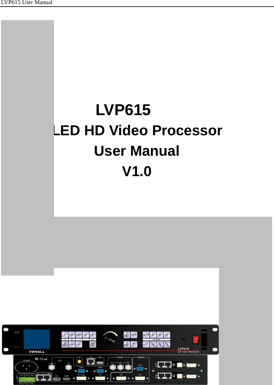
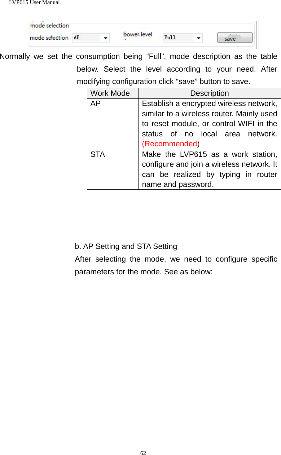
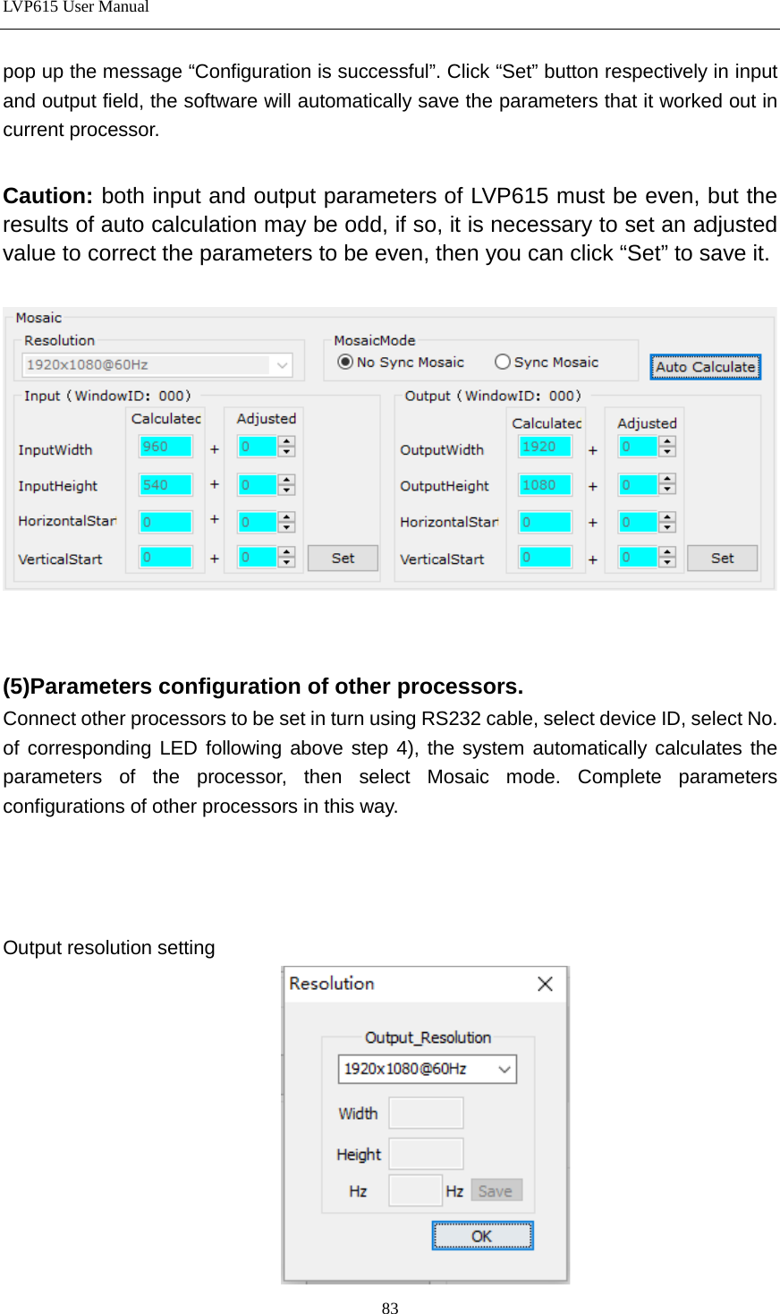
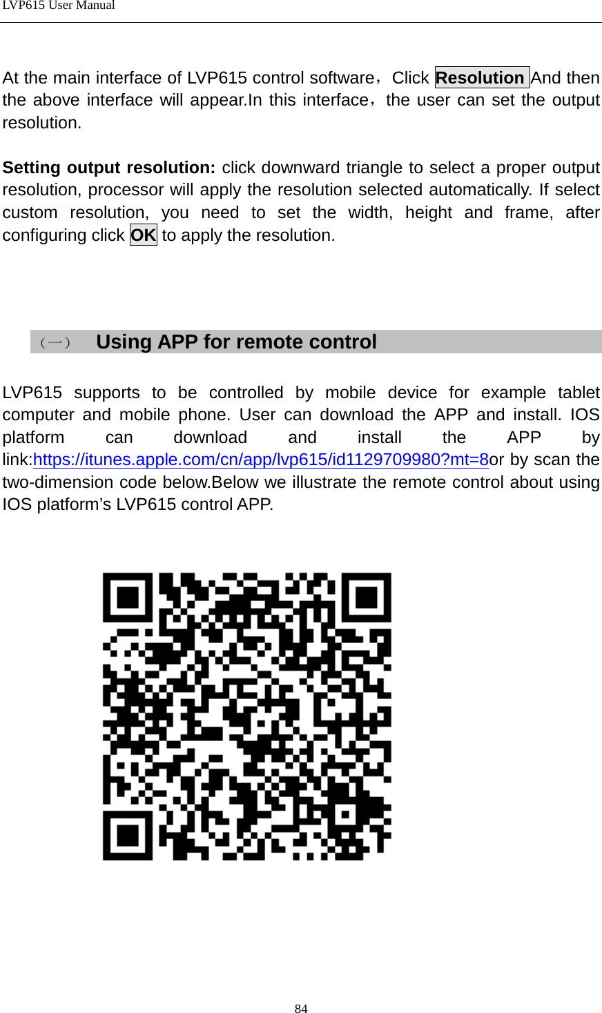
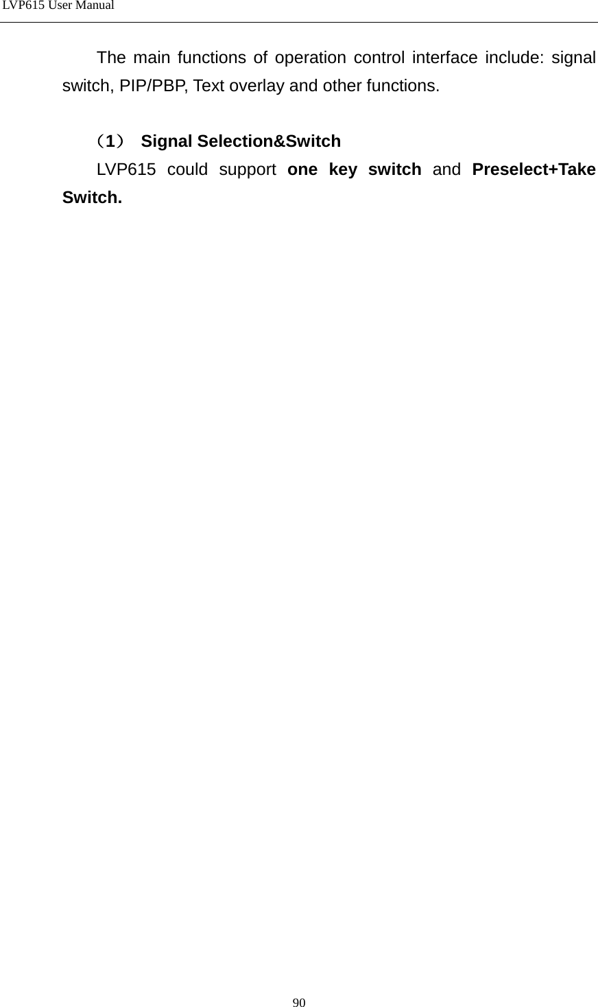
VDWALL LVP615 LED Video Processor User Manual LVP605
Shenzhen VDWALL Co., Ltd LED Video Processor LVP605
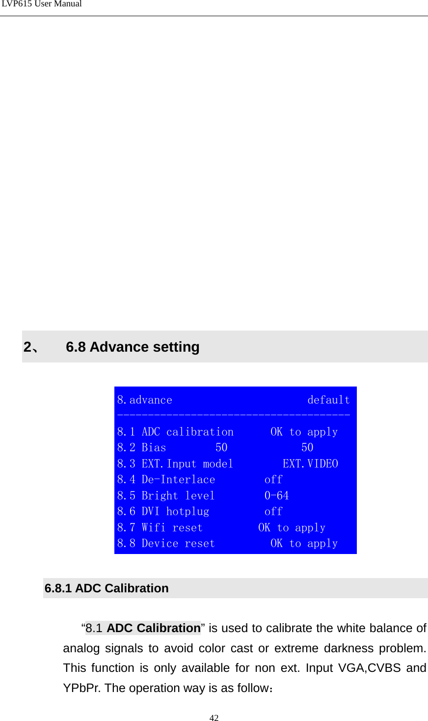
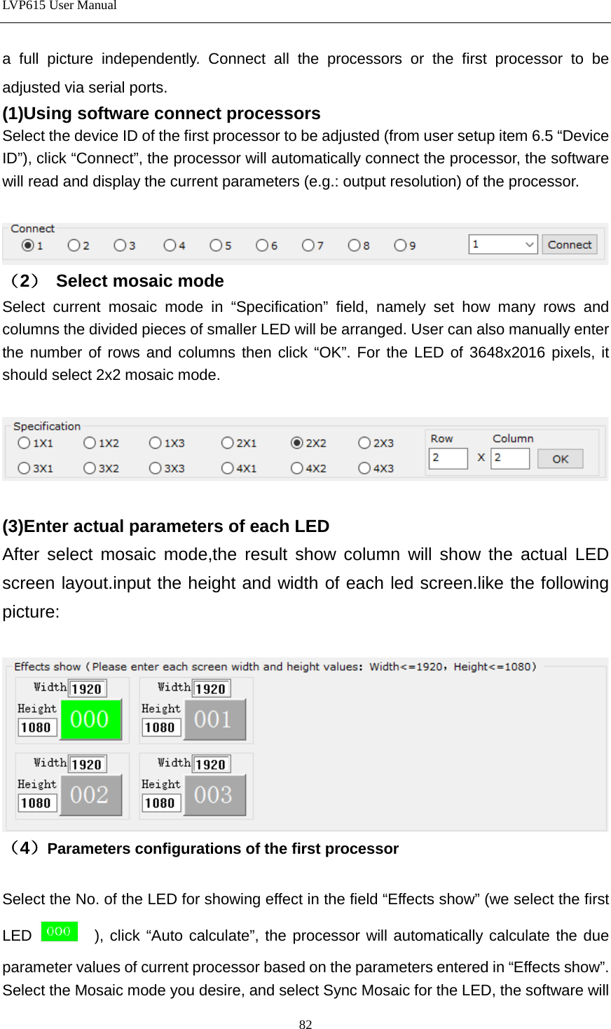
UserManual.wiki
>
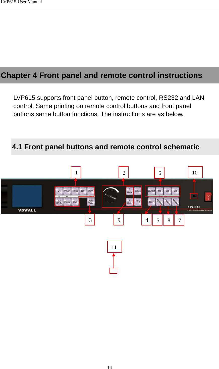
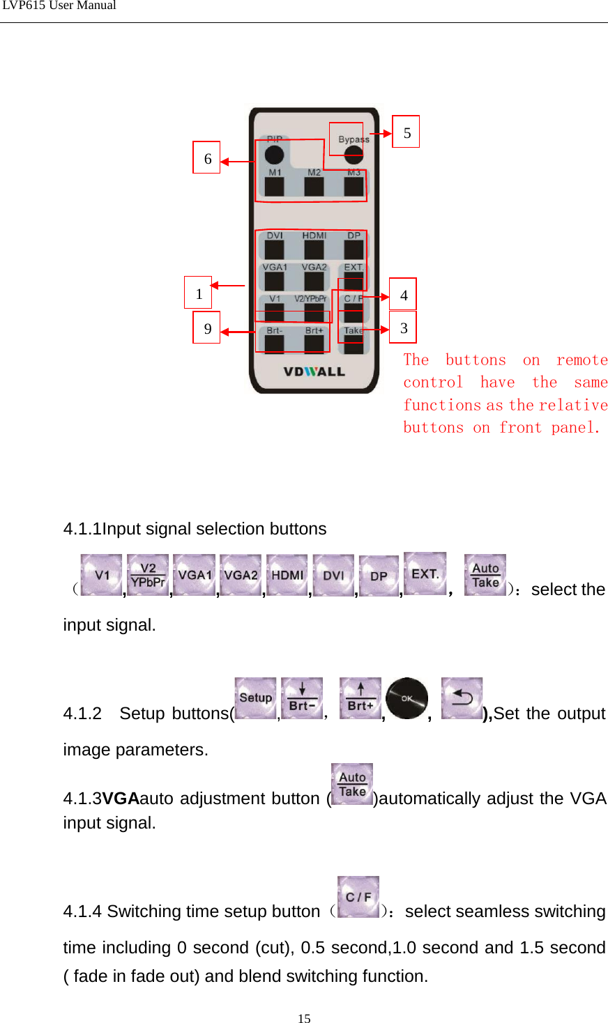
VDWALL
>
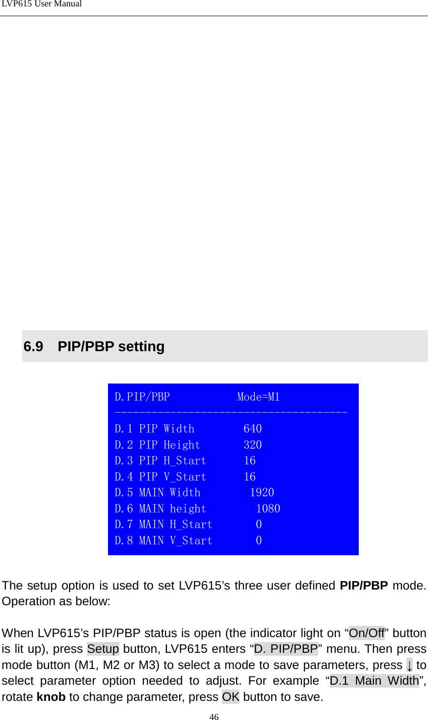
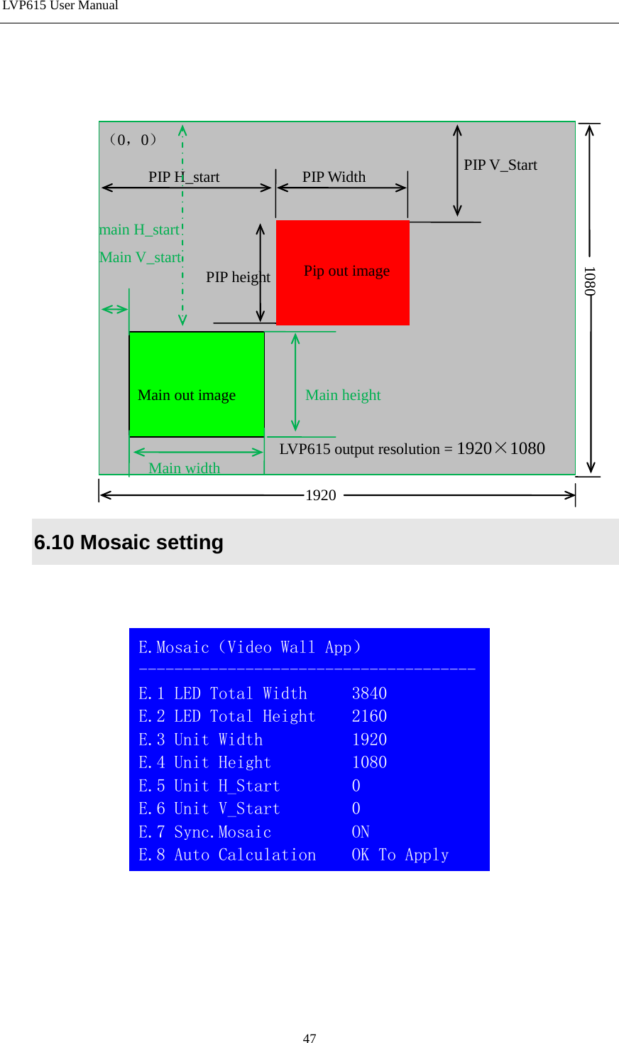
LVP615 User Manual
user manual
Navigation menu
Upload a User Manual
Namespaces
Wiki Guide
HTML
PDF
Info
Views
User Manual
Discussion / Help
Navigation