VPN Systems VPN350 Wireless LAN Adapter (Unlicensed) User Manual ap350scgb
VPN Systems, Inc. Wireless LAN Adapter (Unlicensed) ap350scgb
Contents
- 1. Users Manual
- 2. Correspondence 24174 Question 1 Users Manual Section 1
- 3. Correspondence 24174 Question 1 Users Manual Section 2
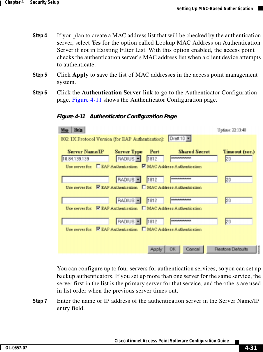
Correspondence 24174 Question 1 Users Manual Section 2
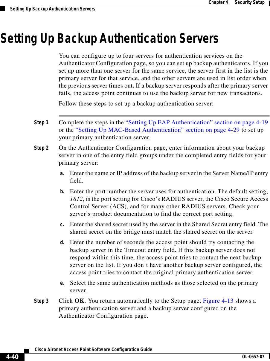
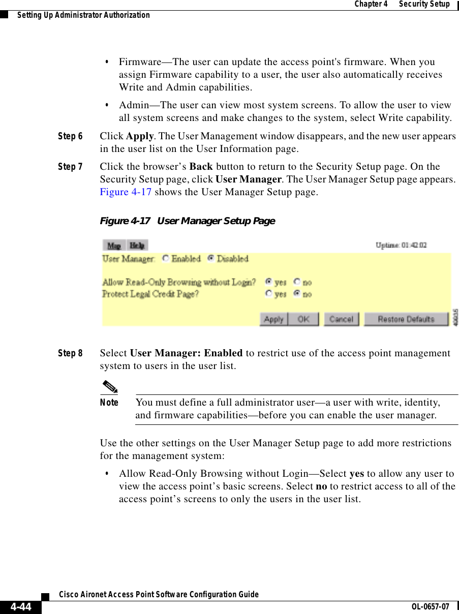

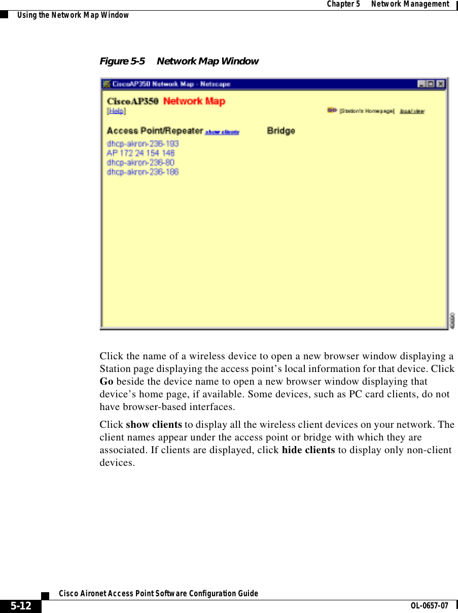
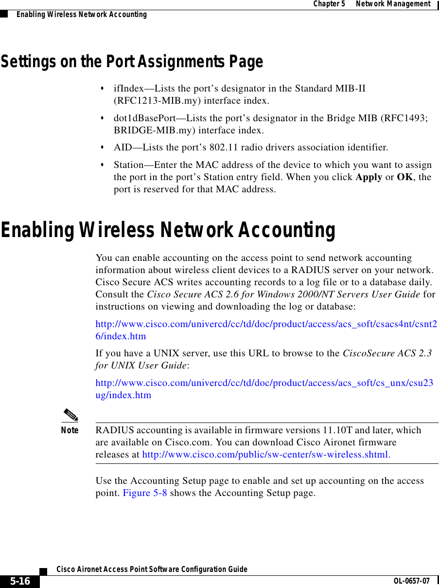
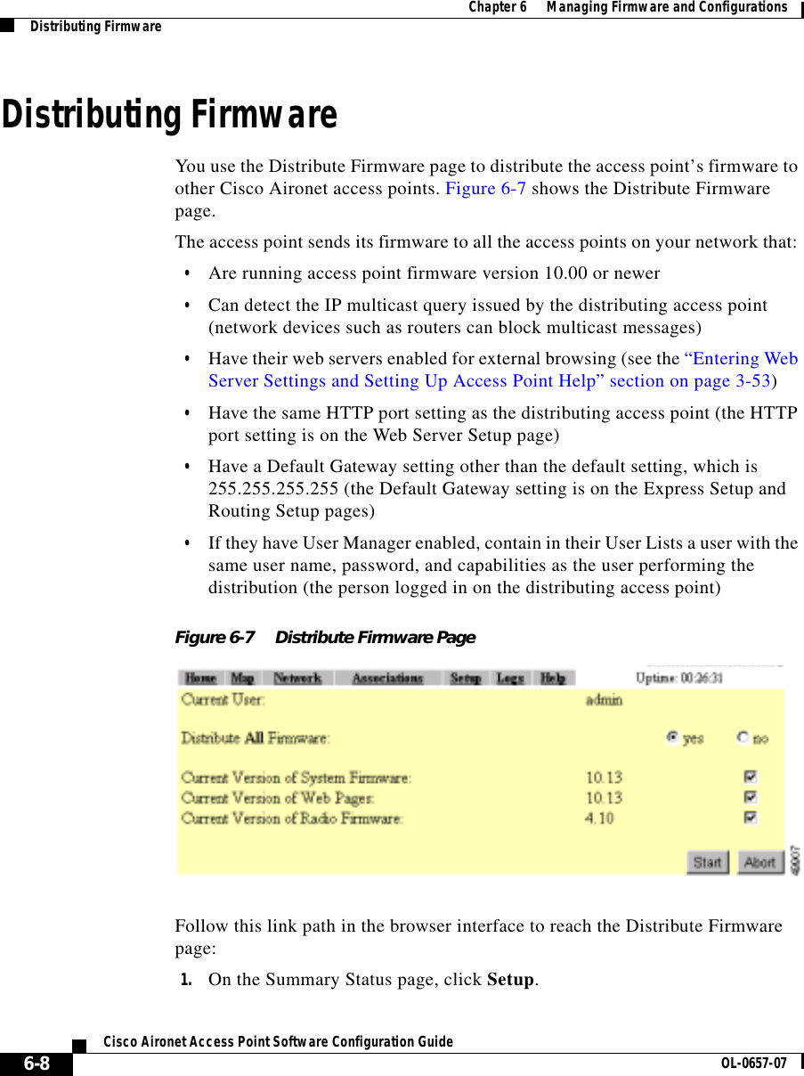
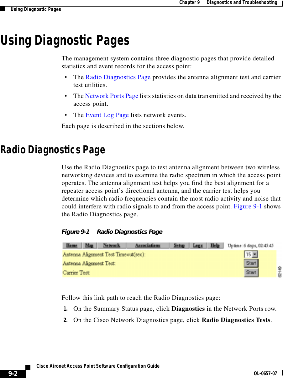
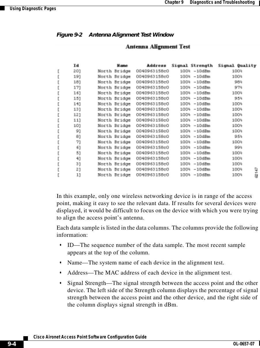
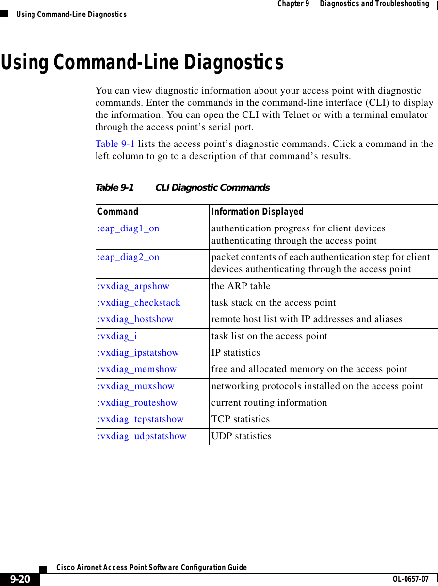
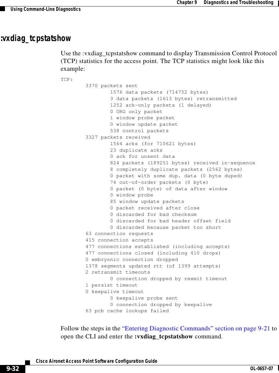
![5-7Cisco Aironet Access Point Software Configuration GuideOL-0657-07Chapter 5 Network Management Using the Association TableFrom Station InformationFields in the To Station column contain the following information:•Alert—Click this box if you want detailed packet trace information captured for the Association Table page. This option is only available to users with Administrator capability.•Packets OK—Reports the number of good packets sent from the station. •Total Bytes OK—Reports the number of good bytes sent from the station. •Total Errors—Reports the total number of packet errors sent from the station. •WEP Errors—Reports the number of encryption errors sent from the station.Rate, Signal, and Status InformationThe table under the To and From Station table lists rate, signal, and status information for the device.Data rate and signal quality information appears on Station pages for client devices. On Station pages for access points, this area shows network information such as system uptime.•Parent—Displays the system name of the device to which the client, bridge or repeater is associated. The entry [self] indicates that the device is associated with this access point.•Current Rate—Reports the current data transmission rate. If the station is having difficulty communicating with the access point, this might not be the highest operational rate.•Latest Retries—Tally of short and long data retries.•Next Hop—If repeater access points are used on the network, this field names the next access point in the repeater chain. •Operational Rates—The data transmission rates in common between the access point and the station.•Latest Signal Strength—Displays the current index of radio signal quality. The following four fields appear only on the Station page for an access point:•Stations Associated—Displays, by number and class, all stations associated with the access point.](https://usermanual.wiki/VPN-Systems/VPN350.Correspondence-24174-Question-1-Users-Manual-Section-2/User-Guide-281317-Page-23.png)
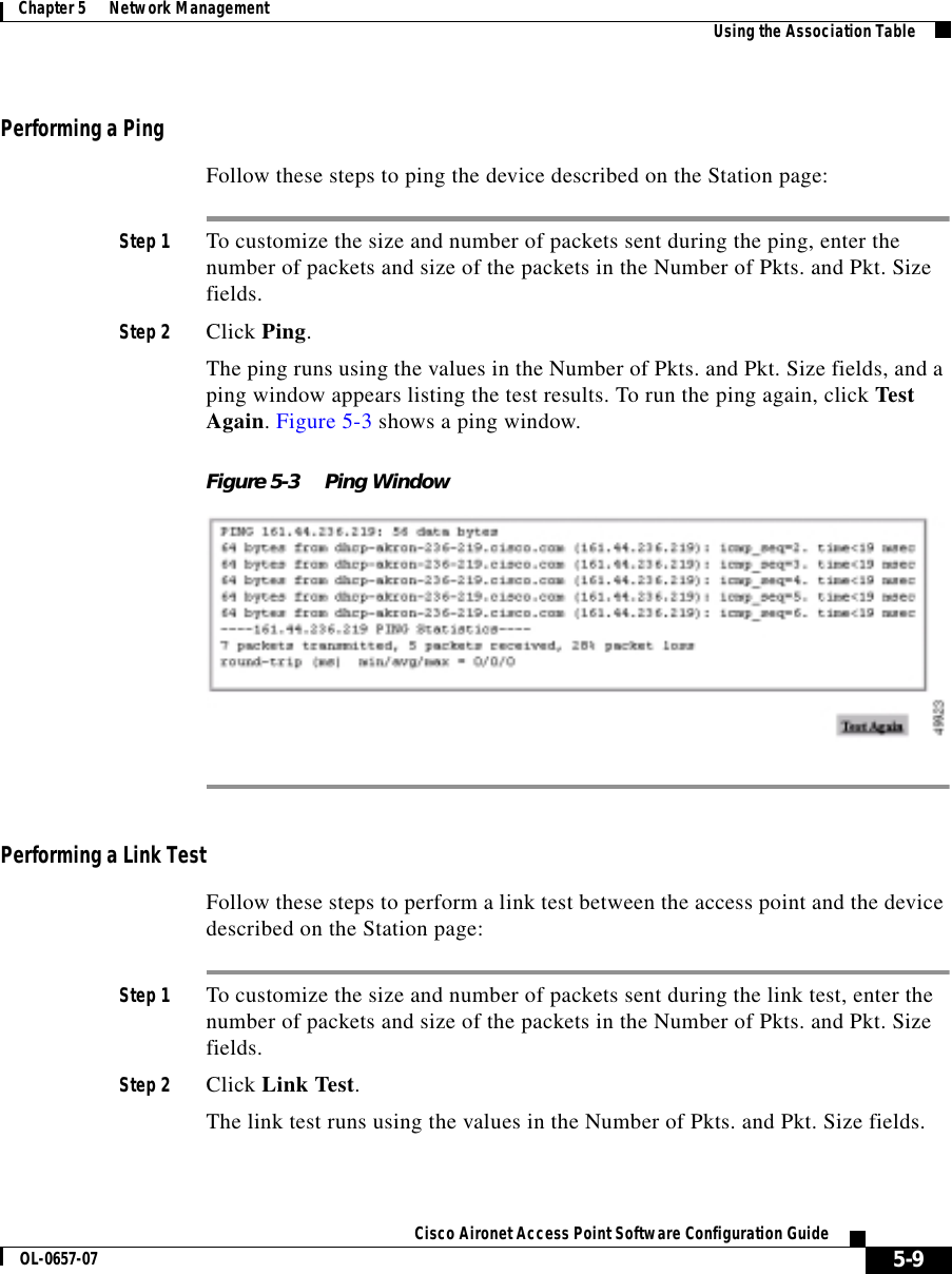
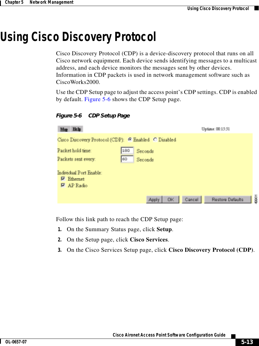
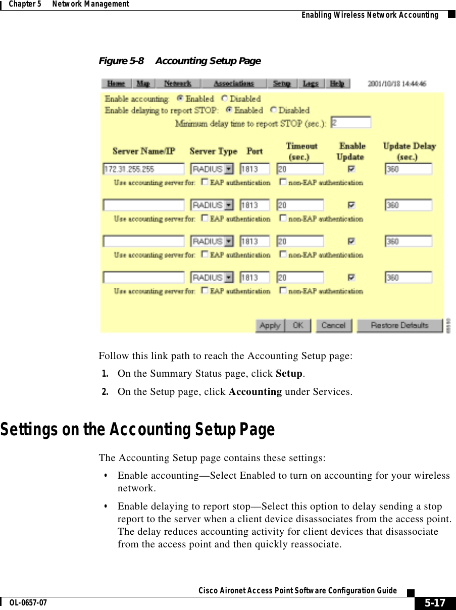

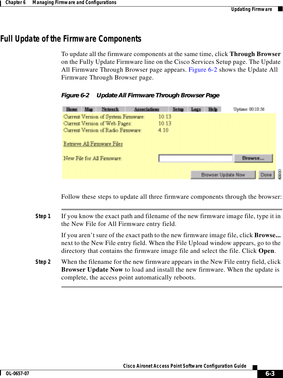
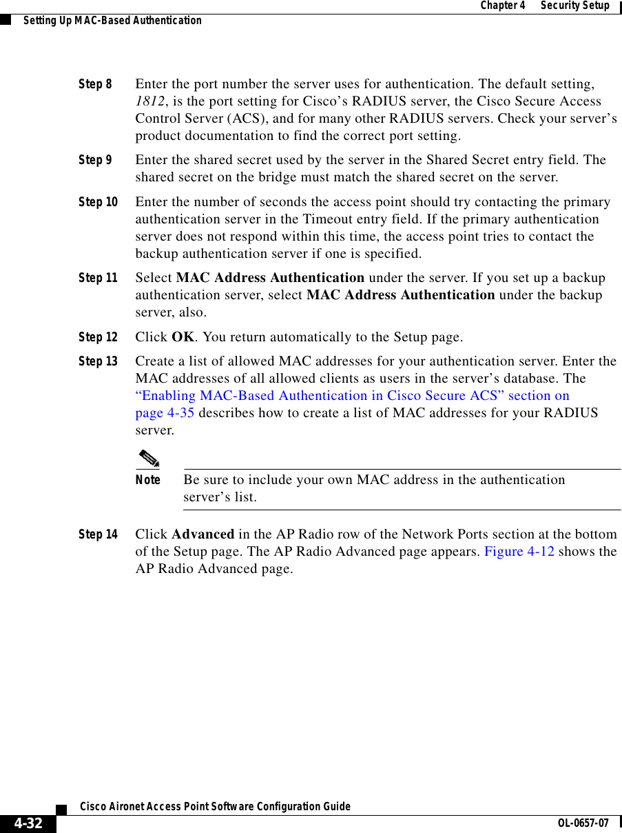
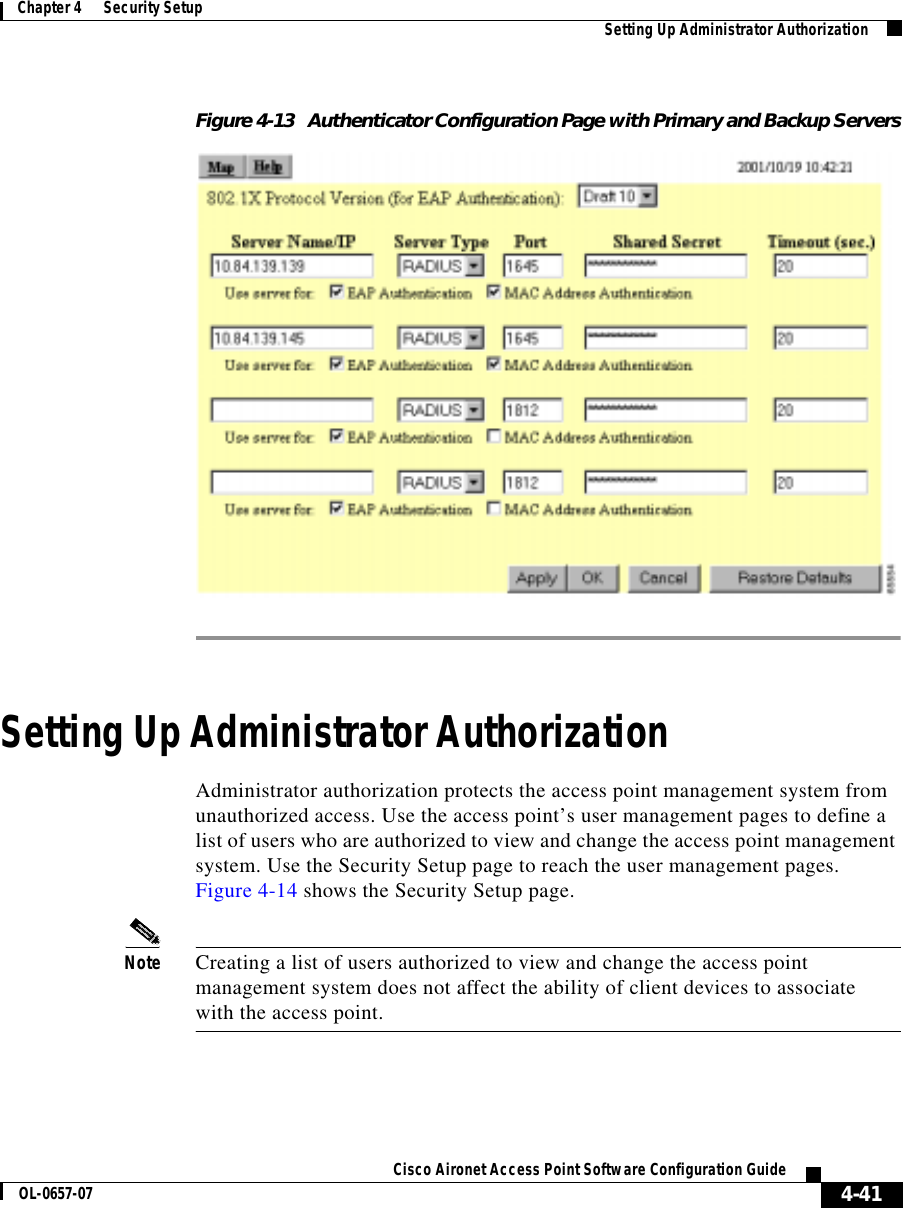
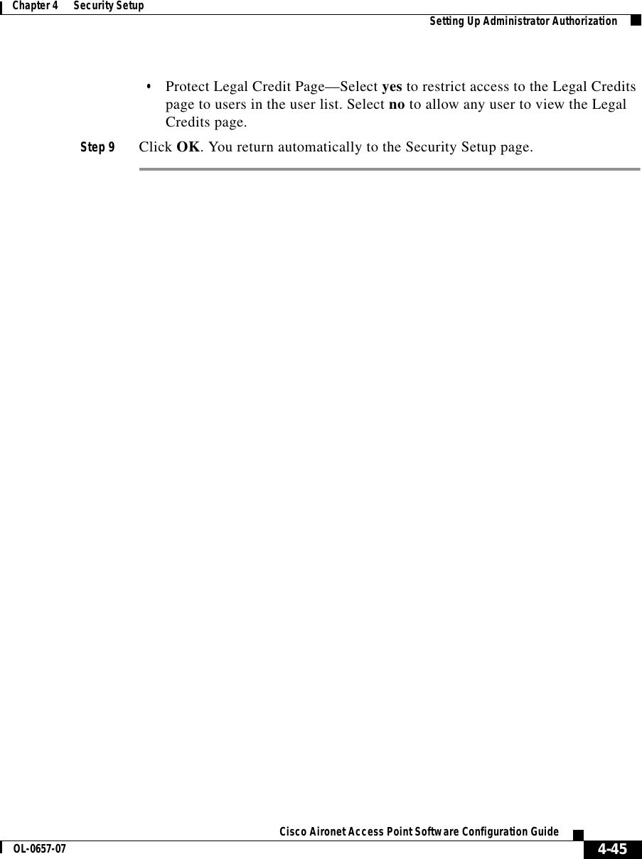
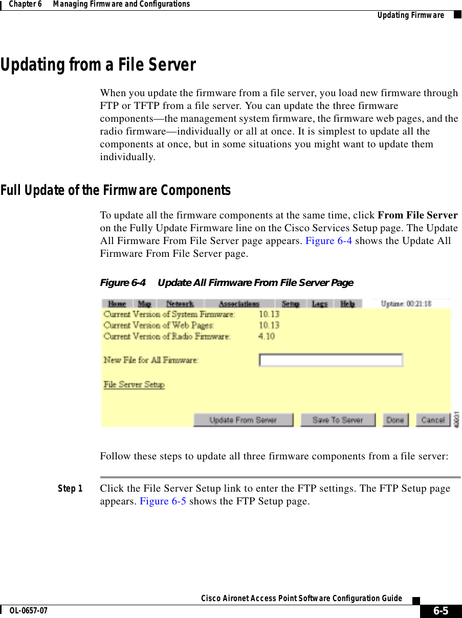
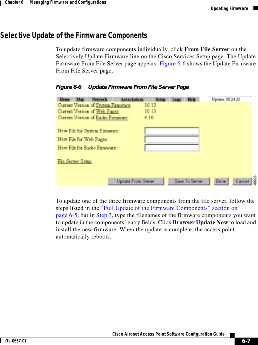
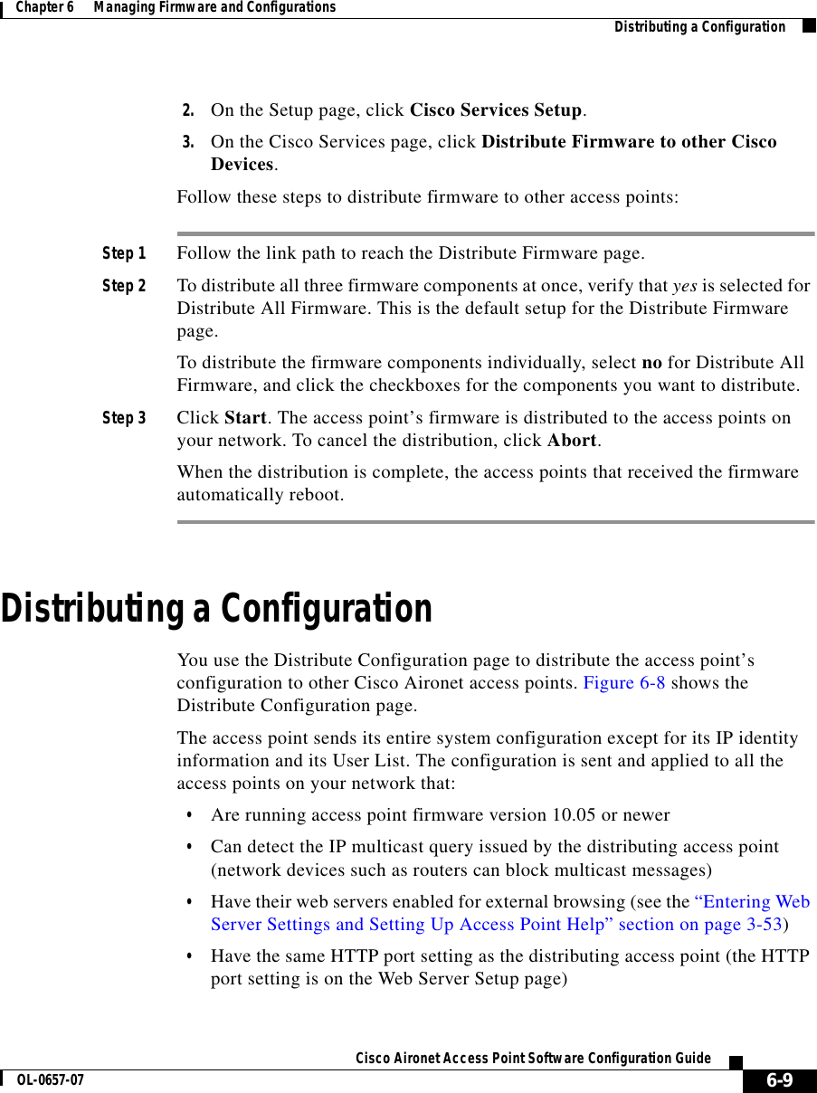
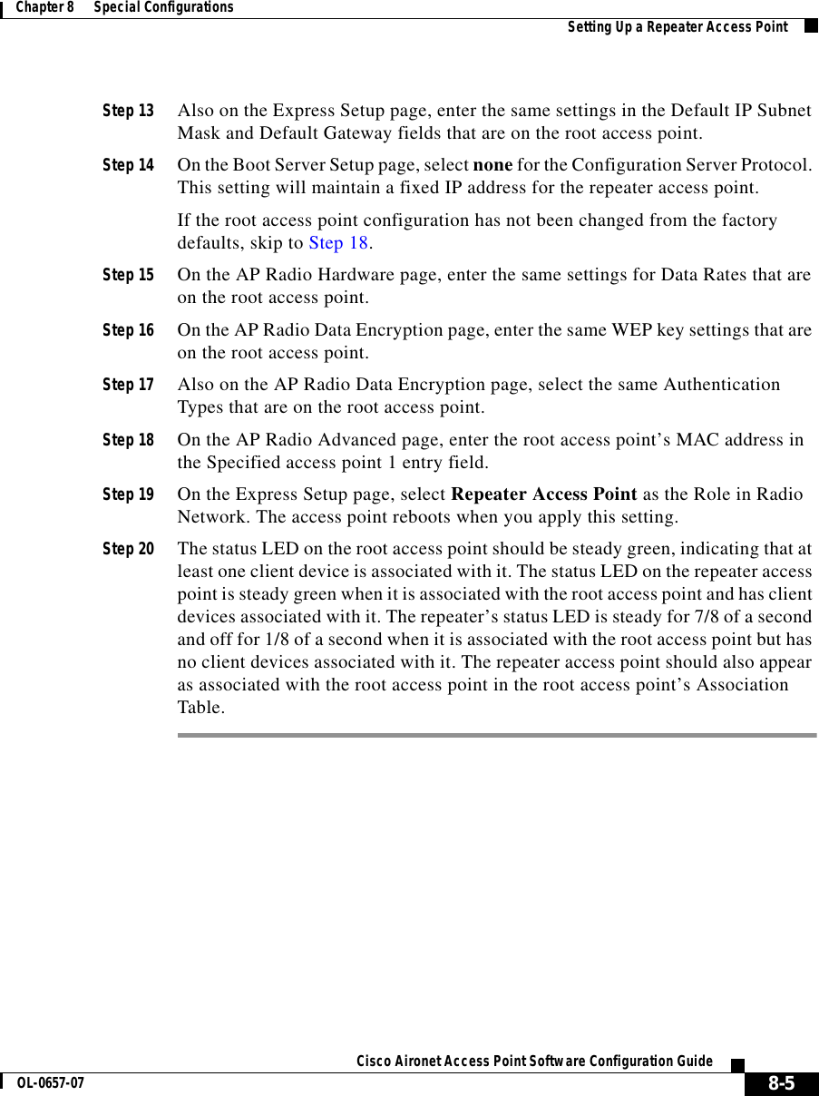
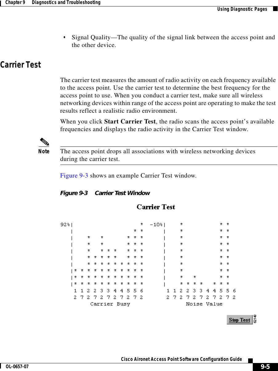
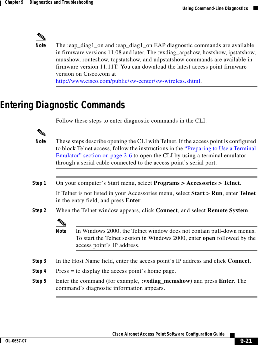
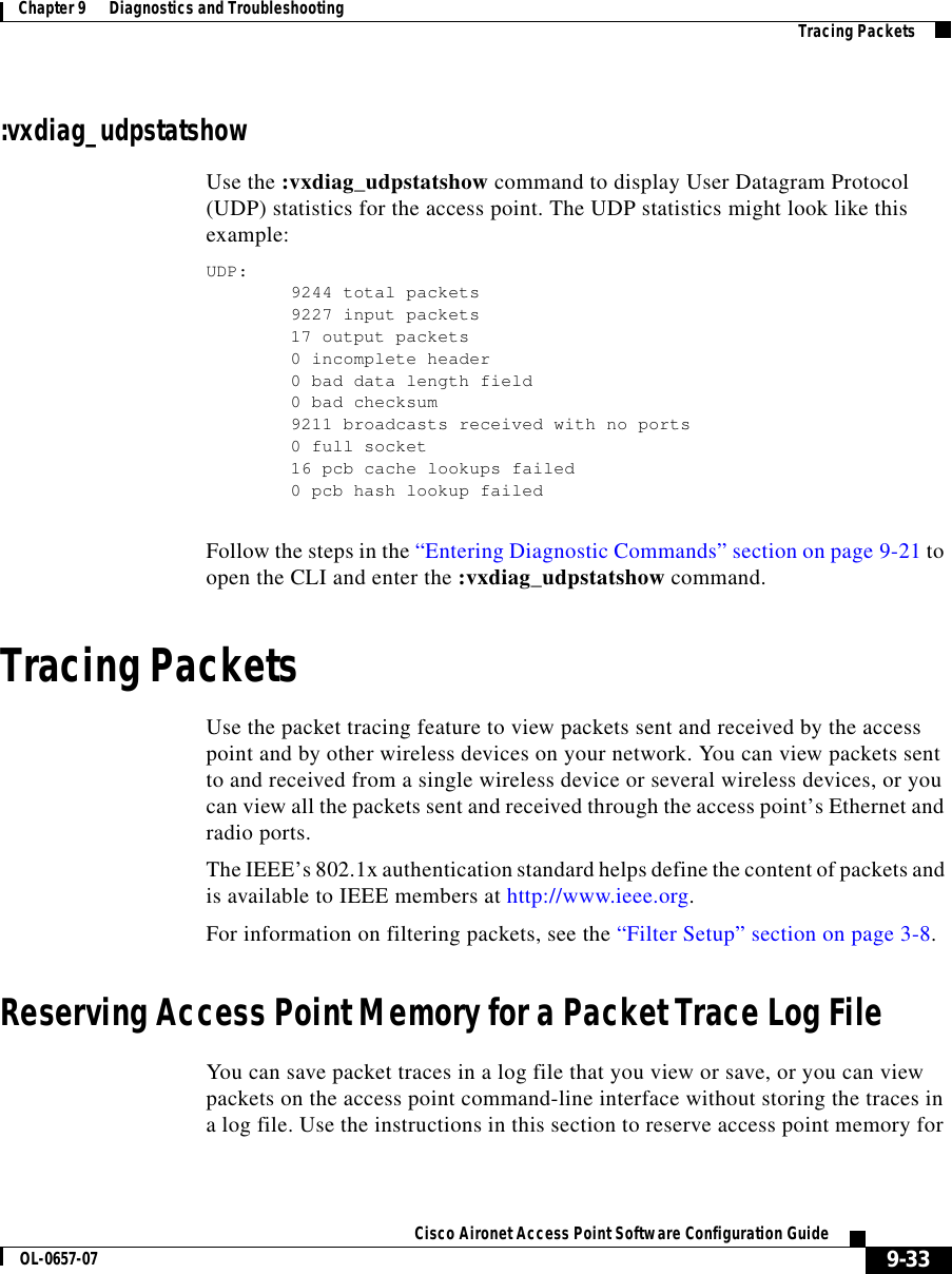
![Chapter 6 Managing Firmware and ConfigurationsUpdating Firmware6-4Cisco Aironet Access Point Software Configuration Guide OL-0657-07Selective Update of the Firmware ComponentsTo update firmware components individually, click Through Browser on the Selectively Update Firmware line on the Cisco Services Setup page. The Update Firmware Through Browser page appears. Figure 6-3 shows the Update Firmware Through Browser page.Figure 6-3 Update Firmware Through Browser PageFollow these steps to update one of the three firmware components through the browser:Step 1 If you know the exact path and filename of the new firmware component, type it in the New File for [component] entry field.If you aren’t sure of the exact path to the new component, click Browse... next to the component’s New File entry field. When the File Upload window appears, go to the directory that contains the component and select the file. Click Open.Step 2 When the filename for the new component appears in the New File entry field, click Browser Update Now to load and install the new component. When the update is complete, the AP automatically reboots.](https://usermanual.wiki/VPN-Systems/VPN350.Correspondence-24174-Question-1-Users-Manual-Section-2/User-Guide-281317-Page-42.png)
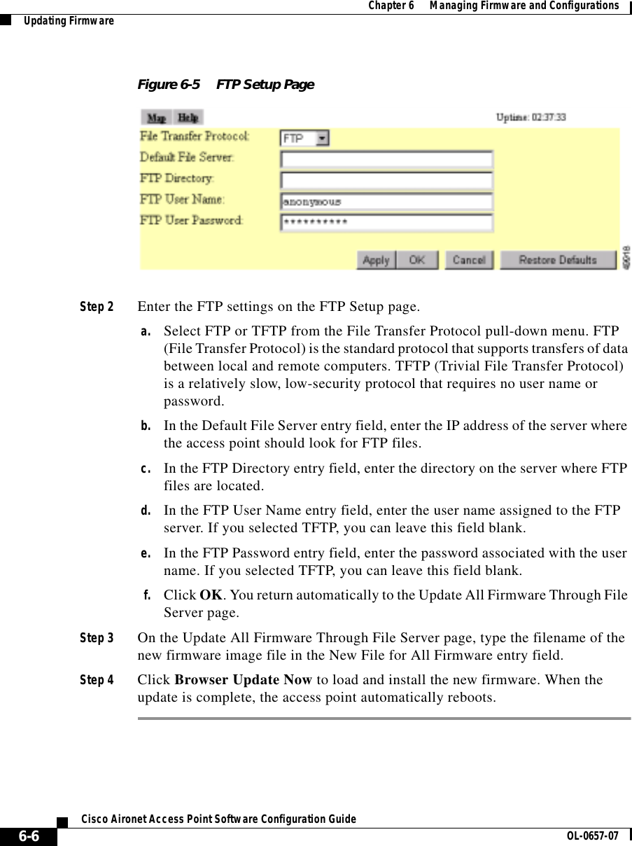
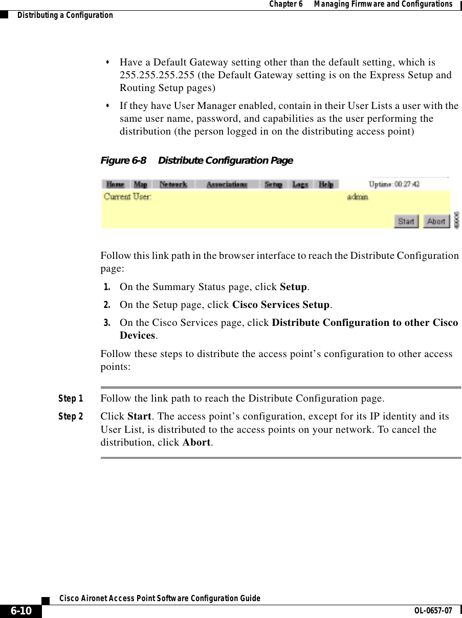
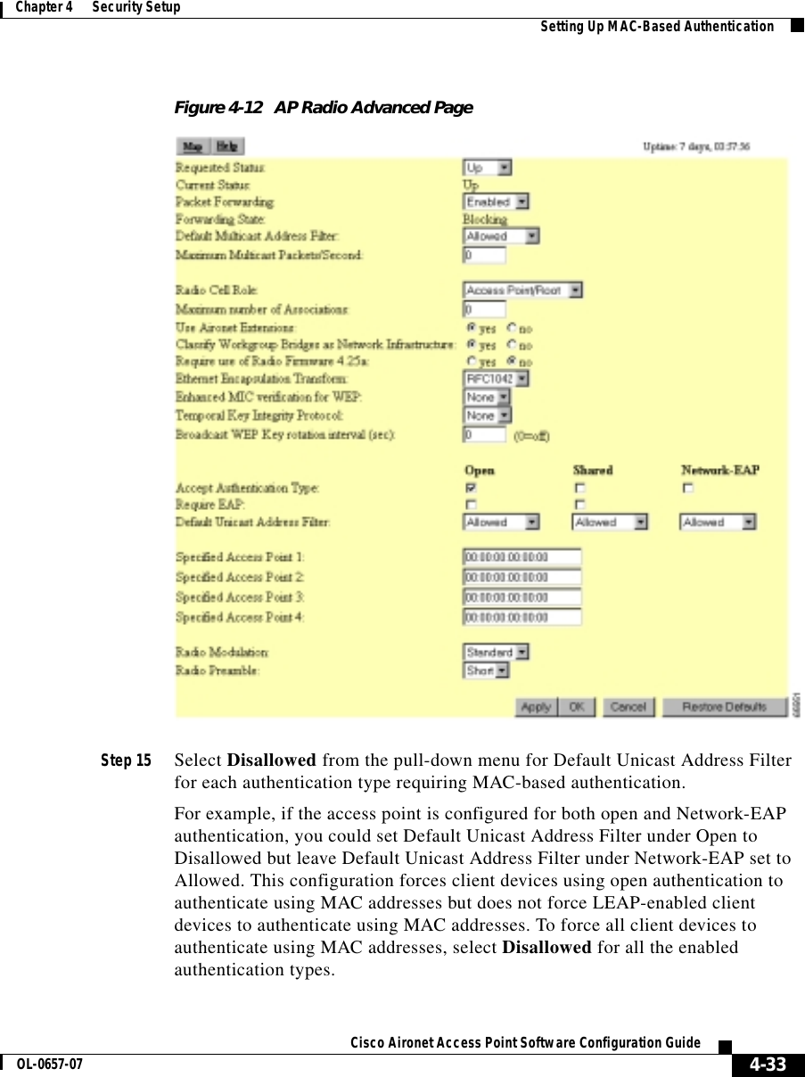
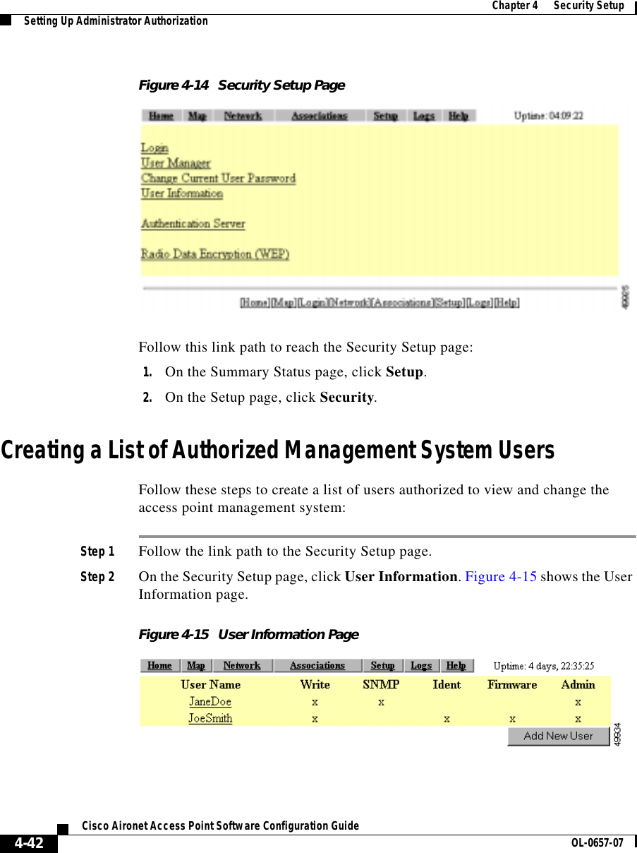
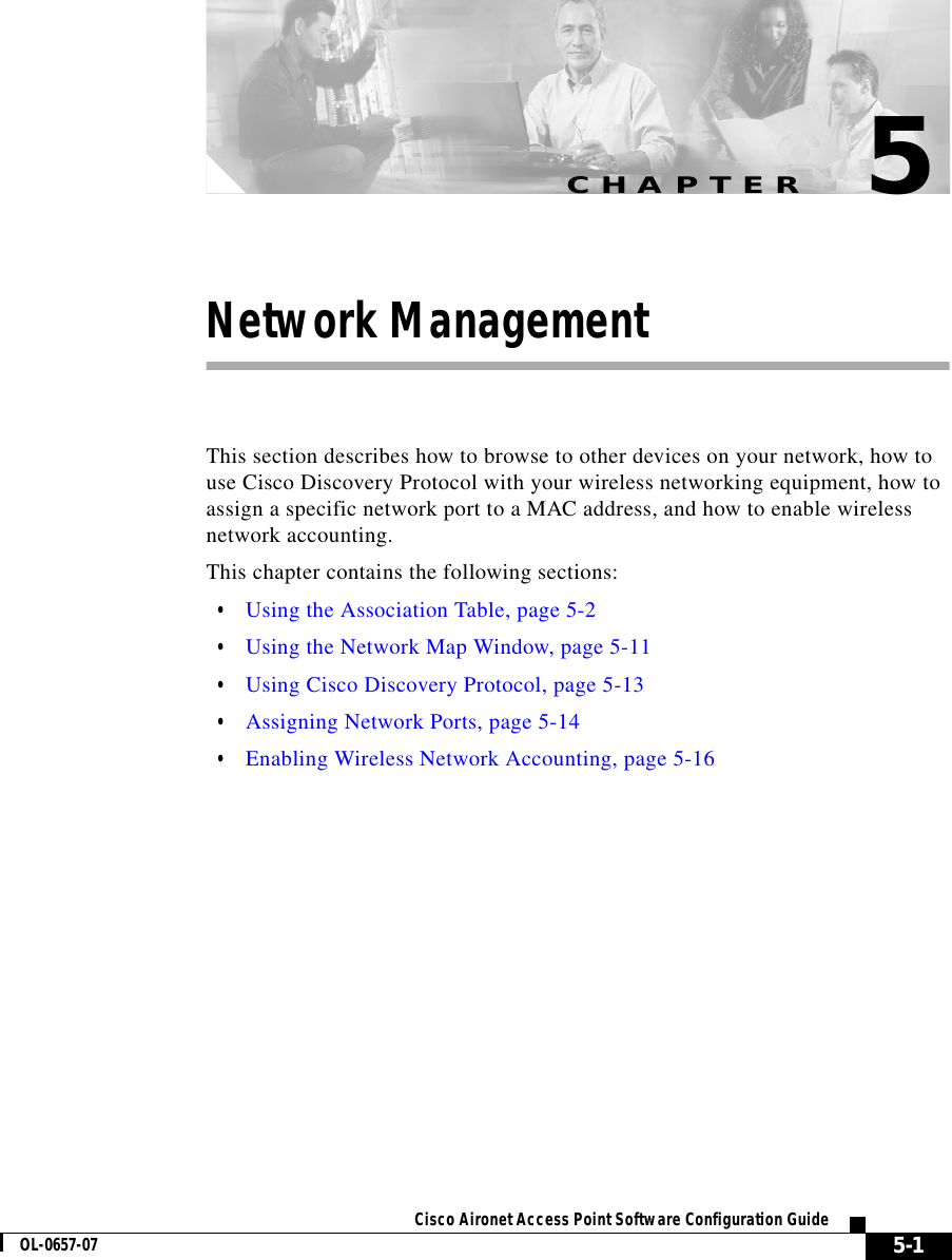
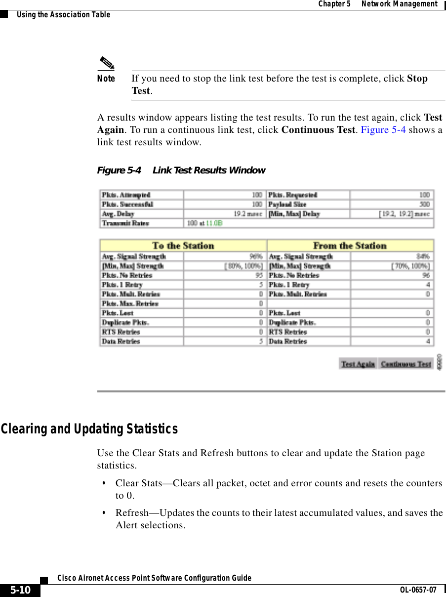
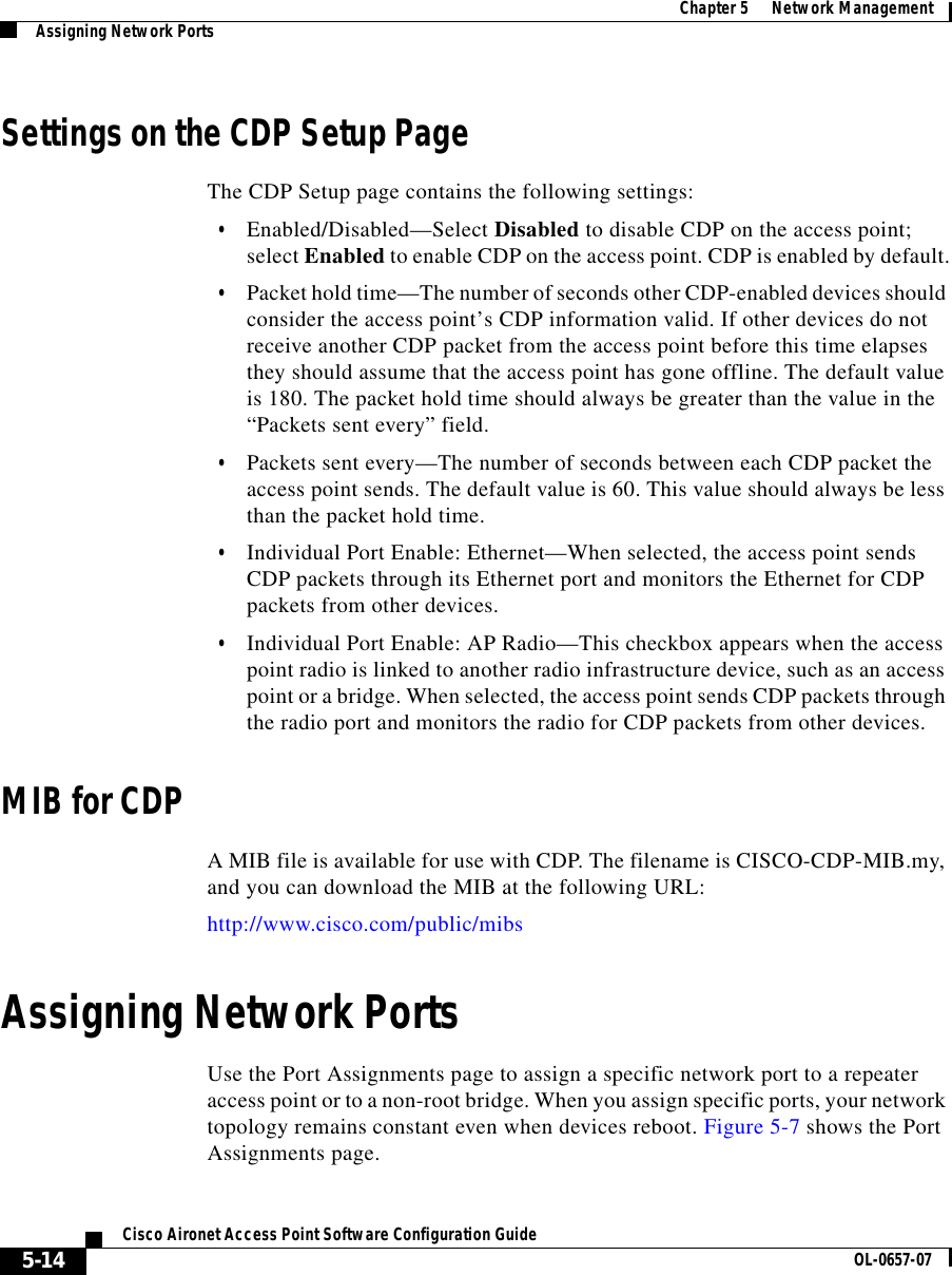
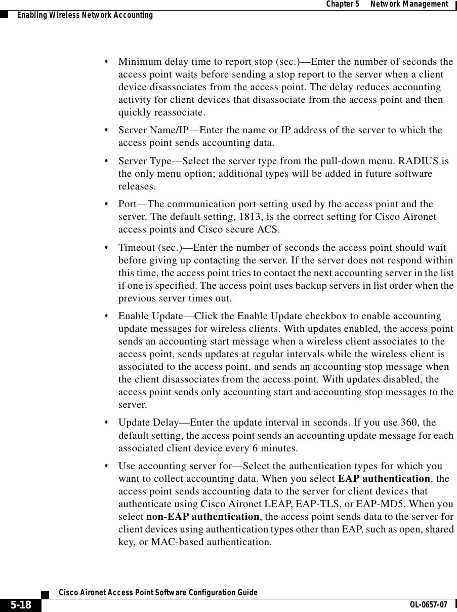
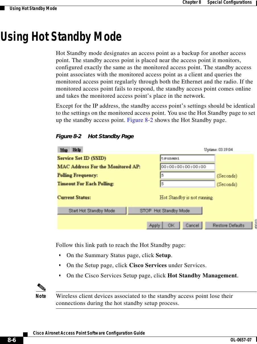
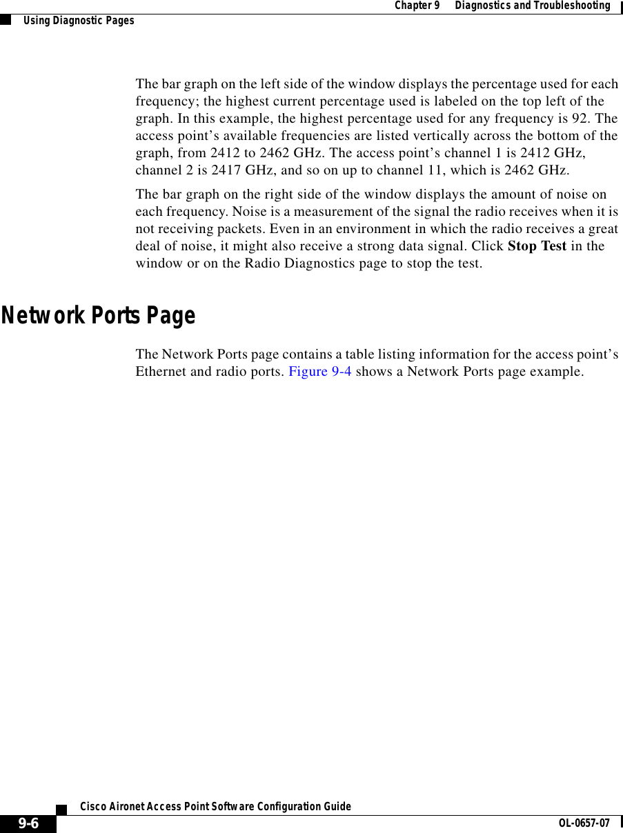
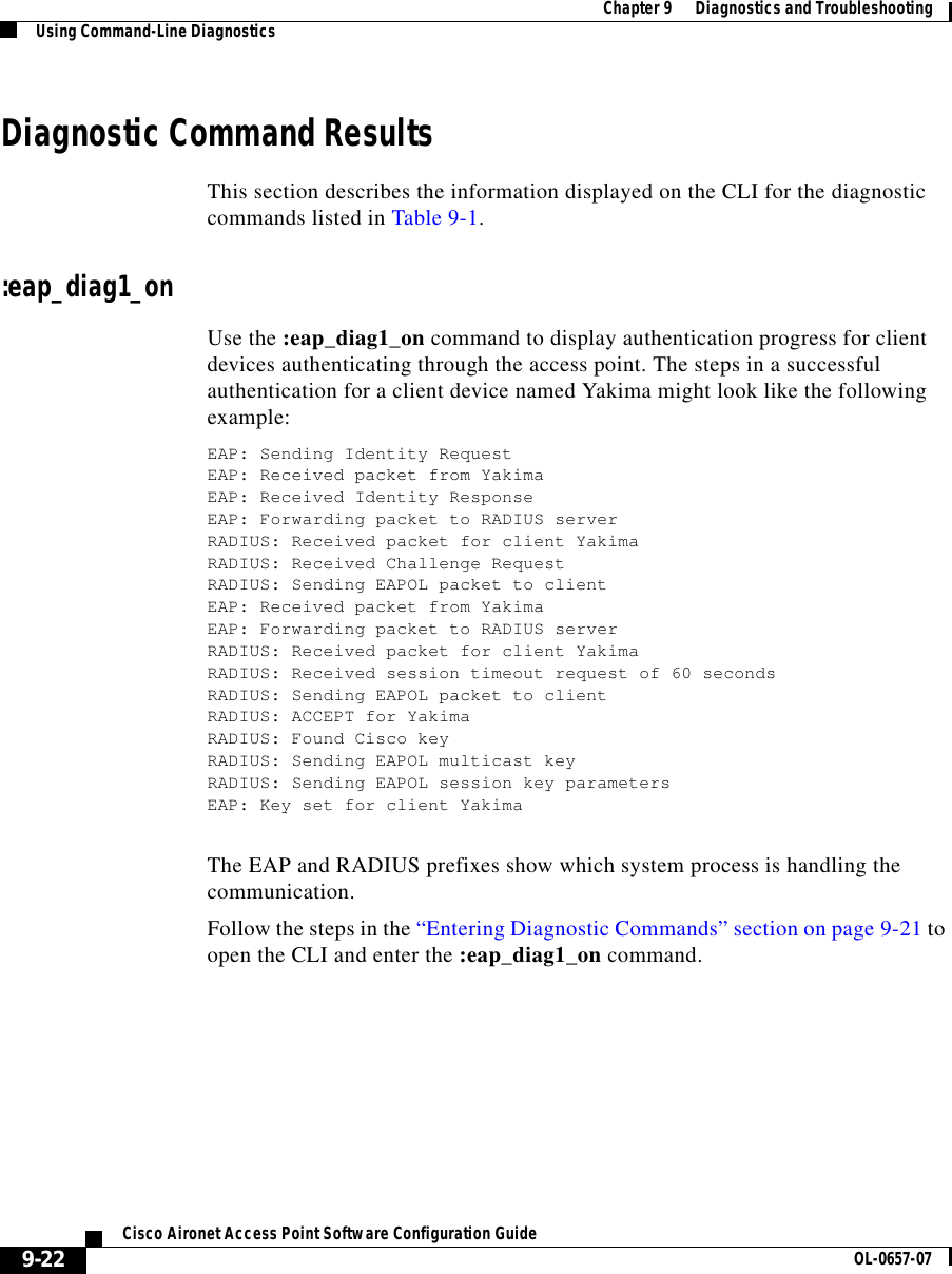
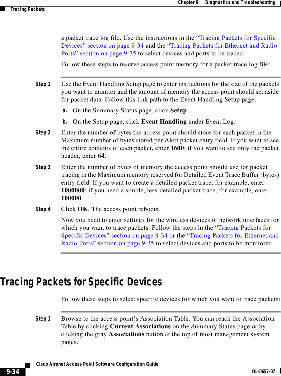
![Chapter 6 Managing Firmware and ConfigurationsDownloading, Uploading, and Resetting the Configuration6-14Cisco Aironet Access Point Software Configuration Guide OL-0657-07Figure 6-10 FTP Setup PageStep 2 Enter the FTP settings on the FTP Setup page.a. Select FTP or TFTP from the File Transfer Protocol pull-down menu. FTP (File Transfer Protocol) is the standard protocol that supports transfers of data between local and remote computers. TFTP (Trivial File Transfer Protocol) is a relatively slow, low-security protocol that requires no user name or password.b. In the Default File Server entry field, enter the IP address of the server where the access point should look for FTP files.c. In the FTP Directory entry field, enter the directory on the server where FTP files are located.d. In the FTP User Name entry field, enter the user name assigned to the FTP server. If you selected TFTP, you can leave this field blank.e. In the FTP Password entry field, enter the password associated with the user name. If you selected TFTP, you can leave this field blank.f. Click OK. You return automatically to the Setup page.Step 3 Follow the link path in the web browser to reach the System Configuration Setup page.Step 4 Click Read Config File From Server. The management system checks the server for several possible configuration filenames while attempting to load the configuration file. If the management system doesn’t find the first filename, it continues to the next until it finds the file and loads it. It checks the server for the following names in the following order:a. [system name].ini](https://usermanual.wiki/VPN-Systems/VPN350.Correspondence-24174-Question-1-Users-Manual-Section-2/User-Guide-281317-Page-52.png)
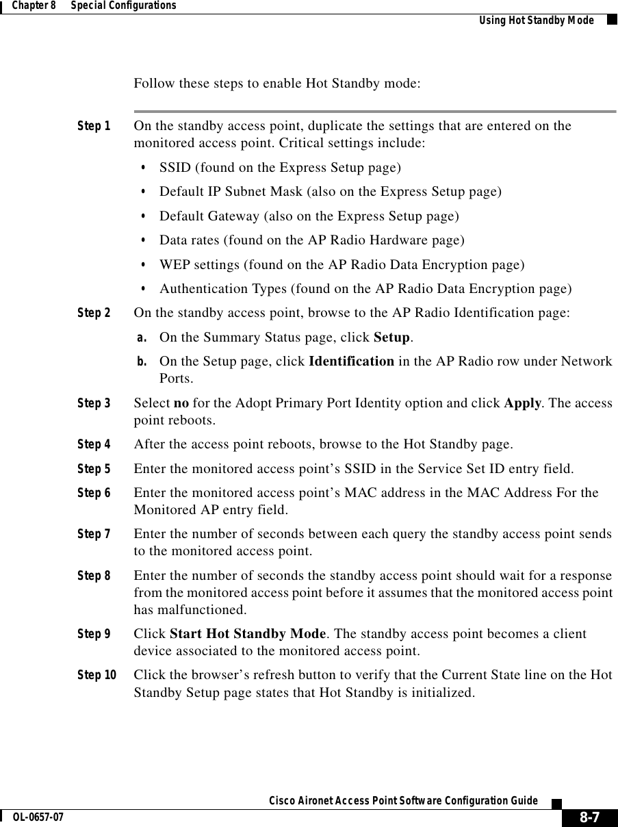
![6-15Cisco Aironet Access Point Software Configuration GuideOL-0657-07Chapter 6 Managing Firmware and Configurations Downloading, Uploading, and Resetting the Configurationb. [IP address].inic. [boot file from DHCP/BOOTP server].inid. [boot file from DHCP/BOOTP server].ini by TFTPResetting the ConfigurationYou can reset the access point configuration to the default settings without resetting the access point’s IP identity, or you can reset the configuration to the default settings including the IP identity. If you reset the access point’s IP identity, however, you might lose your browser connection to the access point.Two buttons on the System Configuration Setup page reset the configuration to defaults:•Reset System Factory Defaults Except IP Identity—this button returns all access point settings to their factory defaults except: –The access point’s IP address, subnet mask, default gateway, and boot protocol–The users in the User Manager list –The SNMP Administrator Community name•Reset All System Factory Defaults—this button returns all access point settings to their factory defaults except: –The users in the User Manager list –The SNMP Administrator Community nameNote To completely reset all access point settings to defaults, follow the steps in the “Resetting to the Default Configuration” section on page 9-44.Follow these steps to reset the configuration to default settings:Step 1 Follow the link path to reach the System Configuration Setup page. Figure 6-9 shows the System Configuration Setup page. The link path is listed under Figure 5-9.](https://usermanual.wiki/VPN-Systems/VPN350.Correspondence-24174-Question-1-Users-Manual-Section-2/User-Guide-281317-Page-53.png)
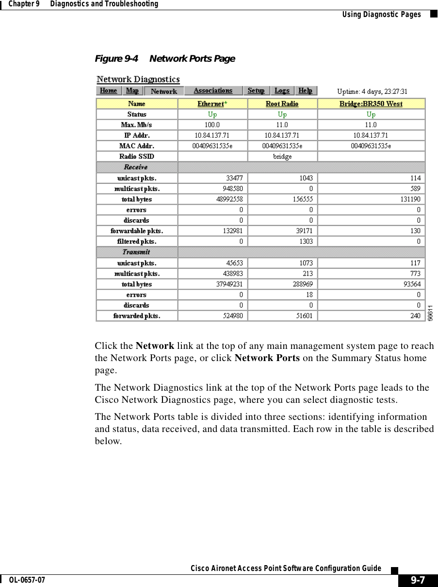
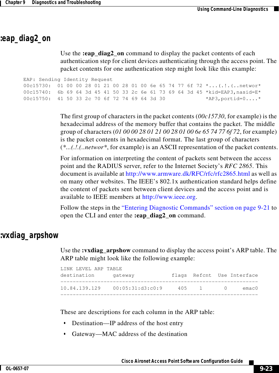
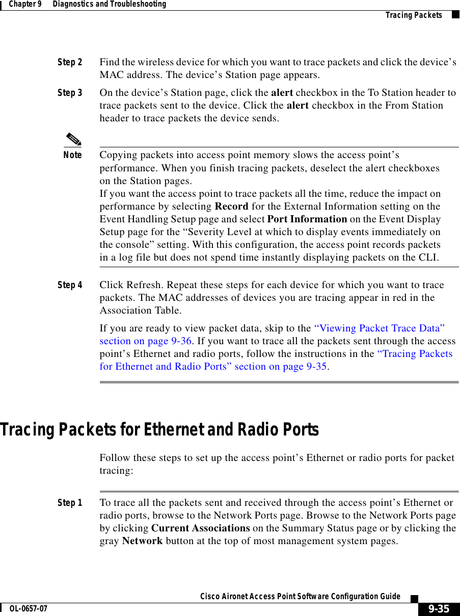
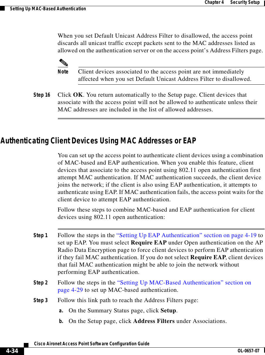
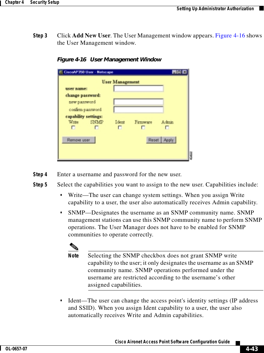
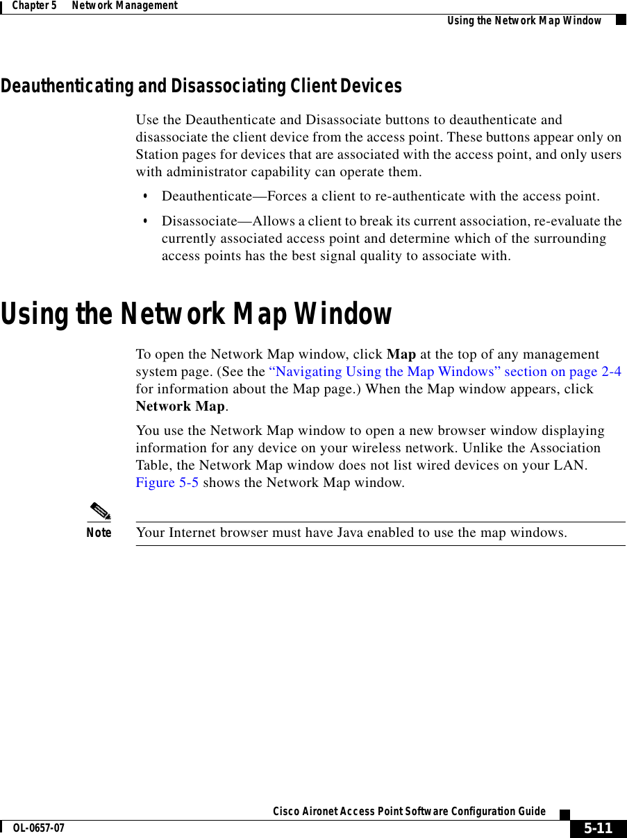
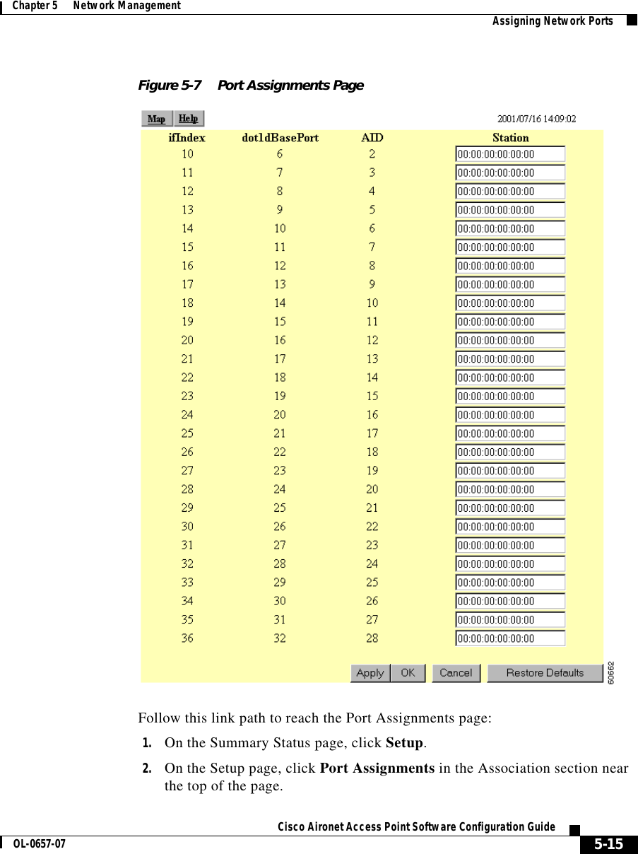
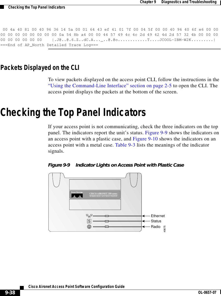
![9-37Cisco Aironet Access Point Software Configuration GuideOL-0657-07Chapter 9 Diagnostics and Troubleshooting Tracing PacketsPackets Stored in a Log FileFollow these steps to view traced packets stored in a log file:Step 1 Browse to the Event Handling Setup page. Follow this link path to the Event Handling Setup page:a. On the Summary Status page, click Setup.b. On the Setup page, click Event Handling under Event Log.Step 2 Click Headers Only to view only the packet headers; click All Data to view all the collected packet information.Step 3 A File Download window appears asking if you want to save the [access point name]_trace.log file or open it. Choose to save or open the file and click OK. A portion of the Headers Only packet trace file might look like this example:===Beginning of AP_North Detailed Trace Log===04:46:14 +17174.384615 Station Alert: 00:01:64:43:ef:41Aironet:40:6f:e6Aironet:40:6f:e60x000004:47:37 + 83.326923 Station Alert: 00:01:64:43:ef:41Aironet:40:6f:e6Aironet:36:14:5a0x000004:49:06 + 88.307692 Station Alert: 00:01:64:43:ef:41Aironet:40:6f:e6broadcastARP04:49:06 + 0.000000 Station Alert: 00:05:31:d3:c0:0900:01:64:43:ef:41ARP04:49:06 + 0.000000 Station Alert: 00:01:64:43:ef:41Aironet:40:6f:e600:05:31:d3:c0:09IPIPv4 UDP ID=0x14f2 totalLen=96 10.84.139.164 -> ne-wins.cisco.com04:49:06 + 0.230769 Station Alert: 00:05:31:d3:c0:0900:01:64:43:ef:41IP IPv4 UDPID=0xb0b4 totalLen=90 ne-wins.cisco.com -> 10.84.139.16404:49:06 + 0.019231 Station Alert: 00:01:64:43:ef:41Aironet:40:6f:e600:05:31:d3:c0:09IPIPv4 UDP ID=0x14f3 totalLen=96 10.84.139.164 -> ne-wins.cisco.com04:49:06 + 0.192308 Station Alert: 00:05:31:d3:c0:0900:01:64:43:ef:41IP IPv4 UDPID=0xb2b4 totalLen=90 ne-wins.cisco.com -> 10.84.139.164===End of AP_North Detailed Trace Log===A portion of the All Data packet trace file might look like this example:===Beginning of AP_North Detailed Trace Log===04:46:14 +17174.384615 Station Alert:00:01:64:43:ef:41[Aironet]00:40:96:40:6f:e6[Aironet]00:40:96:40:6f:e6 0x000000 4a 40 81 00 40 96 40 6f e6 00 01 64 43 ef 41 01 7f 00 04 5f 00 00 40 96 40 6f e6 00 0000 00 00 00 00 00 00 00 0a 54 8b a4 00 00 44 57 49 4c 4c 2d 49 42 4d 2d 57 32 4b 00 00 0000 00 00 00 00 00 |.J@..@.@o...dC.A..._..@.@o............T....JCOOL-IBM-W2K.........|04:47:37 + 83.326923 Station Alert:00:01:64:43:ef:41[Aironet]00:40:96:40:6f:e6[Aironet]00:40:96:36:14:5a 0x0000](https://usermanual.wiki/VPN-Systems/VPN350.Correspondence-24174-Question-1-Users-Manual-Section-2/User-Guide-281317-Page-105.png)
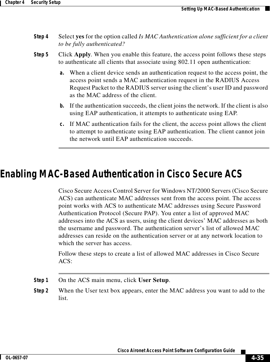
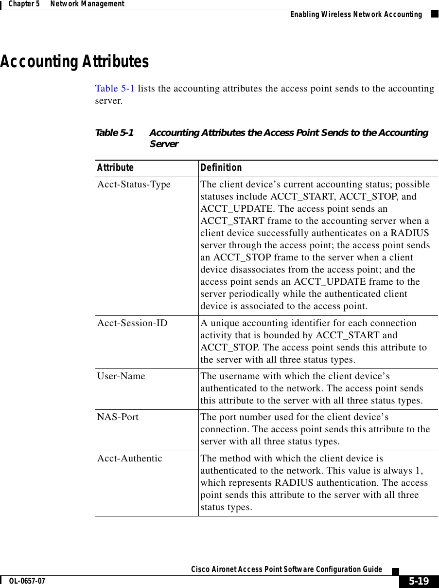
![Chapter 9 Diagnostics and TroubleshootingResetting to the Default Configuration9-46Cisco Aironet Access Point Software Configuration Guide OL-0657-07Steps for Firmware Versions 11.06 or EarlierFollow the steps in this section if your access point is running firmware version 11.06 or earlier.Note The following steps reset all configuration settings to factory defaults, including passwords, WEP keys, the IP address, and the SSID. If you do not need to reset the entire configuration, use the Configuration Reset buttons on the System Configuration Setup page in the web-browser interface. Consult the “Resetting the Configuration” section on page 6-15 for more information on the reset buttons in the web-browser interface.Determining the Boot-Block VersionThe steps you follow to reconfigure the access point depend on the version of the access point’s boot block. Follow these steps to find out which boot block version is on your access point:Step 1 Open a Telnet session to the access point.Note You can also use these instructions while communicating with the access point through the console port or with an SNMP manager. Skip to Step 3 if you use an SNMP manager.Step 2 Type :cmd and press Enter to switch from text-browser mode to SNMP mode.Step 3 Type bootblockVersion and press Enter. Text appears with information about the system. If your access point’s boot block version is 1.01, the text might look like this:OID: iso.org.dod.internet.private.enterprises.aironet.awcVx.awcSystem.bootblockVersionValue [RO]: 1.01Step 4 Type exit and press Enter to return to text-browser mode.](https://usermanual.wiki/VPN-Systems/VPN350.Correspondence-24174-Question-1-Users-Manual-Section-2/User-Guide-281317-Page-114.png)
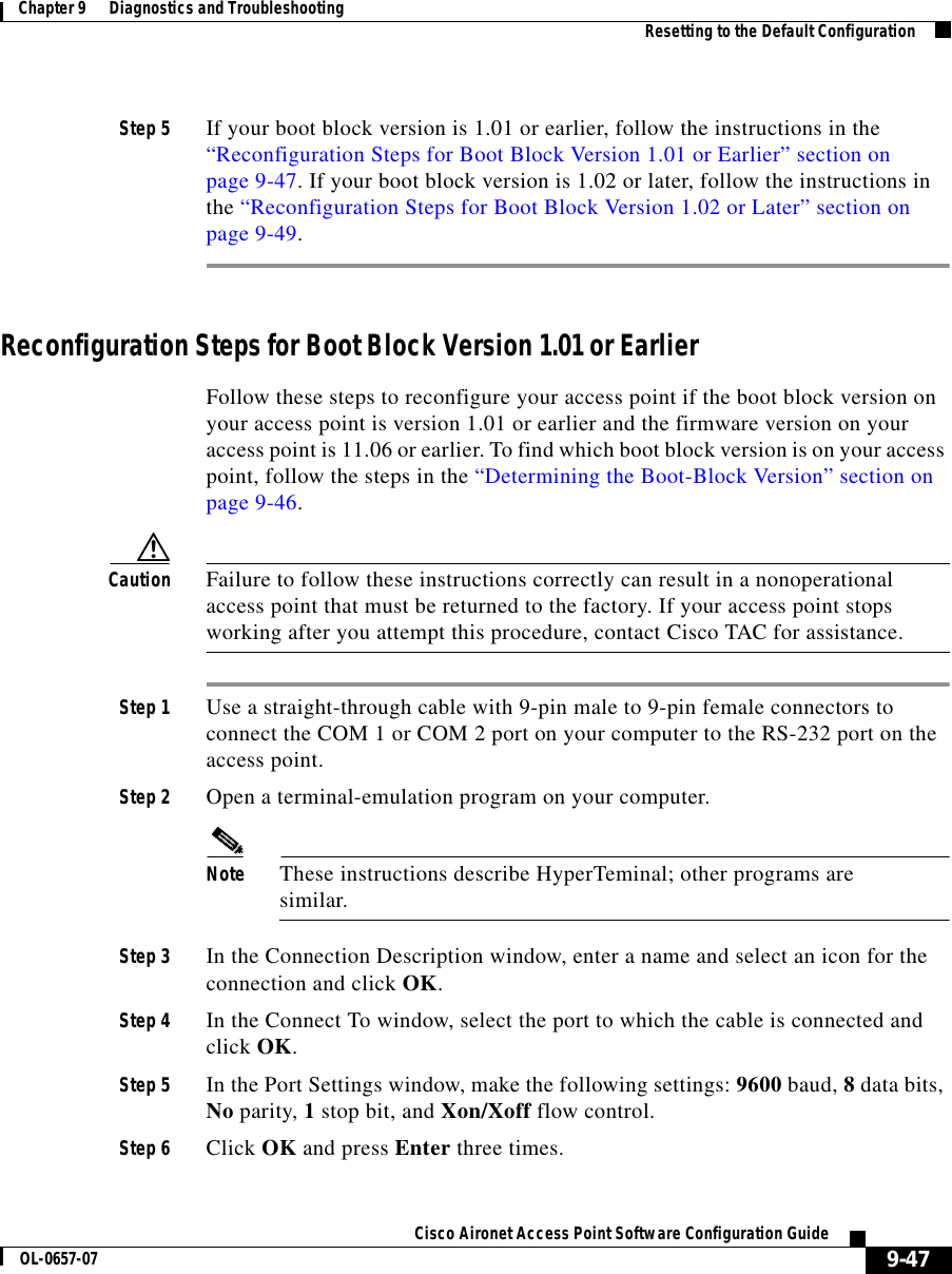
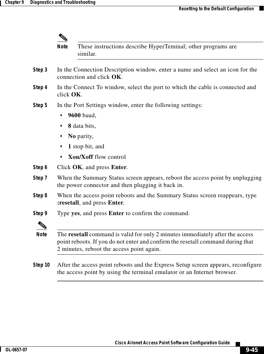
![9-49Cisco Aironet Access Point Software Configuration GuideOL-0657-07Chapter 9 Diagnostics and Troubleshooting Resetting to the Default ConfigurationStep 15 Run the access point firmware by pressing r to select Run, then the selection letter for the firmware file which is displayed. The message “Inflating [firmware file name]” appears while the access point starts the firmware.Step 16 When the Express Setup screen appears, begin reconfiguring the access point using the terminal emulator or an Internet browser.Reconfiguration Steps for Boot Block Version 1.02 or LaterFollow these steps to reconfigure your access point if the boot block version on your access point is version 1.02 or later and the firmware version on your access point is 11.06 or earlier. To find which boot block version is on your access point, follow the steps in the “Determining the Boot-Block Version” section on page 9-46.Caution Failure to follow these instructions correctly can result in a nonoperational access point that must be returned to the factory. If your access point stops working after you attempt this procedure, contact Cisco TAC for assistance.Step 1 Use a straight-through cable with 9-pin male to 9-pin female connectors to connect the COM 1 or COM 2 port on your computer to the RS-232 port on the access point.Step 2 Open a terminal-emulation program on your computer.Note These instructions describe HyperTeminal; other programs are similar.Step 3 In the Connection Description window, enter a name and select an icon for the connection and click OK. Step 4 In the Connect To window, select the port to which the cable is connected and click OK. Step 5 In the Port Settings window, make the following settings: 9600 baud, 8 data bits, No parity, 1 stop bit, and Xon/Xoff flow control. Step 6 Click OK and press Enter.](https://usermanual.wiki/VPN-Systems/VPN350.Correspondence-24174-Question-1-Users-Manual-Section-2/User-Guide-281317-Page-117.png)
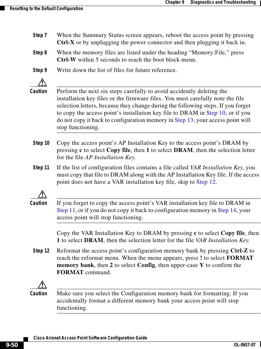
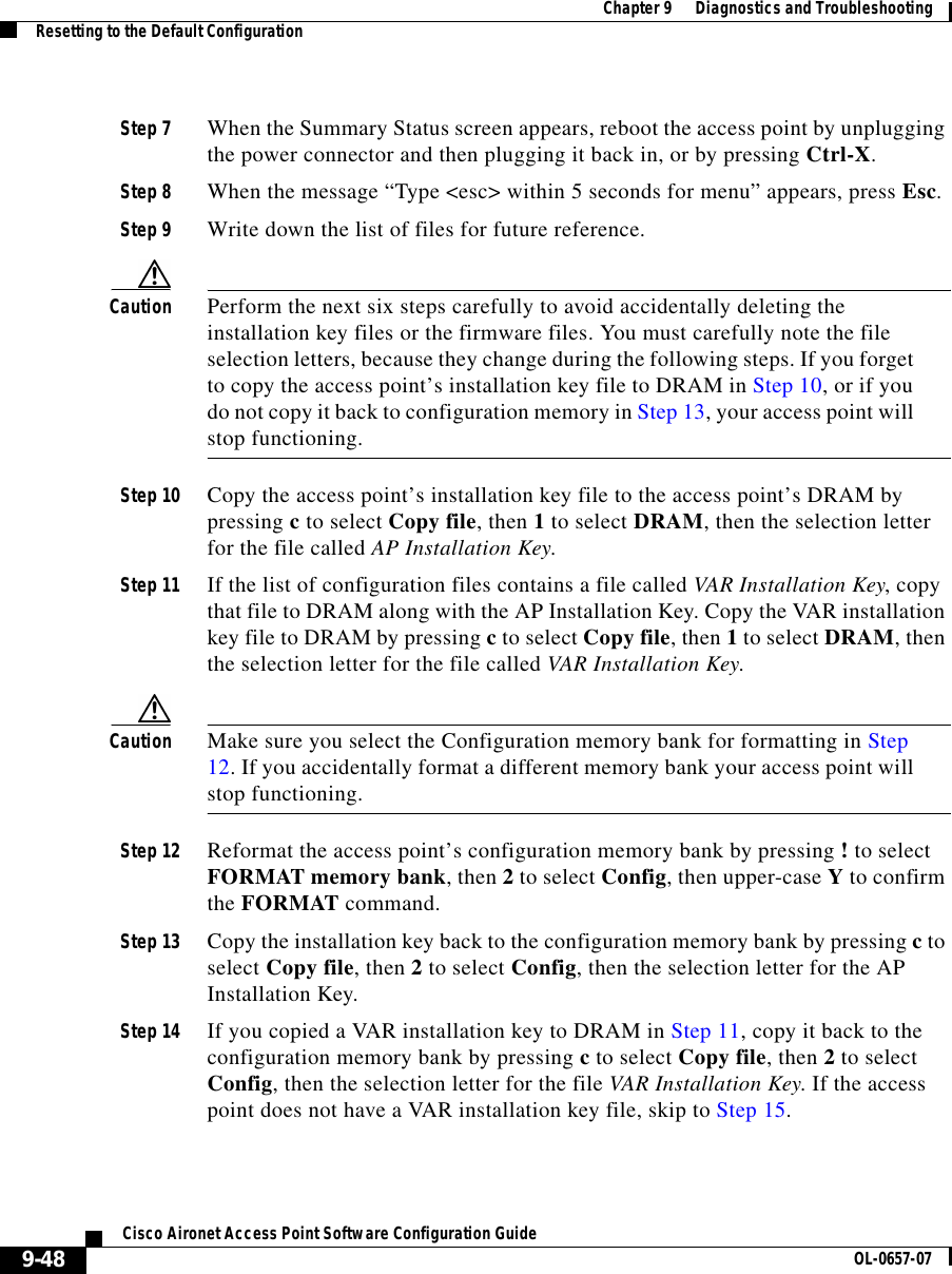
![9-51Cisco Aironet Access Point Software Configuration GuideOL-0657-07Chapter 9 Diagnostics and Troubleshooting Resetting to the Default ConfigurationStep 13 Copy the installation key back to the configuration memory bank by pressing c to select Copy file, then 2 to select Config, then the selection letter for the file AP Installation Key.Step 14 If you copied a VAR installation key to DRAM in Step 11, copy it back to the configuration memory bank by pressing c to select Copy file, then 2 to select Config, then the selection letter for the file VAR Installation Key. If the access point does not have a VAR installation key file, skip to Step 15.Step 15 Run the access point firmware by pressing r to select Run, then the selection letter for the firmware file that is displayed. The message “Inflating [firmware file name]” appears while the access point starts the firmware.Step 16 When the Express Setup screen appears, begin reconfiguring the access point using the terminal emulator or an Internet browser.](https://usermanual.wiki/VPN-Systems/VPN350.Correspondence-24174-Question-1-Users-Manual-Section-2/User-Guide-281317-Page-119.png)