Vertex Standard LMR VZ-30-G6-4 Two Way Radio User Manual VZ 30 G6 4
Vertex Standard LMR, Inc. Two Way Radio VZ 30 G6 4
UserManual.wiki
>
Vertex Standard LMR
>
VZ 30 G6 4 User Manual
user manual
Navigation menu
Upload a User Manual
Namespaces
Wiki Guide
HTML
PDF
Info
Views
User Manual
Discussion / Help
Navigation

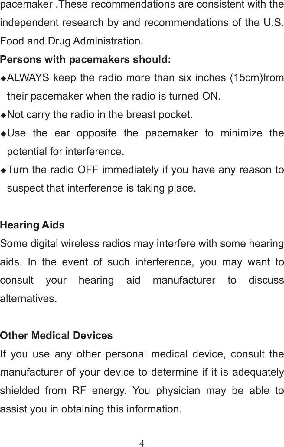
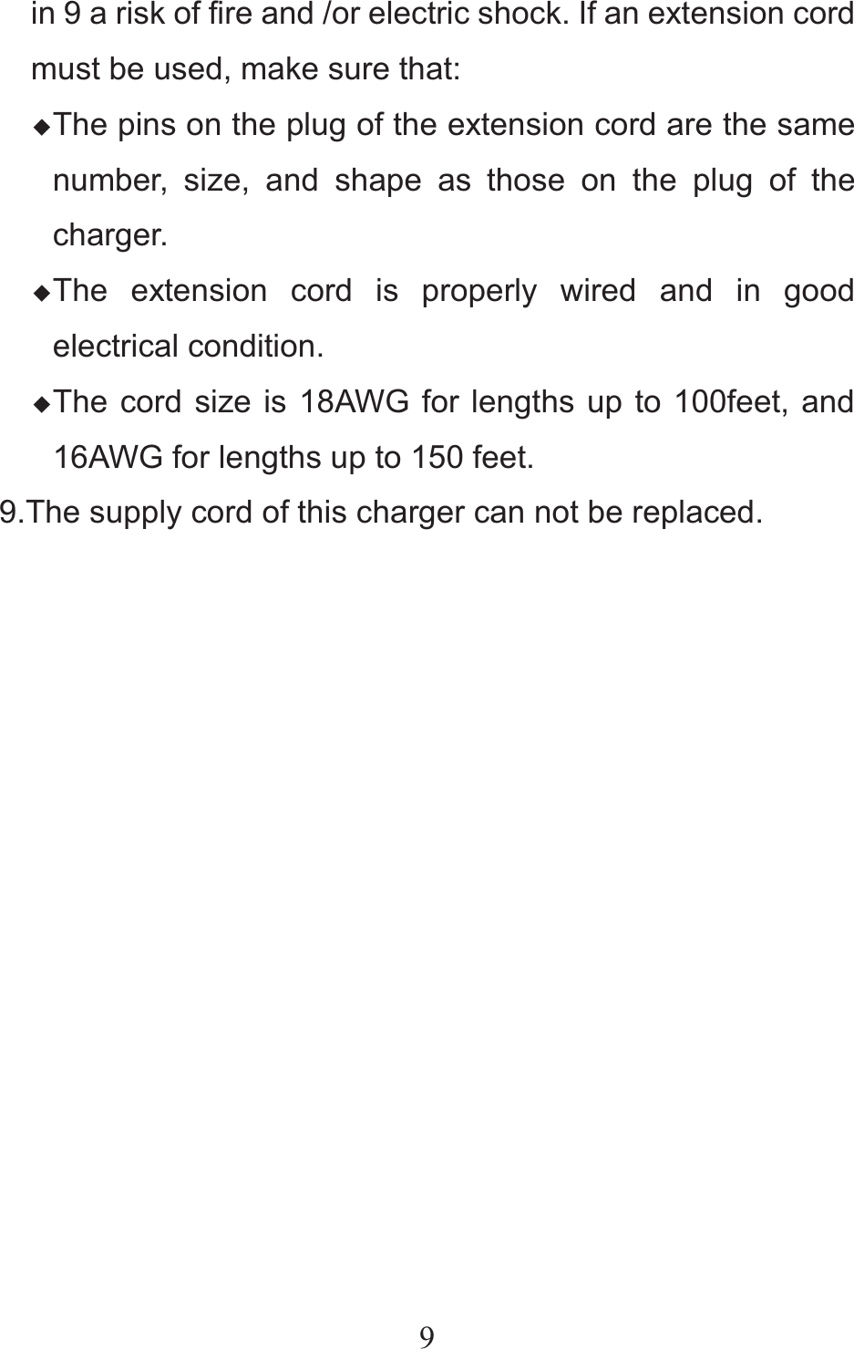
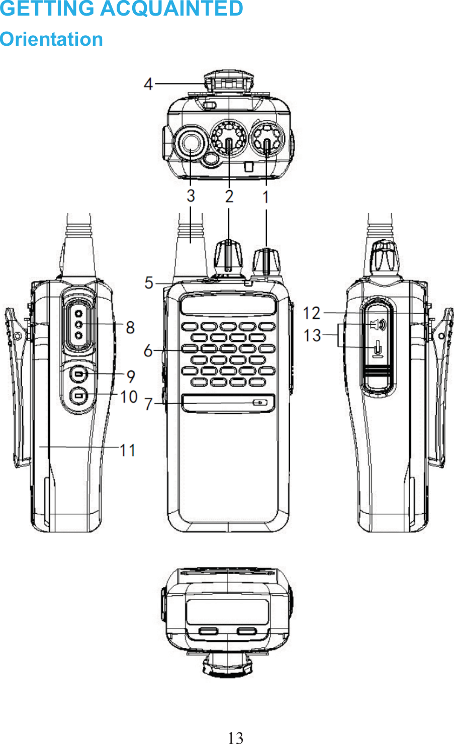
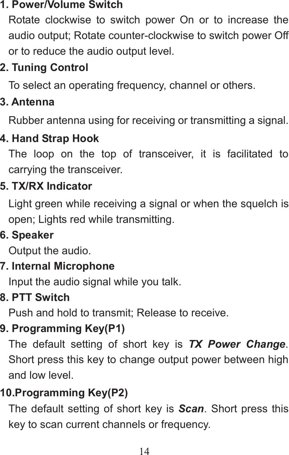
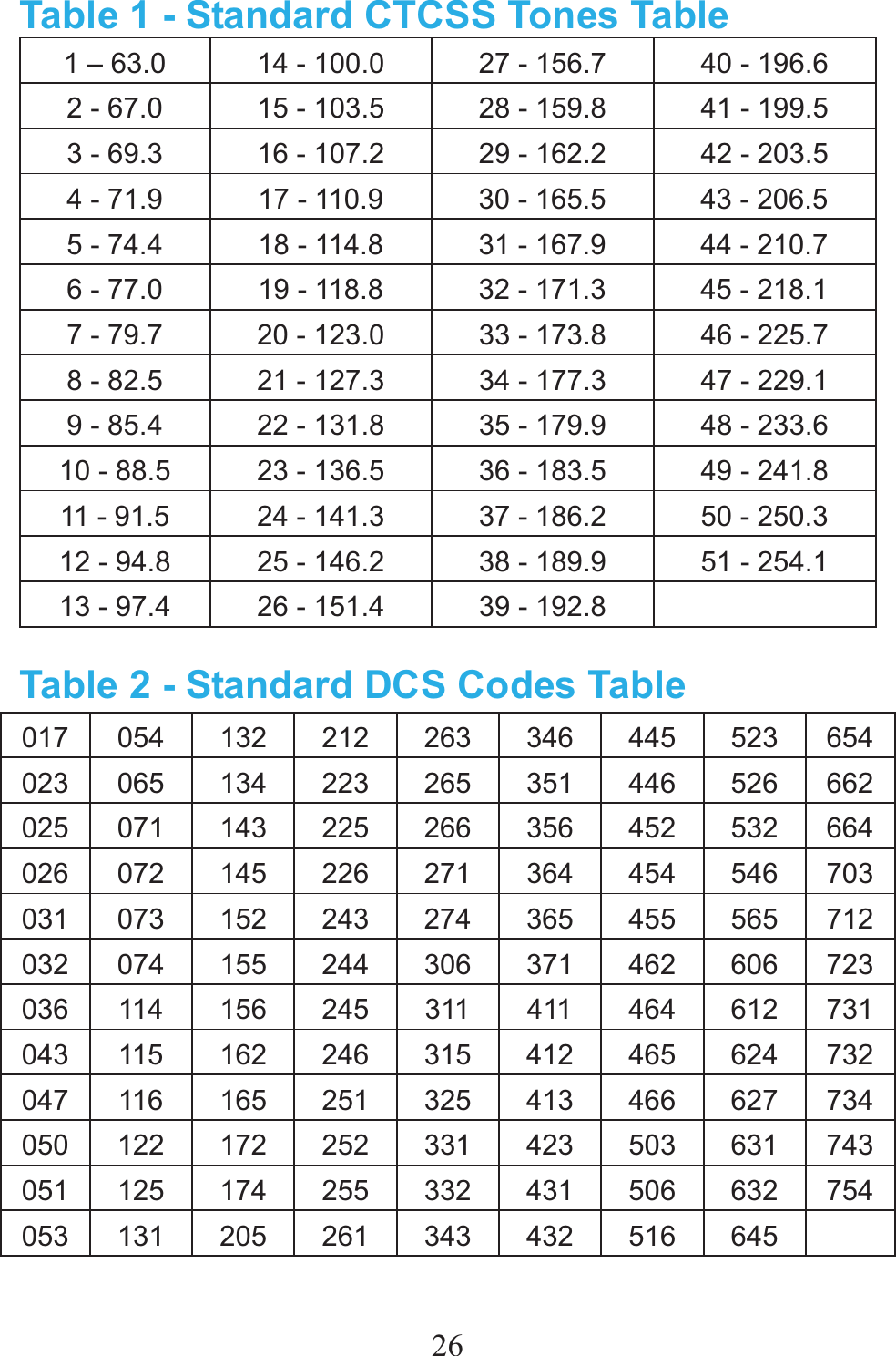
![1511. Battery Pack Supply the power to the transceiver. 12. Battery Lock Button Use to lock/unlock the battery pack. 13. Earphone/Data Cable Jack Connects an earphone or connects a data cable for PC software programming. Programmable Auxiliary Functions Your dealer may program the [P1], [P2] (long press or short press) with one of the following auxiliary functions respectively. No. Function 1 Scan 2 Squelch Off 3 Squelch Off Momentary 4 SQL Change 5 TX Power Change 6 Talk Around 7 VOX Note:You can set the time of pressing long key from 1.5-5 seconds(default: 2.0 seconds) with programming software, when](https://usermanual.wiki/Vertex-Standard-LMR/VZ-30-G6-4/User-Guide-2482134-Page-19.png)
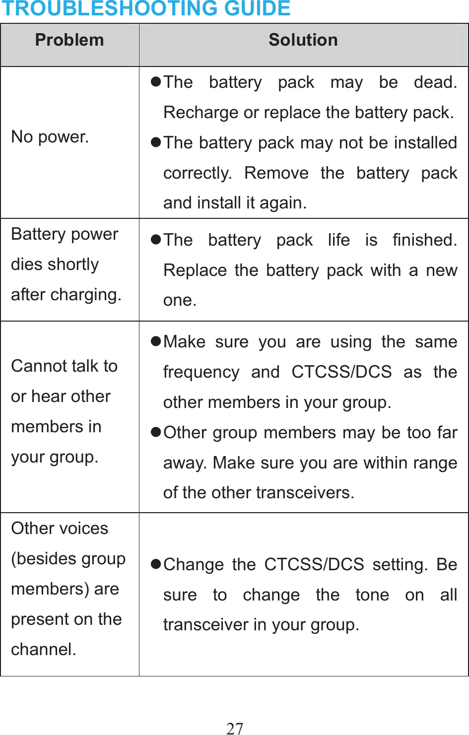
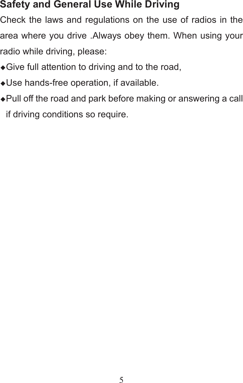
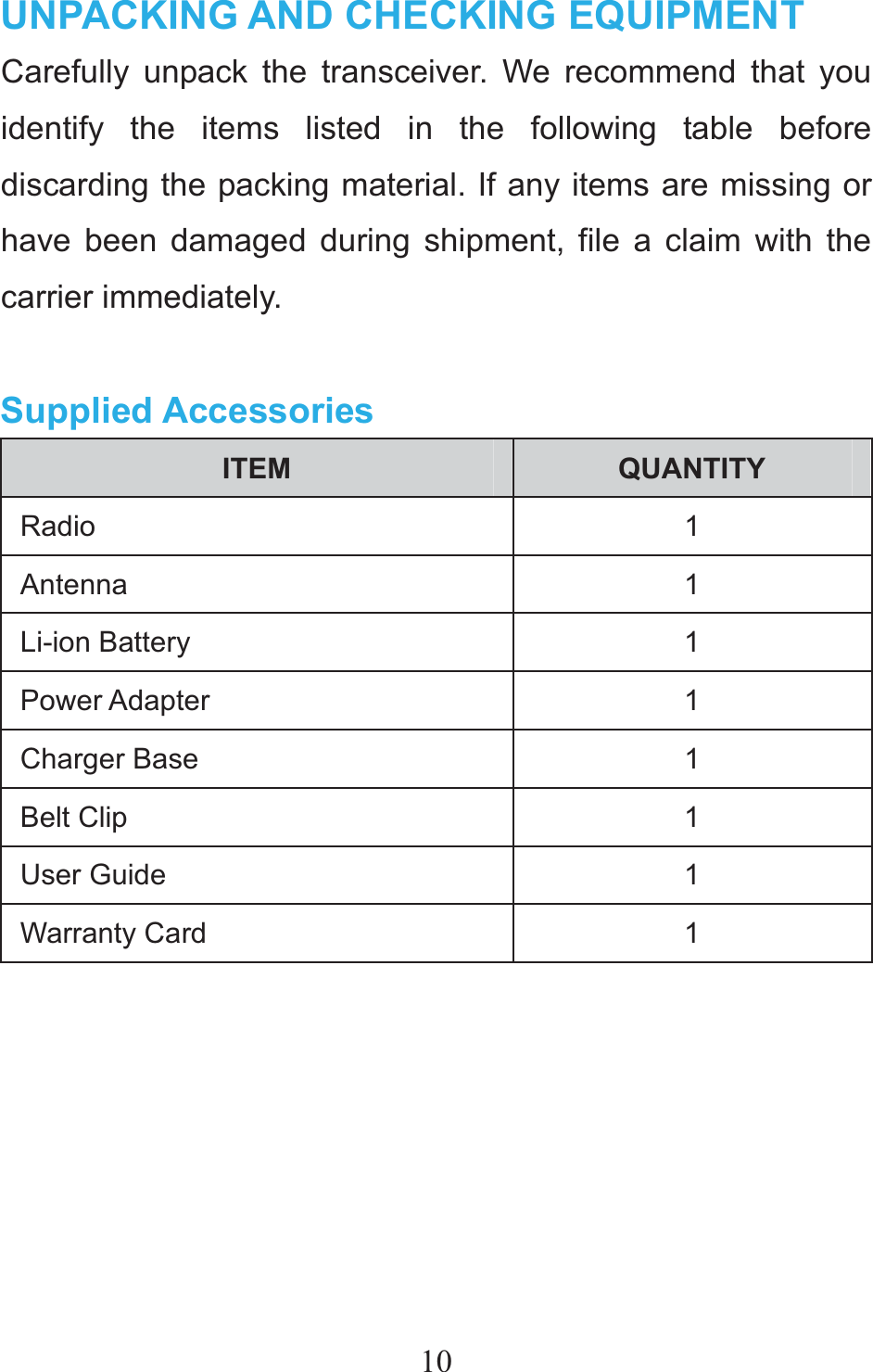
![16you press anyone of [P1],[P2]] keys, the time of pressing is over your setting time, then it’s a long time key, otherwise, it’s a short key Squelch Off and Squelch Off Momentary feature only to be enabled for analog channels. Status Indication LED Indicator LED Indicator Radio Status The LED glows red. Transmitting The LED flashes red. Low Battery The LED glows green. Receiving The LED flashed green. Scanning The LED glows orange.After voice communication ends, you can hold the [PTT] switch to talk while the LED glows orange.](https://usermanual.wiki/Vertex-Standard-LMR/VZ-30-G6-4/User-Guide-2482134-Page-20.png)
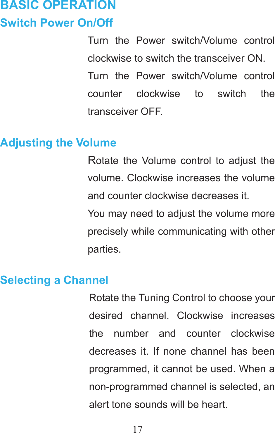
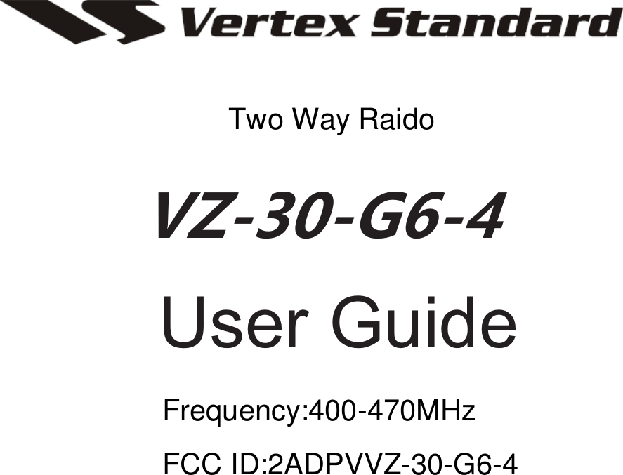
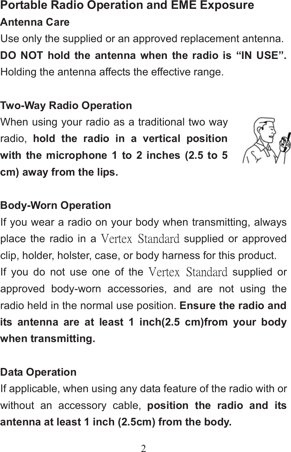
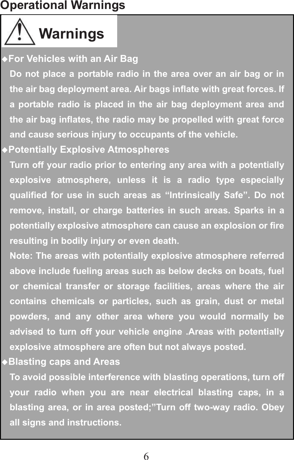
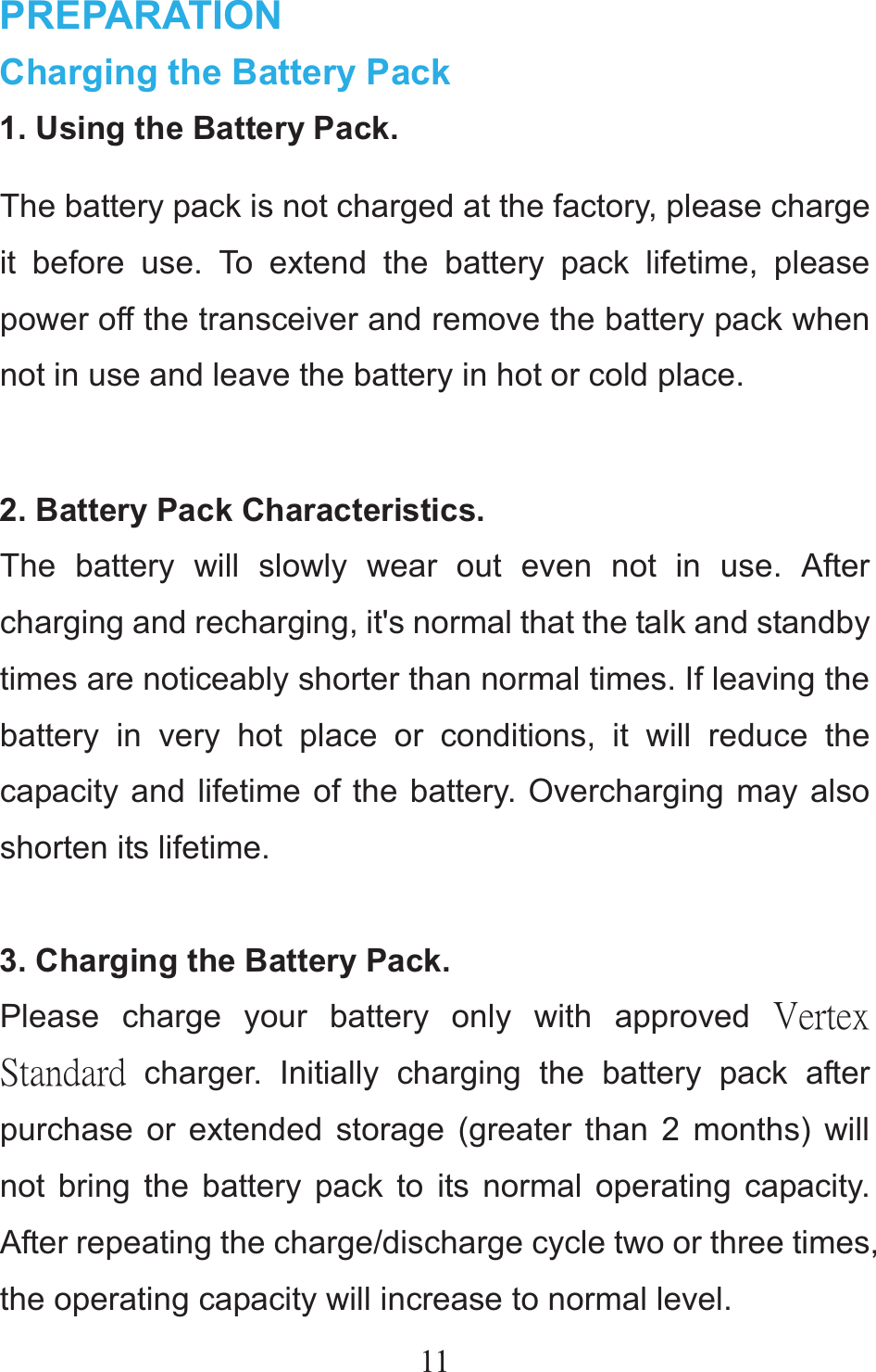
![18Transmitting You can transmit on an analog channel or digital channelˈbut should be in the same format when communicate, an analog channel can’t communicate with a digital channel. 1.On analog channel, press the [PTT]switch and speak into the microphone in your normal speaking voice. On digital channel, hold the [PTT] key to transmit a call to the private call contact preset for the current channel. ƹFor best sound quality at the receiving station, hold the microphone approximately 1.5 inches (3~6 cm) from your mouth. 2.Release the [PTT] switch to receive. Receiving On analog channels, your dealer may have programmed CTCSS/DCS, Scrambler signaling in your transceiver. If your selected channel is programmed with one of these features, you will hear calls only when another party in your system transmits.](https://usermanual.wiki/Vertex-Standard-LMR/VZ-30-G6-4/User-Guide-2482134-Page-22.png)
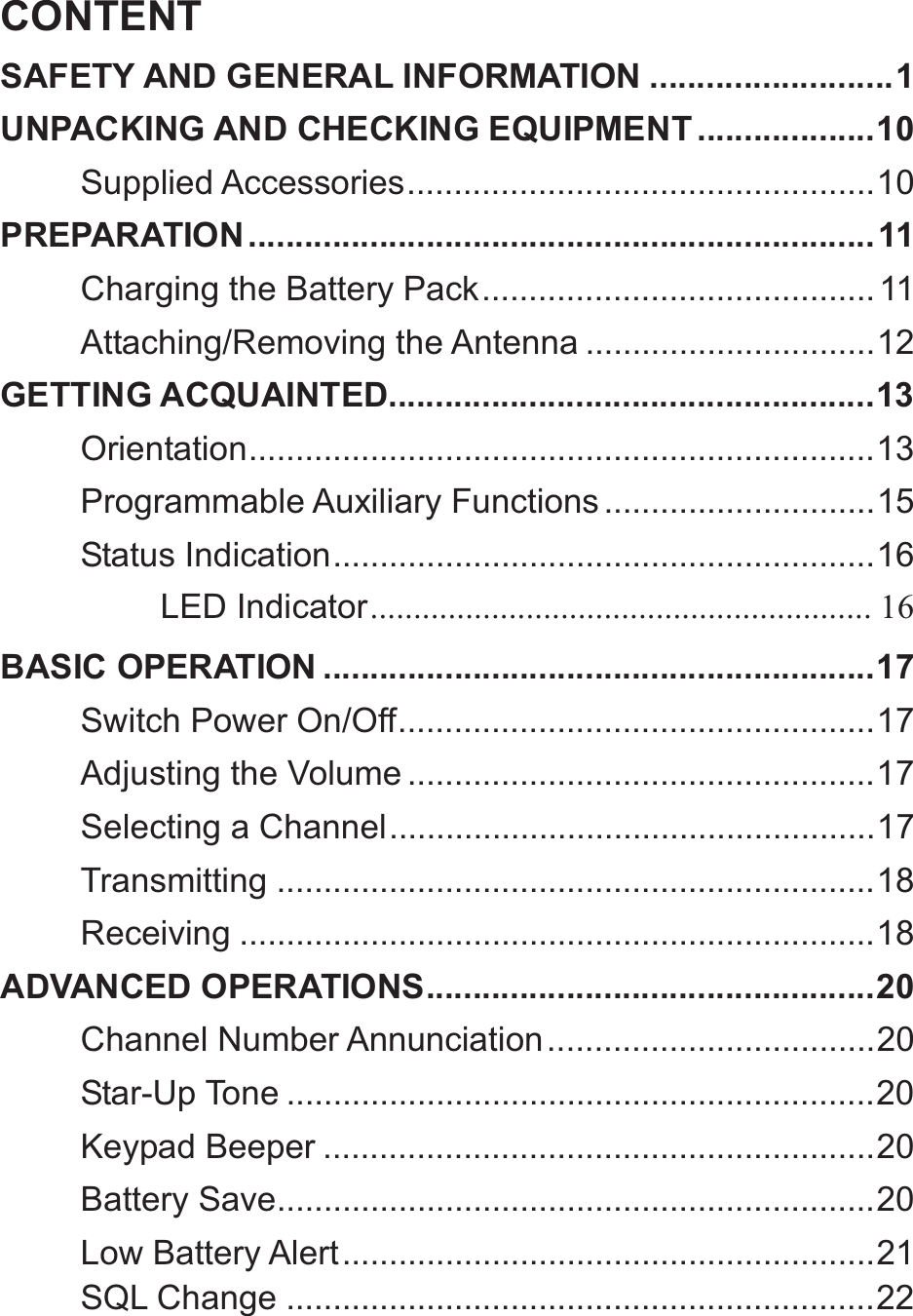
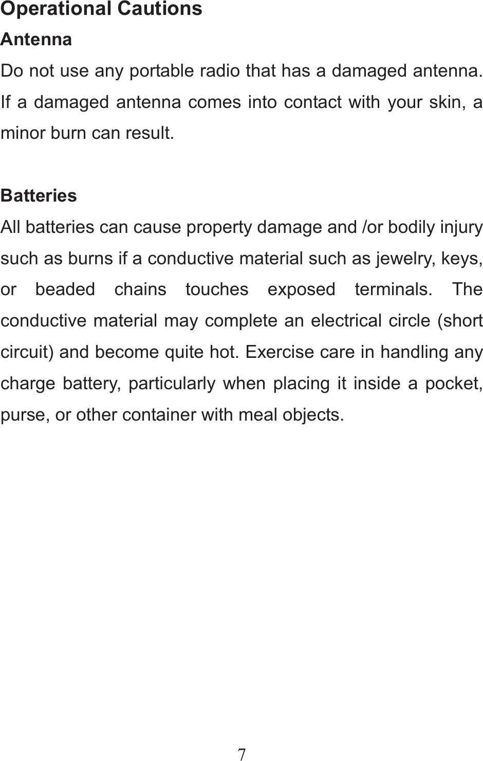
![20ADVANCED OPERATIONS (The following features should be programmed by your dealers). Channel Number Annunciation There are 3 kinds of the channel number annunciation: “Chinese Male Voice, English Male Voice(Default Setting), None”. When you turn the [Tuning Control], the transceiver sounds the current corresponding channel number. Star-Up Tone When you switch the transceiver ON, There will be a start-up tone. The default setting is ON. Keypad Beeper The transceiver beeps each time if you press a key on the keypad. The default setting is ON. Battery Save The battery save function decreases the amount of power used when signal is not being received and no operations are being performed (no keys are being](https://usermanual.wiki/Vertex-Standard-LMR/VZ-30-G6-4/User-Guide-2482134-Page-24.png)
![24you can use this feature to eliminate. The default setting is OFF. This feature is only for analog channel. Talk Around This feature is only enabled when there are different frequency between TX and RX. Press the programmed function key to activate the Talk Around feature. When activated, the RX frequency is used in place of the TX frequency when transmitting. The default setting is OFF. Scramble When scramble feature is activated, any other party listening on your channel is prevented from eavesdropping your conversation. The default setting is OFF. Calling Back This feature is only enabled for digital channels. When communication ends, but within the preset time period(The LED glows orange). Press and hold [PTT] switch to call back and continue to communicate. If over the preset time period(The LED light is off), press](https://usermanual.wiki/Vertex-Standard-LMR/VZ-30-G6-4/User-Guide-2482134-Page-28.png)
![25and hold [PTT] switch to call contact preset for the current digital channels. Only Receiving When this feature to be active, the transmission is prohibited, but can still receive the signals. The default setting is OFF. VOXPress the programmed VOX key to transmit hands-free with the transceiver or thru a headset. Re-press the programmed key to exit this feature. The default setting is OFF. ScanPress the programmed Scan key to initiate transceiver scanning from the current channel, and ascends through the channel numbers in scan list. The green LED solidly glows when a signal is re-received with signaling match on a channel. Press the Scan key again to exit transceiver scanning. There must be two memory channels at least.](https://usermanual.wiki/Vertex-Standard-LMR/VZ-30-G6-4/User-Guide-2482134-Page-29.png)