Vertex Standard USA 11464620 Handheld Portable UHF Non-Display fixed antenna User Manual EVX S24 OM ENG EC146U100 FCC 160817 indd
Vertex Standard USA, Inc. Handheld Portable UHF Non-Display fixed antenna EVX S24 OM ENG EC146U100 FCC 160817 indd
Contents
- 1. Users Manual
- 2. User Manual
User Manual
![EVX-S24 OPERATING MANUAL 7MIC/SP Jack(External MIC/SP)CONTROLS & CONNECTORSLED Indicator (Programmable) Default settings are: Steady Blue: Transmitting in Progress (Digital) Steady Red: Transmitting in Progress (Analog) Blinking Green: Busy Channel Steady Green: Channel Monitor Blinking Yellow: Emergency function is active Blinking Red: Low Battery PowerPTT SwitchSIDE Key (Programmable) Default settings are:Press Key: LAMP “On”Press and Hold Key: Non AssignmentMicro USB JackSpeakerMicrophoneAntenna JackVOL (Volume)/PWR (Power) KnobLCD (Liquid Crystal Display)[]/[] Key (Programmable) Default settings are: Press Key: Channel Up/Down Press & Hold Key: Speed Channel Up/Down[MODE( )] Key (Programmable) Default settings are: Press Key: User Set Mode Active Press & Hold Key: Key Lock FunctionBattery Cover Latch(Rear Side)Exhibit 8: Operating ManualFCC ID: AXI11464620IC: 10239A-11464620Vertex Standard LMR, Inc.](https://usermanual.wiki/Vertex-Standard-USA/11464620.User-Manual/User-Guide-3103379-Page-9.png)
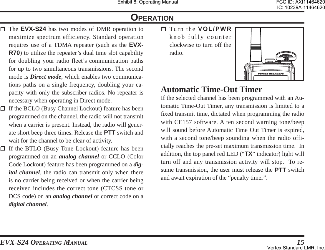
![EVX-S24 OPERATING MANUAL 13OPERATIONPreliminary Steps Install a battery pack into the transceiver and charge the battery fully, as described previously. Screw the supplied antenna onto the Antenna jack, as described previously. It is not recommended to operate this transceiver with-out an antenna connected. If you have a Speaker/Microphone, we recommend that it not be connected until you are familiar with the basic operation of the EVX-S24. Refer to next page for more information about Speaker/Microphone us-age.IMPORTANT NOTEThe dust- and waterproof rating of the transceiver (IP67) is assured only when the following condi-tions are met: Battery Cover is attached to the transceiver; Antenna is connected to the antenna jack;Rubber Cover is installed over the Micro USB jack.MIC/SP cap is installed in the MIC/SP jack. Or the Speaker/Microphone that approved with an IP67 rating by Vertex Standard is installed in the MIC/SP jack. Operation Quick Start Turn the top panel’s VOL/PWR knob clock-wise to turn on the radio. Press the []/[] key to choose the desired operating channel. If you want to select the operating channel from a different Channel Group, press (or press and hold) the Programmable key (assigned to the “Group Up/Down” function) to change desired Channel Group before selecting the operating channel. Rotate the VOL/PWR knob to set the volume level.Exhibit 8: Operating ManualFCC ID: AXI11464620IC: 10239A-11464620Vertex Standard LMR, Inc.](https://usermanual.wiki/Vertex-Standard-USA/11464620.User-Manual/User-Guide-3103379-Page-15.png)
![14 EVX-S24 OPERATING MANUALOPERATION To transmit, press and hold in the PTT switch. Speak into the micro-phone area of the front panel grille in a normal voice level. To return to the receive mode, release the PTT switch. Press the [MODE()] key to enter the User Set (Menu) Mode for acti-vating the various func-tions: press the []/[] key to select the desired function, and then press the [MODE( )] key to initiate it. See page 31 for more information regarding the “User Set (Menu)” mode. To install a speaker mi-crophone or other audio accessory, lift the rubber cap from the MIC/SP jack of the transceiver. Make sure that the transceiver is turned off, then insert the threaded microphone plug into the MIC/SP jack, and screw it into place until tight, being careful not to damage the Speaker/Microphone cable. Inserting the plug into the jack will disable the internal speaker. Hold the speaker grille up next to your ear while receiving. To transmit, press the PTT switch on the Speaker/Microphone, just as you would on the main transceiver’s body, and speak into the microphone on a normal voice level. Note 1) When you press the PTT switch on the Speaker/Microphone, it disables the internal micro-phone, and vice versa. 2) To keep the Dust- and Waterproof (IP67), the rub-ber cap should be reinstalled to the MIC/SP jack when not using the Speaker/Microphone. Exhibit 8: Operating ManualFCC ID: AXI11464620IC: 10239A-11464620Vertex Standard LMR, Inc.](https://usermanual.wiki/Vertex-Standard-USA/11464620.User-Manual/User-Guide-3103379-Page-16.png)
![16 EVX-S24 OPERATING MANUALARTS™ (Auto Range Transpond System)This system is designed to inform the operator when you and another ARTS™-equipped transceivers and stations are within communication range using the DCS Encoder/Decoder.During ARTS™ operation, when the radio receives an incoming ARTS™ signal, a short single beep will sound and “IN SERV” (“In Service”) will be indicated on the display for 2 seconds. If you move out of range for more than two minutes, your radio senses that no signal has been received, causing a short triple beep to sound and “OUT SERV” (“Out of Service”) will be indicated on the display for 2 seconds. Moving back into communications range as the ARTS™ signal transmission from another transceiver or station is back in range, a short single beep will again sound and “IN SERV” (“In Service”) will be indicated on the display for 2 seconds.OPERATIONLOCKIn order to prevent accidental channel changes or inadver-tent transmissions, various aspects of the Programmable keys and PTT switch may be locked.To activate the locking feature, press and hold the [MODE()] key.To cancel the key locking, press and hold the [MODE()] key again.You may change the lockout confi guration by the “User Set (Menu)” mode. See page 36 for more information.Exhibit 8: Operating ManualFCC ID: AXI11464620IC: 10239A-11464620Vertex Standard LMR, Inc.](https://usermanual.wiki/Vertex-Standard-USA/11464620.User-Manual/User-Guide-3103379-Page-18.png)
![EVX-S24 OPERATING MANUAL 17ADVANCED OPERATIONProgrammable Key FunctionsThe EVX-S24 provides four Programmable Function (PF) keys: [], [MODE( )], [] and [SIDE] keys.These PF keys can be customized, via programming by your Vertex Standard dealer, to meet your communica-tions/network requirements.The possible PF key programming features are illustrated on the next page, and their functions are explained from page 18. All functions can be assigned to any PF Key. Up to two functions can be assigned per key, with the feature being activated by: Short Press (SP) - Press and release Long Press (LP) - Press and holdIf further details are required, contact your Vertex Stan-dard dealer. In this chapter, the following icons are used to indicate features supported in either the “Analog” mode or “Digital” mode:: Indicates an “Analog” mode only feature.: Indicates a “Digital” mode only feature.For features that are available in both “Analog” and “Dig-ital” modes, no icon is shown.For future reference, the table on the right side of the page can be used to track each function assigned to the Pro-grammable Function Keys on your radio.Exhibit 8: Operating ManualFCC ID: AXI11464620IC: 10239A-11464620Vertex Standard LMR, Inc.](https://usermanual.wiki/Vertex-Standard-USA/11464620.User-Manual/User-Guide-3103379-Page-19.png)
![18 EVX-S24 OPERATING MANUALFUNCTIONPROGRAMMABLE KEY(PRESS KEY / PRESS AND HOLD KEY)[SIDE][][MODE][]None / / / /Monitor / / / /Lamp / / / /Low Power / / / /Privacy/Encryption / / / /Privacy Set / / / /SET ////SQL OFF / / / /SQL Set / / / /Beep OFF / / / /AF Min Volume / / / /Whisper / / / /Emergency1/ --- / --- / --- / ---Lone Worker / / / /Group Up / / / /Group Down / / / /CH Up / / / /CH Down / / / /Speed CH Up2--- / --- / --- / --- /Speed CH Down2--- / --- / --- / --- /PRI-1 / / / /PRI-2 / / / /PRI-2 Set / / / /PRI-2 Disable / / / /FUNCTIONPROGRAMMABLE KEY(PRESS KEY / PRESS AND HOLD KEY)[SIDE][][MODE][]Scan / / / /Group Scan / / / /Dual Watch / / / /Follow Me Scan / / / /Scan Set / / / /Group Scan Set / / / /TA Scan / / / /Talk Around / / / /Search / / / /Reset / / / /Code Up / / / /Code Down / / / /Speed Dial / / / /Call / / / /Status Up / / / /Status Down / / / /Status Check / / / /Duty / / / /ID Check / / / /Text Message / / / /TX Interrupt Remote Dekey(REMOTE HALT TX)////TX Save Disable / / / /Lock / / / /ADVANCED OPERATION1: Emergency function can not assign to the LP function.2: Speed CH Up/Down functions can not assign to the SP function.Exhibit 8: Operating ManualFCC ID: AXI11464620IC: 10239A-11464620Vertex Standard LMR, Inc.](https://usermanual.wiki/Vertex-Standard-USA/11464620.User-Manual/User-Guide-3103379-Page-20.png)
![EVX-S24 OPERATING MANUAL 19ADVANCED OPERATIONDescription of Operating Functions ENCRYPTION Analog Voice Inversion Encryption can be activated/deac-tivated by an assigned PF key.The “ ” icon will be indicated on the display when the Encryption feature is activated.PRIVACY SET You can change the privacy settings to best meet your se-curity requirements using this function: Activates the “Privacy Set” function by an assigned PF key. A tone will sound, and the “Tag” name corre-sponding with the current Privacy Code will appear on the display. Press the []/[] keys to select the desired Privacy Code. Up to 16 Privacy Codes are available for selec-tion. Press the [MODE( )] key to store the new setting. The display indicates “- SET -” briefl y, then reverts to the normal channel indication. You may cancel the new setting by press and holding the [MODE()] key. In this case, the display indi-cates “- CANCEL -” briefl y.MONITOR Any signaling features can be activated/deactivated by an assigned PF key. The LED indicator will glow green when the signaling feature is deactivated.LAMPIlluminates the back light of the display and keypad for fi ve seconds.LOW POWERToggle the radio’s transmit power “High” and “Low”. The battery life will be extended in the “Low Power” mode.The “L” icon will be indicated on the display when the radio’s transmitter is set to “Low Power” mode.PRIVACY Digital Privacy feature can be activated/deactivated by an assigned PF key. The Privacy feature initiates an encryp-tion algorithm that will protect your communication from unauthorized eavesdropping.The “ ” icon will be indicated on the display when the Privacy feature is activated.Exhibit 8: Operating ManualFCC ID: AXI11464620IC: 10239A-11464620Vertex Standard LMR, Inc.](https://usermanual.wiki/Vertex-Standard-USA/11464620.User-Manual/User-Guide-3103379-Page-21.png)
![20 EVX-S24 OPERATING MANUALADVANCED OPERATIONSETActivates the “User Set (Menu)” mode. See page 31 for more information of the “User Set (Menu)” mode.SQL OFF SQL OFF opens the radio squelch/unmute the audio to hear background noise.SQL SET You can manually adjust the squelch level using this func-tion: Activates the “SQL Set” function by an assigned PF key. A tone will sound, and the current squelch level will appear on the display. Press the []/[] keys to select the desired squelch level. Available selections are “SQLLV OP (Open)”, “SQLLV TH (Threshold)”, “SQLLV NM (Normal)” and “SQLLV TI (Tight)”. Press the [MODE( )] key to store the new setting. The display indicates “- SET -” briefl y, then reverts to the normal channel indication. You may cancel the new setting by press and holding the [MODE()] key. In this case, the display indi-cates “- CANCEL -” briefl y.BEEP OFFActivation of Beep off disables all radio beeps (alert tones) temporarily. Radio beeps will be restored by pressing the PF key again.When the Beep Off function is “on” and “off”, the display indicates briefl y “BEEP OFF” and “BEEP ON”.AF MIN VOLUMEPress the assigned PF key, the display indicates “AFATT ON” briefl y, and reduce the audio output to the (lower) level programmed. Again press the assigned PF key, the display indicates “AFATT OF” briefl y, and resume nor-mal audio output level.You may change the programmed (lower) level by the “User Set (Menu)” mode. See page 34 for more informa-tion.WHISPERWhisper allows the user to increase the microphone gain, allowing the operator to speak in a low voice (whisper) temporarily when transmitting. The radio can go back to normal microphone gain by pressing the assigned PF key a second time.When the Whisper function is “on” and “off”, the display indicates briefl y “WHISP ON” and “WHISP OF”.Exhibit 8: Operating ManualFCC ID: AXI11464620IC: 10239A-11464620Vertex Standard LMR, Inc.](https://usermanual.wiki/Vertex-Standard-USA/11464620.User-Manual/User-Guide-3103379-Page-22.png)
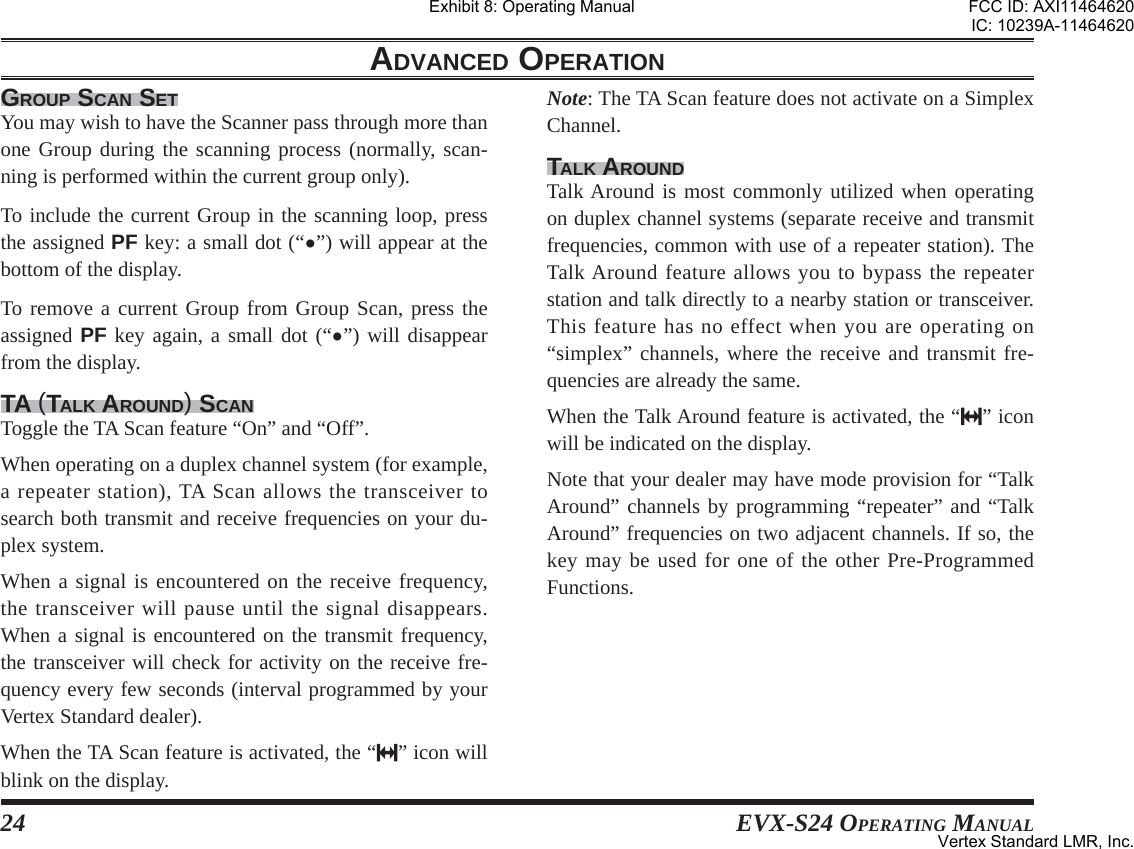
![EVX-S24 OPERATING MANUAL 23DUAL WATCHThe Dual Watch feature is similar to the SCAN feature, except that only two channels are monitored: The current operating channel The Priority channel (PRI-1 or PRI-2).To activate Dual Watch: Press the assigned PF key to activate the Dual Watch feature. The scanner will search the two channels and pause when it fi nds a transmission on either channel.To stop Dual Watch: Press the assigned PF key to disable the Dual Watch feature. The radio receives the current operating chan-nel.When the Dual Watch feature is activated, the “D” icon will be indicated on the display.FOLLOW ME SCANThe Follow Me Scan feature checks an user-assigned pri-ority channel in addition to the channels previously pre-programmed into a radio’s scan list. For example, if only Channels 1, 3, and 5 (of the 8 available channels) are designated for “Scanning”, the user may assign Channel 2 as the “user-assigned” priority channel via the Follow Me Scan.To activate Follow Me Scan, fi rst select the channel you want to designate as the “user-assigned priority channel” by pressing the []/[] keys on the desired channel. Next, press, (or press and hold), the assigned PF key. The display will indicate “FM SCAN”.SCAN SETScan Set enables the user to add or delete a current chan-nel to a pre-programmed scan list.When store a particular channel to your scanning list, the display indicates “SCN SET” briefl y. When delete a chan-nel from your scanning list, the display indicates “SCN SKIP” briefl y.When the scanner is paused, you may remove the channel from the scan list temporarily by pressing the assigned PF key.ADVANCED OPERATIONExhibit 8: Operating ManualFCC ID: AXI11464620IC: 10239A-11464620Vertex Standard LMR, Inc.](https://usermanual.wiki/Vertex-Standard-USA/11464620.User-Manual/User-Guide-3103379-Page-25.png)
![EVX-S24 OPERATING MANUAL 25SEARCH Identify the signal of the closest site (station) with the strongest signal strength (RSSI) and then connect to that site (station) automatically.Site Search enables the radio to move between multiple sites seamlessly by identifying the strongest, closest site signal. The radio will dynamically change it’s pre-pro-grammed home site to the site with the strongest signal in range when Site Search is activated.Note: This feature may be possibility assigned to the channel by your administrator or Vertex Standard dealer.RESET When operating in the selective call feature, press the assigned PF key to terminate the communication by the selective call function.CODE UP/DOWN Select a 2-Tone, 5-Tone, or DTMF encode code from the pre-programmed encode list. Press the PTT switch to send a selected code.SPEED DIALYour Vertex Standard dealer may have pre-programmed Auto-Dial telephone number memories into your radio.To dial a number: Press the assigned PF key. The “Tag” name corre-sponding with the current Auto-Dial memory will ap-pear on the display. Press the []/[] keys to select the Auto-Dial memo-ry you wish to dial. Press the PTT switch to send a pre-defined DTMF tone. The DTMF tones sent during the dialing se-quence will be heard in the speaker.CALLThe Call feature is different for each type of the signaling system:WHEN USING THE 2-TONE/5-TONE SIGNALING SYSTEMSend a pre-programmed 2-Tone/5-Tone Call Signal with an one touch PF key.WHEN USING THE MDC1200 SYSTEMConfi rm the Contact Alias of the MDC1200® Signaling feature, and you may perform the following operation to that Contact Alias. Available operations are Call Alert, Sel Call, Radio Check, Stun, and Revive.Call AlertYou may transmit the Call Alert to the selected Contact Alias. Press the assigned PF key to activate the MDC1200 Call feature. Press the []/[] keys to recall the Contact Alias you ADVANCED OPERATIONExhibit 8: Operating ManualFCC ID: AXI11464620IC: 10239A-11464620Vertex Standard LMR, Inc.](https://usermanual.wiki/Vertex-Standard-USA/11464620.User-Manual/User-Guide-3103379-Page-27.png)
![26 EVX-S24 OPERATING MANUALwish to contact, then press the [MODE( )] key.Press the []/[] keys to select “CALL ALT”. Press the [MODE( )] key to transmit the Call Alert command to the designated radio. If the designated radio is active, the designated radio transmits the ACK command and displays your ID number on the display. Sel CallYou may call the selected Contact Alias. Press the assigned PF key to activate the MDC1200 Call feature. Press the []/[] keys to recall the Contact Alias you wish to contact, then press the [MODE()] key.Press the []/[] keys to select “SEL CALL”. Press the [MODE( )] key to transmit the Selective Call command to the designated radio. If the desig-nated radio is active, the designated radio transmits the ACK command and displays your ID number on the display.Radio CheckYou may check the radio status of the selected Contact Alias. Press the assigned PF key to activate the MDC1200 Call feature. Press the []/[] keys to recall the Contact Alias you wish to contact, then press the [MODE()] key.Press the []/[] keys to select “RADIO CK”. Press the [MODE()] key to transmit the Radio Sta-tus command to the designated radio (the display will indicate “-CAL IN-”). If the designated radio is “alive”, or in range and powered on, the designated radio trans-mits the ACK command, and then your radio’s display indicates “ACK RECV”. If not, your radio’s display indicates “-NO ACK-”.ReviveYou may revive the stunned radio by following the listed steps. Press the assigned PF key to activate the MDC1200 Call feature. Press the []/[] keys to recall the Contact Alias you wish to revive, then press the [MODE()] key.Press the []/[] keys to select “REVIVE”. Press the [MODE()] key to transmit the revive command to the stunned radio (the display will indi-cate “-CAL IN-”). When the stunned radio receives the revive command, the stunned radio revives, and then transmits the ACK command automatically. Your radio’s display indicates “ACK RECV”. If your ra-dio’s display indicates “-NO ACK-”, the revive com-mand did not succeed.ADVANCED OPERATIONExhibit 8: Operating ManualFCC ID: AXI11464620IC: 10239A-11464620Vertex Standard LMR, Inc.](https://usermanual.wiki/Vertex-Standard-USA/11464620.User-Manual/User-Guide-3103379-Page-28.png)
![EVX-S24 OPERATING MANUAL 27StunYou may stun a selected radio in your fl eet (temporarily disable from transmitting/receiving) forcibly by remote control. Press the assigned PF key to activate the MDC1200 Call feature. Press the []/[] keys to recall the Contact Alias you wish to stun, then press the [MODE()] key.Press the []/[] keys to select “STUN”. Press the [MODE( )] key to transmit the stun com-mand to the designated radio (the display will indicate “-CAL IN-”). If the designated radio is alive, the des-ignated radio transmits the ACK command and stuns it. If not, your radio’s display indicates “-NO ACK-”, the disabling command did not succeed.The Stunned radio will revive by the “Revive” function described previously.WHEN OPERATING IN THE DIGITAL MODE Press the assigned PF key to activate the Call feature. Press the []/[] keys to select the Contact Alias. If the TX ID Type of the selected Contact Alias is “Group Call” or “All Call” (indicates the “ ” or “” icon on the display), press the [MODE()] key twice to display the ID code of the selected Contact Alias. If the TX ID type of the selected Contact Alias is “Individual Call” (indicates “ ” icon on the dis-play), you may perform the “Call Alert”, View ID, “Radio Check”, “Radio Enable”, or “Radio Dis-able” operation.Call AlertYou may call the selected Contact Alias. Press the assigned PF key to activate the Call feature. Press the []/[] keys to recall the Contact Alias you wish to contact, then press the [MODE()] key.Press the []/[] keys to select “CALL ALT”. Press the [MODE( )] key to transmit the Call Alert command to the designated radio. If the designated radio is active, the designated radio transmits the ACK command and displays your ID number on the display. If not, your radio’s display indicates “-NO ACK-”.View IDYou may confirm the ID code of the selected Contact Alias. Press the assigned PF key to activate the Call feature. Press the []/[] keys to recall the Contact Alias you wish to confirm the ID code, then press the [MODE()] key.Press the []/[] keys to select “VIEW ID”. Press the [MODE()] key to display the ID code of the selected Contact Alias.ADVANCED OPERATIONExhibit 8: Operating ManualFCC ID: AXI11464620IC: 10239A-11464620Vertex Standard LMR, Inc.](https://usermanual.wiki/Vertex-Standard-USA/11464620.User-Manual/User-Guide-3103379-Page-29.png)
![28 EVX-S24 OPERATING MANUALRadio CheckYou may check the radio status of the selected Contact Alias. Press the assigned PF key to activate the Call feature. Press the []/[] keys to recall the Contact Alias you wish to check, then press the [MODE()] key.Press the []/[] keys to select “RADIO CK”. Press the [MODE( )] key to transmit the Radio Sta-tus command to the designated radio. If the designated radio is alive, the designated radio transmits the ACK command, and then your radio’s display indicates “ACK RECV”. If not, your radio’s display indicates “-NO ACK-”.ReviveYou may revive the stunned radio by following the listed steps. Press the assigned PF key to activate the Call feature. Press the []/[] keys to recall the Contact Alias you wish to revive, then press the [MODE()] key.Press the []/[] keys to select “REVIVE”. Press the [MODE()] key to transmit the revive command to the disabled radio. When the stunned ra-dio receives the revive command, the stunned radio re-vives, and then transmits the ACK command automati-cally. Your radio’s display indicates “ACK RECV”. If your radio’s display indicates “-NO ACK-”, the revive command did not succeed.StunYou may stun a selected radio in your fl eet (temporarily disable from transmitting/receiving) forcibly by remote control. Press the assigned PF key to activate the Call feature. Press the []/[] keys to recall the Contact Alias you wish to stun, then press the [MODE()] key.Press the []/[] keys to select “STUN”. Press the [MODE( )] key to transmit the stun com-mand to the designated radio. If the designated radio is alive, the designated radio transmits the ACK com-mand and stuns it. If not, your radio’s display indicates “-NO ACK-”, the disabling command did not succeed.The stunned radio will revive by the “Revive” function described previously.STATUS UP/DOWN Select a 5-Tone status code from the pre-defined status list.STATUS CHECK Check the 5-Tone receive status code. When you press the assigned PF key, the display will indicate the “Message” corresponding to the receive status condition per the pre-defi ned status list.ADVANCED OPERATIONExhibit 8: Operating ManualFCC ID: AXI11464620IC: 10239A-11464620Vertex Standard LMR, Inc.](https://usermanual.wiki/Vertex-Standard-USA/11464620.User-Manual/User-Guide-3103379-Page-30.png)
![EVX-S24 OPERATING MANUAL 29DUTY The Duty function is specifi c to paging operation. When Duty mode is “ON” the user will hear all traffi c (specifi c to sub audio signaling) on the paging channel. The paging alert will sound when the programmed 2-Tone or 5-Tone sub audio signal is received.If Duty mode is “OFF”, normal radio traffi c is not heard on the paging channel. The radio will only unmute and sound the paging alert with the programmed 2-Tone or 5-Tone signal is received.ID CHECKThis function allows you to confi rm the logged ID of the operating system which set to the current operating chan-nel. Available operating system are 5-Tone ID, DTMF ID, MDC1200® ID, and Digital ID. Press the assigned PF key to display the logged ID. Press the []/[] keys to select the logged ID. Press and hold in the [SIDE] key to toggle the display between the “ID Code display” and “Channel Tag dis-play”. Press the [SIDE] key to revert to the normal channel indication.TEXT MESSAGEYou may receive/send the message from/to other radio. See page 35 for more information of the message feature.TX INTERRUPT REMOTE DEKEY (REMOTE HALT TX)This feature allows a priority user (assigned with the pro-gramming software) the ability to halt or “interrupt” any current transmission. The channel is then open for a prior-ity message to be sent. Transmit Interrupt functionality ensures connection of critical messages.Press the assigned PF key to halt any current transmis-sion. The channel will clear, then press the PTT button to transmit the priority message.ADVANCED OPERATIONExhibit 8: Operating ManualFCC ID: AXI11464620IC: 10239A-11464620Vertex Standard LMR, Inc.](https://usermanual.wiki/Vertex-Standard-USA/11464620.User-Manual/User-Guide-3103379-Page-31.png)
![EVX-S24 OPERATING MANUAL 31USER SET (MENU) MODE The “User Set” (Menu) Mode allows the user to defi ne or confi gure various settings, such as Squelch, Key lockout confi guration, etc. The basic operation method of the “User Set” (Menu) Mode is as follows: Press the [MODE()] key to enter the “User Set” (Menu) Mode. Select the Set Mode item you wish to change using the []/[] keys, then press the [MODE()] key. Adjust the setting of the selected item using the []/[] keys. You may revert to the previous step by pressing the [SIDE] key. Press the [MODE()] key to save the new setting and exits to normal operation. You may exit to normal operation without saving the new setting by press and holding the [MODE()] key.The possible setting features are listed at the right box, and their operations are explained from next page. In this chapter, the following icons are used to indicate item (or feature) supported in either the “Analog” mode or “Digital” mode:: Indicates an “Analog” mode only feature.: Indicates a “Digital” mode only feature.For item (or feature) that are available in both “Analog” and “Digital” modes, no icon is shown.LISTDigital Contact List5-Tone Code Select2-Tone Code SelectDTMF Code SelectMDC1200 ID SelectGroupScanUtilityMonitorSQL OFFPowerMinimum Volume LevelBeepBeep LevelSQL LevelLightingPrivacy/EncryptionPrivacy SelectLone WorkerBellPRI-2TAScan Set/SkipGroup Scan Set/SkipDutyTX Save DisableLock KeyLock PTTDIALMessageHistoryLOCKThere is function which is not called depend-ing on the state of the operating channel when entering the User Set (Menu) Mode.For example, if you are operating in a “Digital” channel, the SQL SET function has not been recalled.Exhibit 8: Operating ManualFCC ID: AXI11464620IC: 10239A-11464620Vertex Standard LMR, Inc.](https://usermanual.wiki/Vertex-Standard-USA/11464620.User-Manual/User-Guide-3103379-Page-33.png)
![32 EVX-S24 OPERATING MANUALLISTIn this item, you may operate the following functions: Digital Contact List 5-Tone Code Select 2-Tone Code Select DTMF Code Select MDC1200 ID SelectPress the []/[] keys to recall the function you wish to operate, then press the [MODE()] key to activate them. Refer to follows for detailed operation of each function.DIGITAL CONTACT LIST Digital Contact List allows you to confirm the Contact Alias on the Digital mode by pressing the []/[] keys.If the TX ID Type of the selected Contact Alias is “Group Call” or “All Call” (indicates the “ ” or “ ” icon on the display), you may confi rm the ID code of the selected Con-tact Alias.If the TX ID type of the selected Contact Alias is “Indi-vidual Call” (indicates “ ” icon on the display), you may perform the “Call Alert”, View ID, “Radio Check”, “Radio Enable”, or “Radio Disable” operation. See page 27 for detail of the Digital Call operation.USER SET (MENU) MODE 5-TONE CODE SELECT 5-Tone Code Select allows you to select/send the 5-Tone encode code of the pre-programmed encoder list.Press the []/[] keys to select the 5-Tone encode code, and then press the [MODE()] key to transmit the se-lected 5-Tone encode code. 2-TONE CODE SELECT 2-Tone Code Select allows you to select/send the 2-Tone encode code of the pre-programmed encoder list.Press the []/[] keys to select the 2-Tone encode code, and then press the [MODE()] key to transmit the se-lected 2-Tone encode code. DTMF CODE SELECT DTMF Code Select allows you to select/send the DTMF Page code of the pre-programmed encoder list.Press the []/[] keys to select the DTMF Page code, and then press the [MODE()] key to transmit the se-lected DTMF Page code. MDC1200 ID SELECT MDC1200 ID Select allows you to select the Contact Alias on the MDC1200® Signaling feature by pressing the []/[] keys, and you may perform “Call Alert”, “Sel Call”, “Radio Check”, “Stun”, and “Revive” operation. See page 25 for detail of the MDC1200 Call operation.Exhibit 8: Operating ManualFCC ID: AXI11464620IC: 10239A-11464620Vertex Standard LMR, Inc.](https://usermanual.wiki/Vertex-Standard-USA/11464620.User-Manual/User-Guide-3103379-Page-34.png)
![EVX-S24 OPERATING MANUAL 33GROUPYou may select a different group of channels. Press the []/[] keys to recall the desired group. A group number will appear at the upper right corner and a group name will appear briefl y on the display. Press the [MODE()] key to accept the group.SCANIn this item, you may activate/deactivate the Scan func-tion. Available selections are:OFF: Stop the scan operation of the currently run-ning.Scan: Stop the scan operation of the currently run-ning (if activated), and then start the Scan operation. See page 22 for detail of the Scan operation.Group Scan: Stop the scan operation of the currently run-ning (if activated), and then start the Group Scan operation. See page 22 for detail of the Group Scan operation.FM Scan: Stop the scan operation of the currently run-ning (if activated), and then start the FM (Follow Me) Scan operation. See page 22 for detail of the Follow Me Scan operation.Dual Watch: Stop the scan operation of the currently run-ning (if activated), and then start the Dual Watch operation. See page 23 for detail of the Dual Watch operation.TA Scan: Stop the scan operation of the currently running (if activated), and then start the TA (Talk Around) Scan operation. See page 24 for detail of the TA Scan operation.USER SET (MENU) MODE Exhibit 8: Operating ManualFCC ID: AXI11464620IC: 10239A-11464620Vertex Standard LMR, Inc.](https://usermanual.wiki/Vertex-Standard-USA/11464620.User-Manual/User-Guide-3103379-Page-35.png)
![34 EVX-S24 OPERATING MANUALUTILITYIn this item, you may operate the following functions: Monitor SQL OFF Power Minimum Volume Level Beep Beep Level SQL Level Lighting Privacy/Encryption Privacy Select Lone Worker Bell PRI-2 TA Scan Set/Skip Group Scan Set/Skip Duty TX Save Disable (Transmit Battery Saver Disable) Lock Key Lock PTTPress the []/[] keys to recall the function you wish to operate, then press the [MODE()] key to activate them. Refer to follows for detailed operation of each function.MONITOR You may toggle the any signaling feature “On” and “Off” by pressing the []/[] keys.SQL OFF You may toggle the squelch circuit “On” and “Off” by pressing the []/[] keys.POWERYou may toggle the radio’s transmit power “High” and “Low” by pressing the []/[] keys.MINIMUM VOLUME LEVELYou may set the audio volume level when activating the AF Min Volume function by pressing the []/[] keys. Available selections are “0” ~ “255”.BEEPYou may toggle the radio beeps “On” and “Off” by press-ing the []/[] keys.BEEP LEVELYou may set the radio beep level by pressing the []/[] keys. Available selections are “0” ~ “15”.SQL LEVEL You may select the squelch level by pressing the []/[] keys. Available selections are “SQLLV OP (Open)”, “SQLLV TH (Threshold)”, “SQLLV NM (Normal)” and “SQLLV TI (Tight)”.USER SET (MENU) MODE Exhibit 8: Operating ManualFCC ID: AXI11464620IC: 10239A-11464620Vertex Standard LMR, Inc.](https://usermanual.wiki/Vertex-Standard-USA/11464620.User-Manual/User-Guide-3103379-Page-36.png)
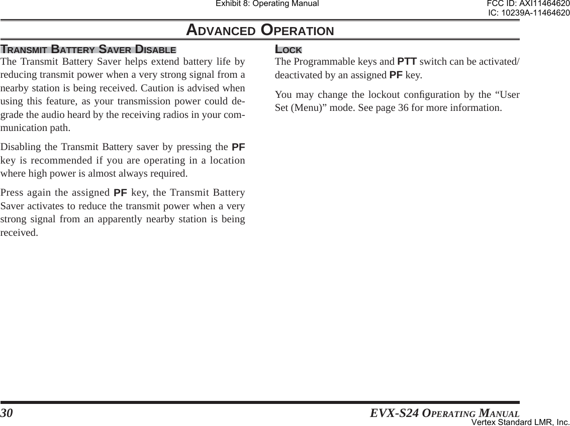
![EVX-S24 OPERATING MANUAL 35LIGHTINGYou may toggle the back light of the display and keypad “On” and “Off” by pressing the []/[] keys.PRIVACY / ENCRYPTION You may toggle the Digital Privacy feature or Analog Voice Inversion Encryption feature “On” and “Off” by pressing the []/[] keys.PRIVACY SELECT You may select the Privacy Code for the Privacy feature by pressing the []/[] keys. Available selections are “1” ~ “16”.LONE WORKERYou may toggle the Lone Worker feature “On” and “Off” by pressing the []/[] keys.BELL You may select the CTCSS/DCS Bell function “On” or “Off” by pressing the []/[] keys.When the CTCSS/DCS Bell function is set to “On”, the alert tone activates when receive the signal including a CTCSS or DCS tone which matches that set into your radio.USER SET (MENU) MODE PRI-2You may enable/disable to set the current operating chan-nel to the Priority Channel of the current group (Priority-2 Channel) by pressing the []/[] keys.TAYou may toggle the Talk Around feature “On” and “Off” by pressing the []/[] keys. See page 24 for detail of the Talk Around feature.SCAN SET/SKIPYou may add/delete the current channel to/from your scanning list by pressing the []/[] keys.GROUP SCAN SET/SKIPYou may add/delete the current group to/from your scan-ning process by pressing the []/[] keys.DUTY You may toggle the Duty function “On” and “Off” by pressing the []/[] keys. See page 29 for detail of the Duty function.TX SAVE DISABLE (TRANSMIT BATTERY SAVER DISABLE)You may activate/deactivate the Transmit Battery Saver Disable function by pressing the []/[] keys. See page 30 for detail of the Transmit Battery Saver Disable func-tion.Exhibit 8: Operating ManualFCC ID: AXI11464620IC: 10239A-11464620Vertex Standard LMR, Inc.](https://usermanual.wiki/Vertex-Standard-USA/11464620.User-Manual/User-Guide-3103379-Page-37.png)
![36 EVX-S24 OPERATING MANUALLOCK KEYYou may enable/disable the Programmable Function Keys by the Key Lock function. Available Values:LOCK: The Programmable Function Keys will be locked by the Key Lock function.FREE: The Programmable Function Keys will not be locked by the Key Lock function.LOCK PTTYou may enable/disable the PTT switch by the Key Lock function. Available Values:LOCK: The PTT switch will be locked by the Key Lock function.FREE: The PTT switch will not be locked by the Key Lock function.DIALIn this item, you may dial the DTMF Auto-Dial telephone number which was pre-programmed. Press the []/[] keys to select the DTMF Auto-Dial telephone number you wish to dial. Press the PTT switch to send a pre-defined DTMF tone, and the DTMF tones sent during the dialing se-quence will be heard in the speaker.MESSAGEThe Message feature is different by the operating system. Refer to follows for detailed operation of each operating system.DIGITAL MODE Message feature on the “Digital” mode, you may receive/send the text message from/to other radio. Press the []/[] keys to select either of the func-tions “INBOX” and “SEL MSG” which you want to. INBOX: Confi rm/delete the received text message. SEL MSG: Send the text message to other radio. Press the [MODE()] key to accept the selected function. Refer to follows for detailed operation of each function.“INBOX” functionIn this function, you may confi rm/delete the received text message. Press the []/[] keys to select “INBOX”, then press the [MODE()] key to accept it. Press the []/[] keys to select the received text message. The EVX-S24 can memorize up to 20 mes-sages (fi rst-in fi rst-out basis). You may fi nd the “ALL Delete” selection which is located at the last message loop. Describes details of this selection in the next paragraph.USER SET (MENU) MODE Exhibit 8: Operating ManualFCC ID: AXI11464620IC: 10239A-11464620Vertex Standard LMR, Inc.](https://usermanual.wiki/Vertex-Standard-USA/11464620.User-Manual/User-Guide-3103379-Page-38.png)
![EVX-S24 OPERATING MANUAL 37 Press and hold in the [SIDE] key to confi rm the “Call ID” of the selected message. If you want to delete the selected message: Press the [SIDE] key again to indicate the “Delete” selection. Press the []/[] keys to select the “Yes”, then press the [MODE()] key. You may cancel the deleting the message by select-ing the “No” instead “Yes” in the above step.ALL Delete: You may delete the all text messages at once. Press the []/[] keys to select the “ALL Delete” selection which is located at the last message loop. Press the []/[] keys to select the “Yes”, then press the [MODE( )] key. You may cancel the deleting the all text messages by selecting the “No” instead “Yes” in the above step.“SEL MSG” functionIn this function, you may send the text message to other radio. Press the []/[] keys to select “SEL MSG”, then press the [MODE()] key to accept it. Press the []/[] keys to select the message you wish to send. Press the [MODE( )] key to send the message.ANALOG MODE Message feature on the “Analog” mode, you may send the 5-Tone status text of the pre-programmed encoder list, and confi rm the “Message” corresponding to that received 5-Tone status text.Sending the Message Press the []/[] keys to select “SELECT”. Press the [MODE()] key, then press the []/[] keys to select the “Message” you wish to send. Press the [MODE( )] key to send the message.Confi rm the Message Press the []/[] keys to select “CHECK”. Press the [MODE()] key, then press the []/[] keys to select the received “Message”.USER SET (MENU) MODE Exhibit 8: Operating ManualFCC ID: AXI11464620IC: 10239A-11464620Vertex Standard LMR, Inc.](https://usermanual.wiki/Vertex-Standard-USA/11464620.User-Manual/User-Guide-3103379-Page-39.png)
![38 EVX-S24 OPERATING MANUALHISTORYIn this item, you may confi rm the history of the received station’s ID of the operating system which set to the cur-rent operating channel. Available operating system are Digital ID, 5-Tone ID, DTMF ID, and MDC1200® ID. Press the []/[] keys to scroll the received station’s ID of the operating system which set to the current op-erating channel. Press and hold in the [SIDE] key to indicate the “Channel Tag (Name)” which received that station’s ID, if desired.USER SET (MENU) MODE LOCKIn this item, you may lock the Programmable keys and PTT switch to prevent accidental channel change or inad-vertent transmission.To locked out the key locking, press and hold the [MODE()] key.You may change the lockout confi guration by the “Lock Key” and “Lock PTT” functions in the “Utility” item of this “User Set (Menu)” mode. See page 36 for more infor-mation.Exhibit 8: Operating ManualFCC ID: AXI11464620IC: 10239A-11464620Vertex Standard LMR, Inc.](https://usermanual.wiki/Vertex-Standard-USA/11464620.User-Manual/User-Guide-3103379-Page-40.png)