Vios Medical CS2050 Vios Monitoring System (VMS) User Manual
Vios Medical Inc Vios Monitoring System (VMS)
UserManual.wiki
>
Vios Medical
>
CS2050 User Manual
User manual
Navigation menu
Upload a User Manual
Namespaces
Wiki Guide
HTML
PDF
Info
Views
User Manual
Discussion / Help
Navigation
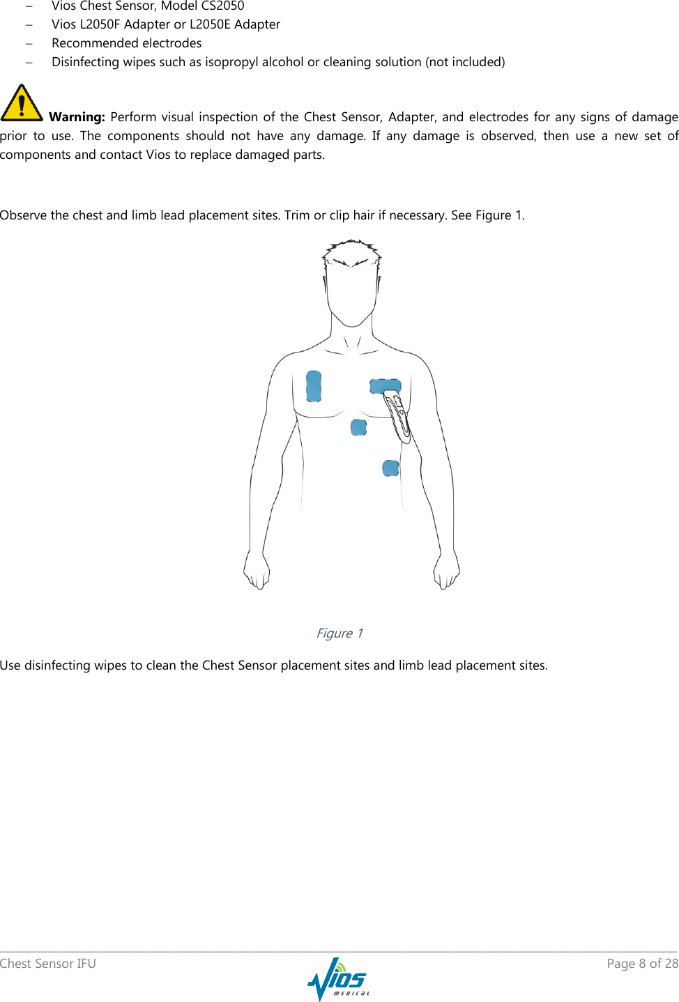

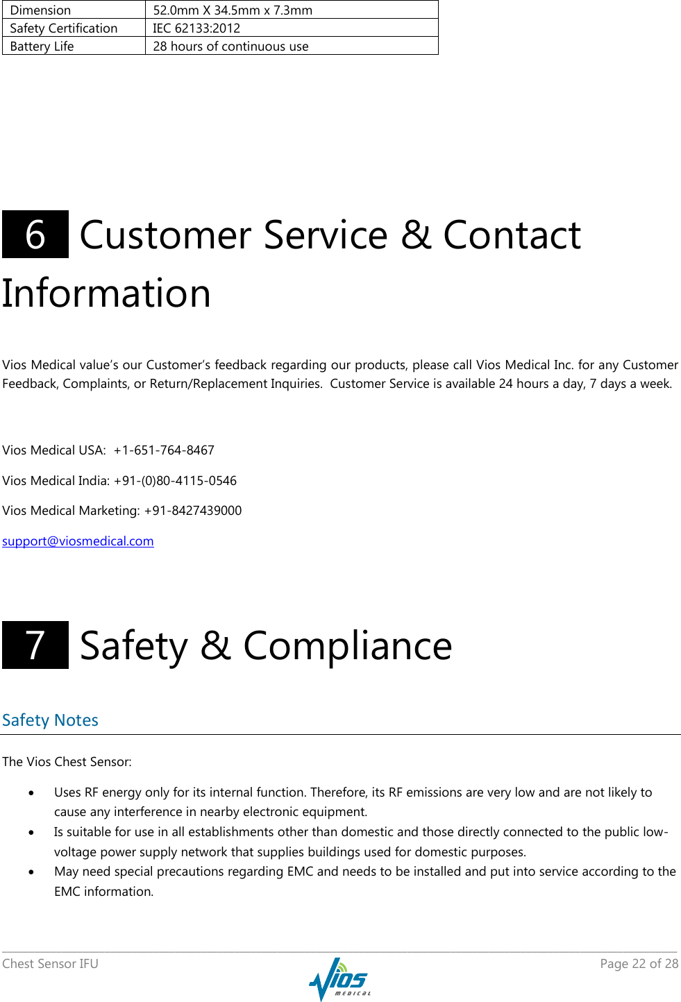
![_____________________________________________________________________________________________________________________________ Chest Sensor IFU Page 26 of 28 Conducted RF EN 61000-4-6 Radiated RF EN 61000-4-3 3 Vrms 150 kHz to 80 MHz 3 V/m 80 MHz to 2,5 GHz 3 Vrms 3 V/m Portable and mobile RF communications equipment should be used no closer to any part of the CS2050, including cables, than the recommended separation distance calculated from the equation applicable to the frequency of the transmitter. Recommended separation distance PVd ]1/5,3[ PEd ]1/5,3[ 80 MHz to 800 MHz PEd ]1/7[ 800 MHz to 2,5 GHz where P is the maximum output power rating of the transmitter in watts (W) according to the transmitter manufacturer and d is the recommended separation distance in meters (m). Field strengths from fixed RF transmitters, as determined by an electromagnetic site survey,a should be less than the compliance level in each frequency range.b Interference may occur in the vicinity of equipment marked with the following symbol: NOTE 1 At 80 MHz and 800 MHz, the higher frequency range applies. NOTE 2 These guidelines may not apply in all situations. Electromagnetic propagation is affected by absorption and reflection from structures, objects and people. a Field strengths from fixed transmitters, such as base stations for radio (cellular/cordless) telephones and land mobile radios, amateur radio, AM and FM radio broadcast and TV broadcast cannot be predicted theoretically with accuracy. To assess the electromagnetic environment due to fixed RF transmitters, an electromagnetic site survey should be considered. If the measured field strength in the location in which the CS2050 is used exceeds the applicable RF compliance level above, the CS2050 should be observed to verify normal operation. If abnormal performance is observed, additional measures may be necessary, such as reorienting or relocating the CS2050. b Over the frequency range 150 kHz to 80 MHz, field strengths should be less than 3 V/m. Table D: Recommended separation distances between portable and mobile RF communications equipment and the medical electrical equipment and medical electrical systems – for medical electrical equipment and medical electrical systems that are not life-supporting Recommended separation distances between portable and mobile RF communications equipment and the CS2050](https://usermanual.wiki/Vios-Medical/CS2050/User-Guide-3583932-Page-26.png)
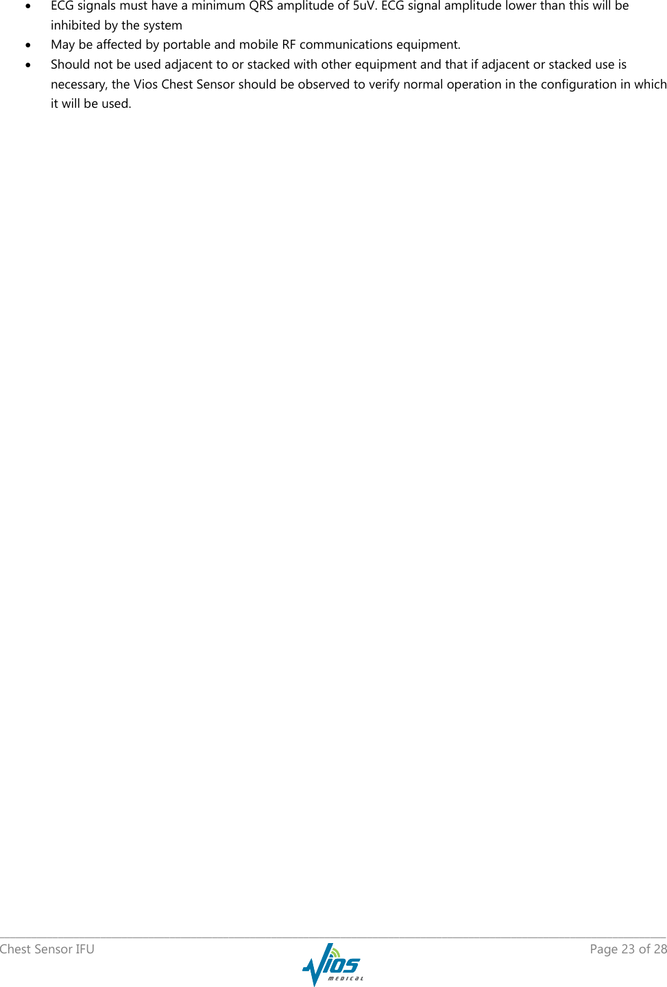
![_____________________________________________________________________________________________________________________________ Chest Sensor IFU Page 27 of 28 The CS2050 is intended for use in an electromagnetic environment in which radiated RF disturbances are controlled. The customer or the user of the CS2050 can help prevent electromagnetic interference by maintaining a minimum distance between portable and mobile RF communications equipment (transmitters) and the CS2050 as recommended below, according to the maximum output power of the communications equipment. Rated maximum output power of transmitter W Separation distance according to frequency of transmitter m 150 kHz to 80 MHz PVd ]1/5,3[ 80 MHz to 800 MHz PEd ]1/5,3[ 800 MHz to 2,5 GHz PEd ]1/7[ 0,01 0,12 0,12 0,23 0,1 0,38 0,38 0,73 1 1,2 1,2 2,3 10 3,8 3,8 7,3 100 12 12 23 For transmitters rated at a maximum output power not listed above, the recommended separation distance d in meters (m) can be estimated using the equation applicable to the frequency of the transmitter, where P is the maximum output power rating of the transmitter in watts (W) according to the transmitter manufacturer. NOTE 1 At 80 MHz and 800 MHz, the separation distance for the higher frequency range applies. NOTE 2 These guidelines may not apply in all situations. Electromagnetic propagation is affected by absorption and reflection from structures, objects and people. The Vios Monitoring System (VMS) has been designed in compliance with applicable Safety Standards given below. Vios™ is a trademark of Vios Medical Incorporated. Safety Standards 60601-1: Safety Requirements for Medical Electrical Systems 60601-1-2: General Requirements for Safety – Electromagnetic Compatibility 60601-2-27: Particular requirements for the basic safety and essential performance of electrocardiographic monitoring equipment 60601-2-49: Particular requirements for the safety of Multifunction Patient Monitoring Equipment ISO 80601-2-61: Particular requirements for basic safety and essential performance of pulse oximeter equipment ISO 10993-1: Biological Evaluation of medical devices EN 300 328 v1.8.1, Electromagnetic compatibility and Radio spectrum Matters (ERM); Wideband transmission systems; Data transmission equipment operating in the 2,4 GHz ISM band and using wide band modulation techniques ASTM D4169-14: Standard Practice for Performance Testing of Shipping Containers and Systems IEC 60529 standard Ingress Protection Marking – IP22 EC53 ECG Trunk Cables and Patient Leadwires](https://usermanual.wiki/Vios-Medical/CS2050/User-Guide-3583932-Page-27.png)