Vytek PTX-150 Digital Paging Transmitter User Manual PTX 150
Vytek Inc Digital Paging Transmitter PTX 150
UserManual.wiki
>
Vytek
>
PTX-150 User Manual
>
manual
Contents
1.
User Manual MNTPTX150
2.
manual
manual
Navigation menu
Upload a User Manual
Namespaces
Wiki Guide
HTML
PDF
Info
Views
User Manual
Discussion / Help
Navigation
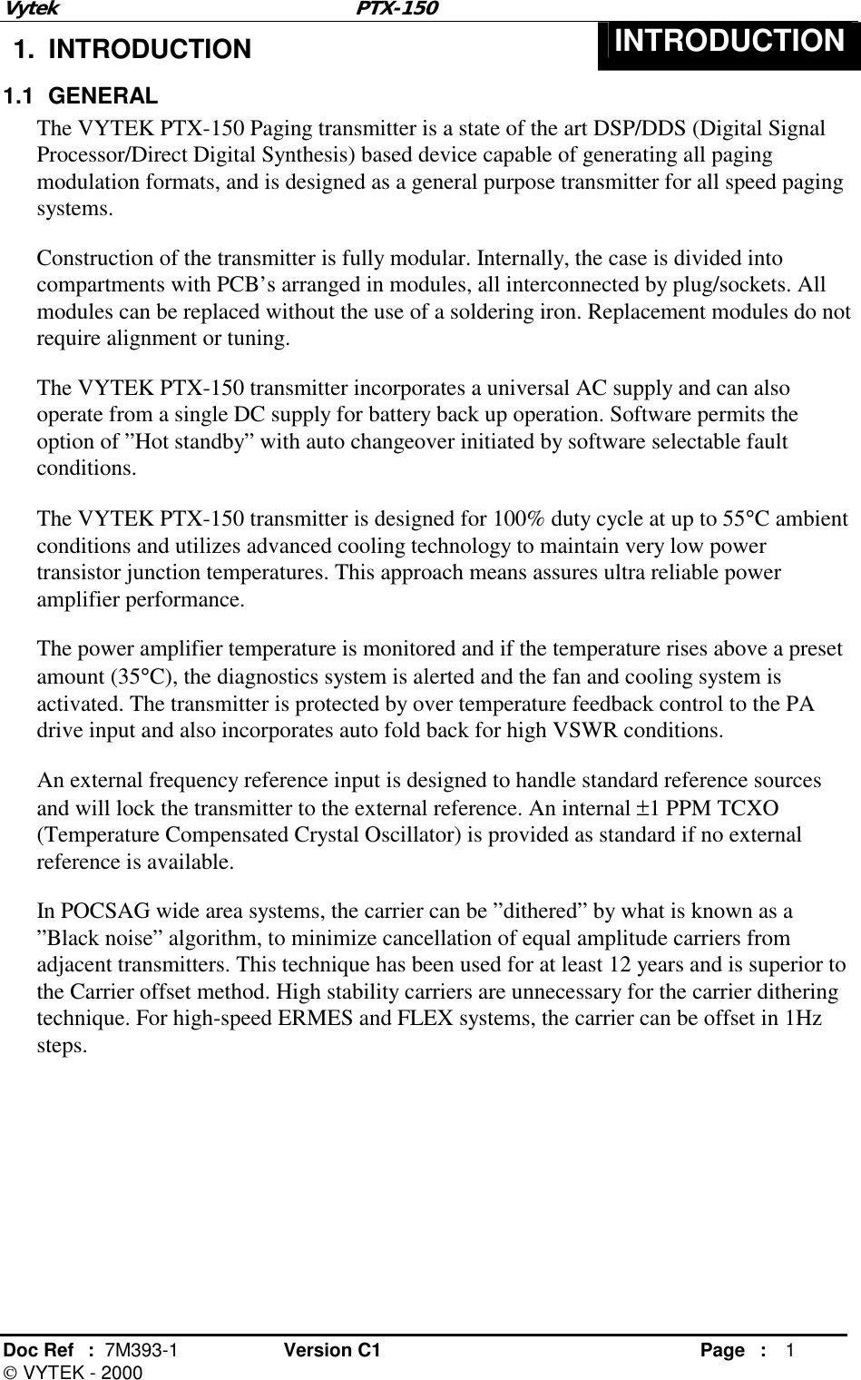
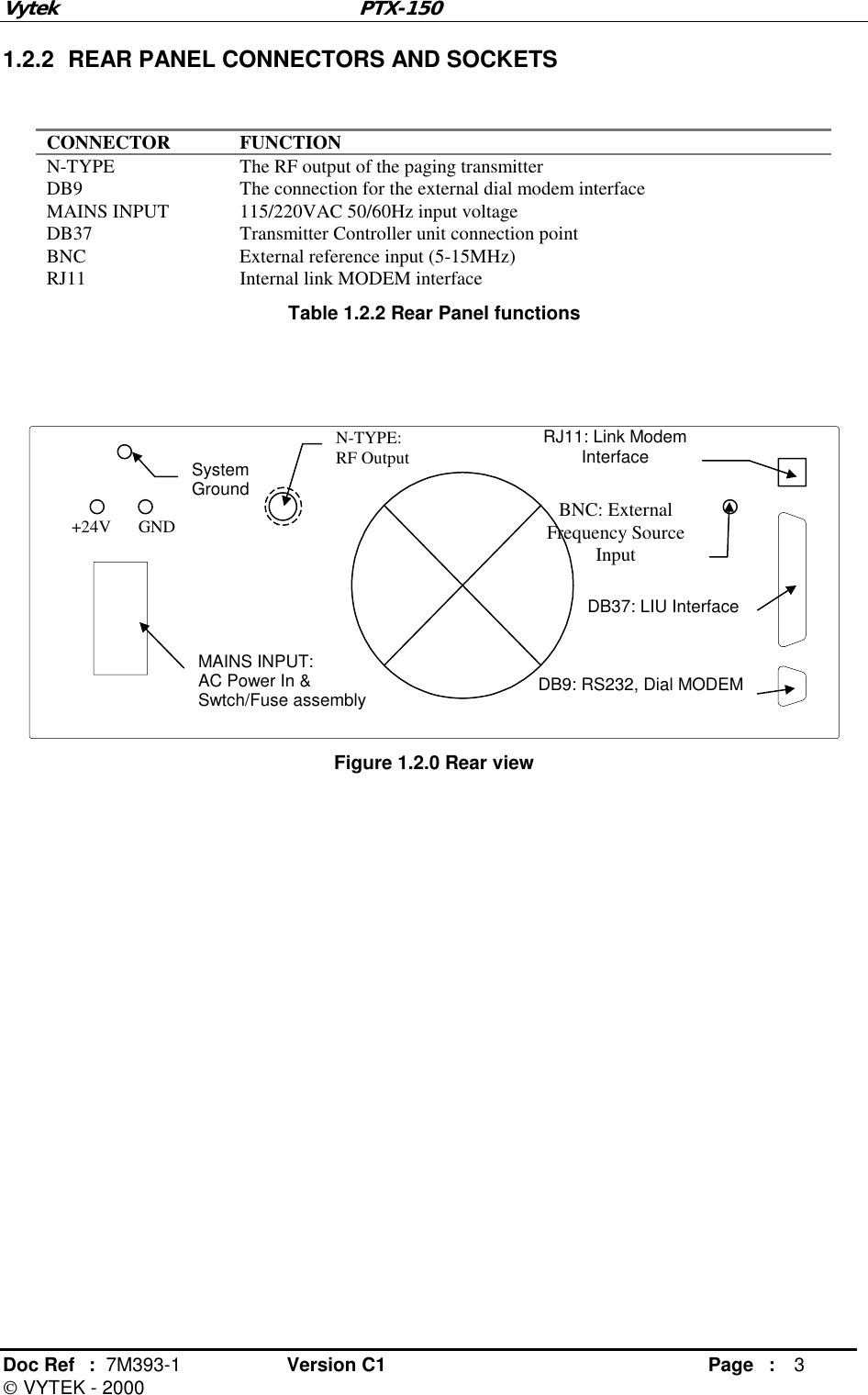
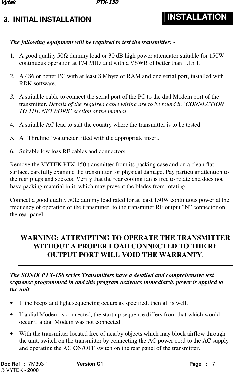
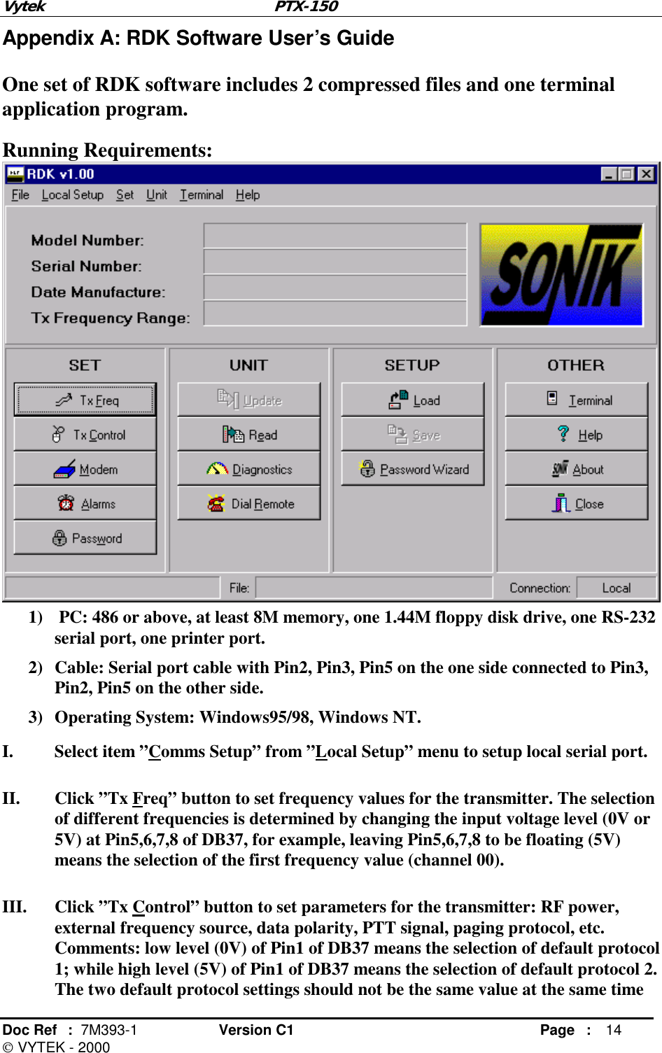
![Vytek PTX-150 Doc Ref : 7M393-1 Version C1 Page : 9 VYTEK - 2000 4. CONNECTION TO NETWORK CONNECTION Once the transmitter has been configured for the network, it is now necessary to install the unit into the station and interface to the LIU (Line Interface Unit). • Verify that the antenna lead is connected to the station antenna. Install a Thruline Wattmeter in series with the transmitter and antenna lead. • If a PSTN connection and dial Modem are available, install the dial modem and connect it to the dial Modem port (on the rear of the transmitter). Use a standard DCE to DTE RS232 interface cable (usually supplied with the dial modem). • If an external frequency reference is used, select that option in software and connect the source via a 50Ω coaxial cable and BNC male plug to the BNC socket at the rear of the transmitter. • Identify the appropriate data, clock and mode control connections from the LIU and connect them to the appropriate pins on the DB37 connector at the rear of the transmitter. The correct connections will vary depending upon the LIU used and the mode of operation. Refer to Table 4.0.1 of pin outs for the DB37 connector. PIN No. LIU Name FUNCTION 1 PR0 Protocol select line 5 CH4 Frequency select line 6 CH3 Frequency select line 7 CH2 Frequency select line 8 CH1 Frequency select line 11 KEY Transmitter key 15 LB TX DATA, TTL (L-Bit) 16 HB TX DATA, TTL (H-Bit, 4-level) 18 CLK Clock for synchronization data 19 GND Ground 21 ALM10 Reflected power alarm 2 (not used) 22 ALM11 Output power high alarm 23 ALM12 Output power alarm 2 (not used) 26 ALM3 TX Synthesizer alarm 29 ALM6 Output power low alarm 1 30 ALM7 Reflected power alarm 1 31 ALM8 Fan alarm Table 4.0.1 List of the DB37 connector pins. • Determine if PTT control is via the DB37 connector or will have to be automatic upon the detection of data. • If desired, check the setting for the transmitter Hang Time (time that transmitter stays keyed on after the last data transition has occurred on the TX DATA TTL [Lbit] pin). This function can be altered in software. • Connect AC power to the transmitter and note that the appropriate test cycle occurs. The transmitter is now ready to operate.](https://usermanual.wiki/Vytek/PTX-150.manual/User-Guide-333056-Page-11.png)
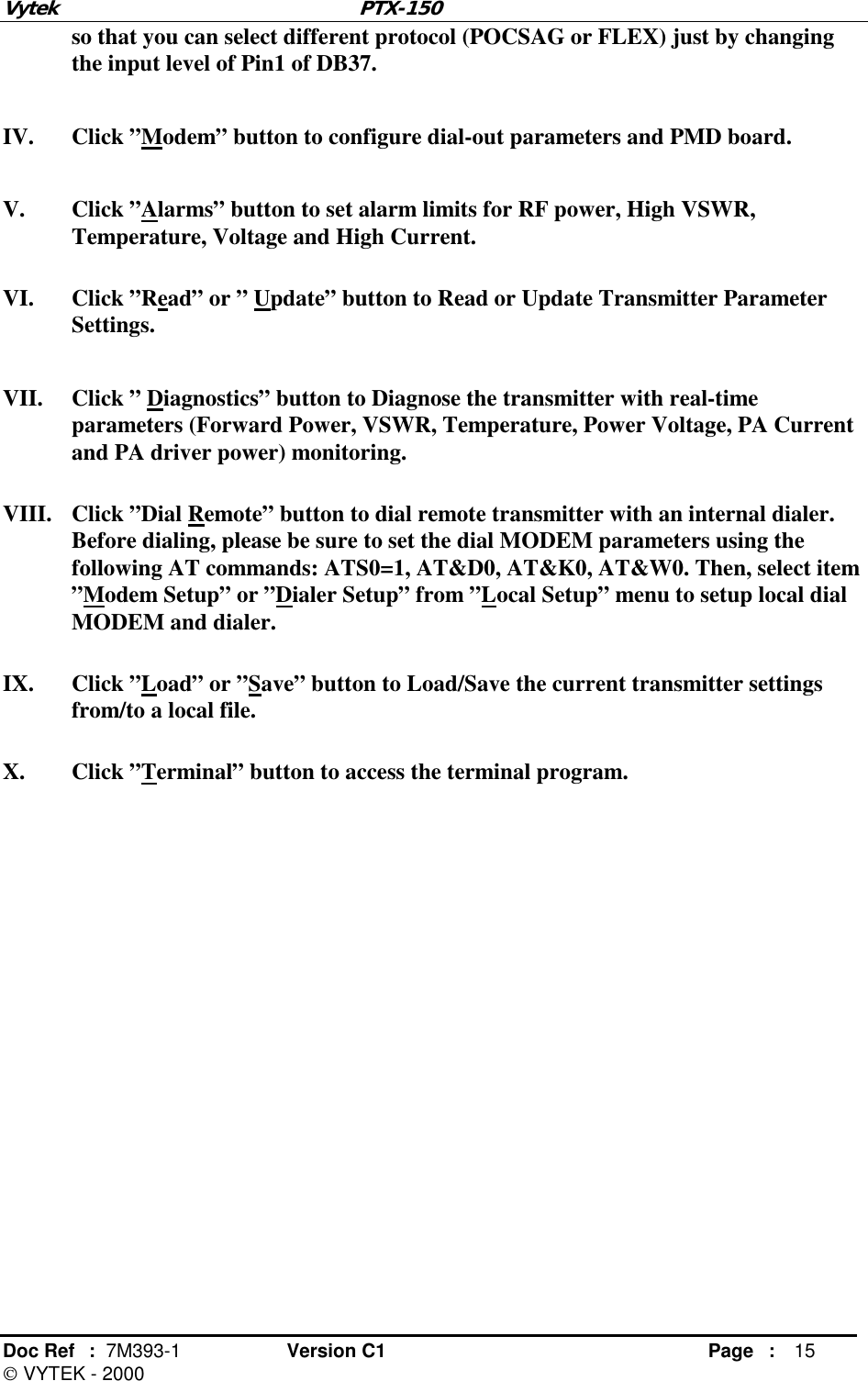
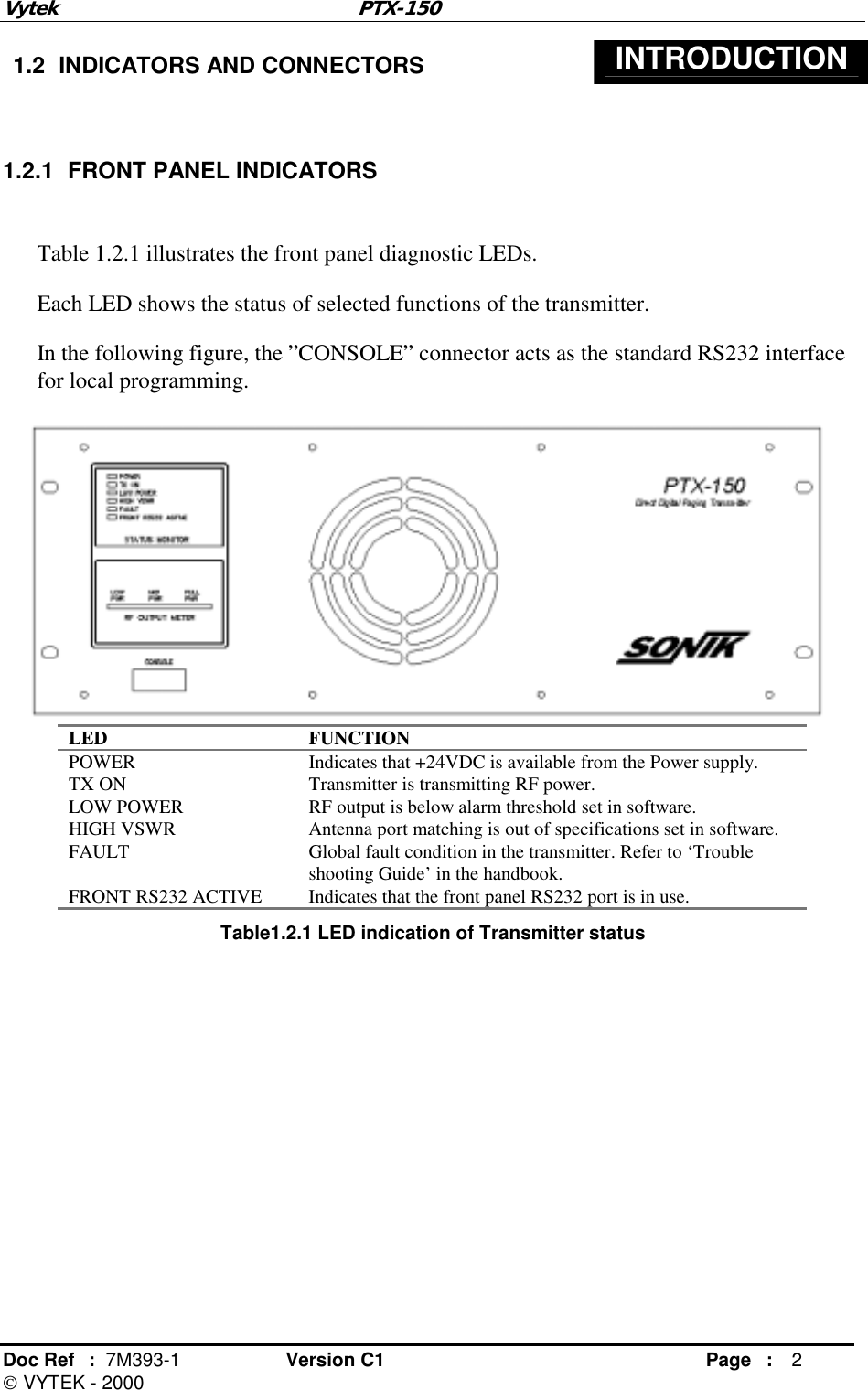
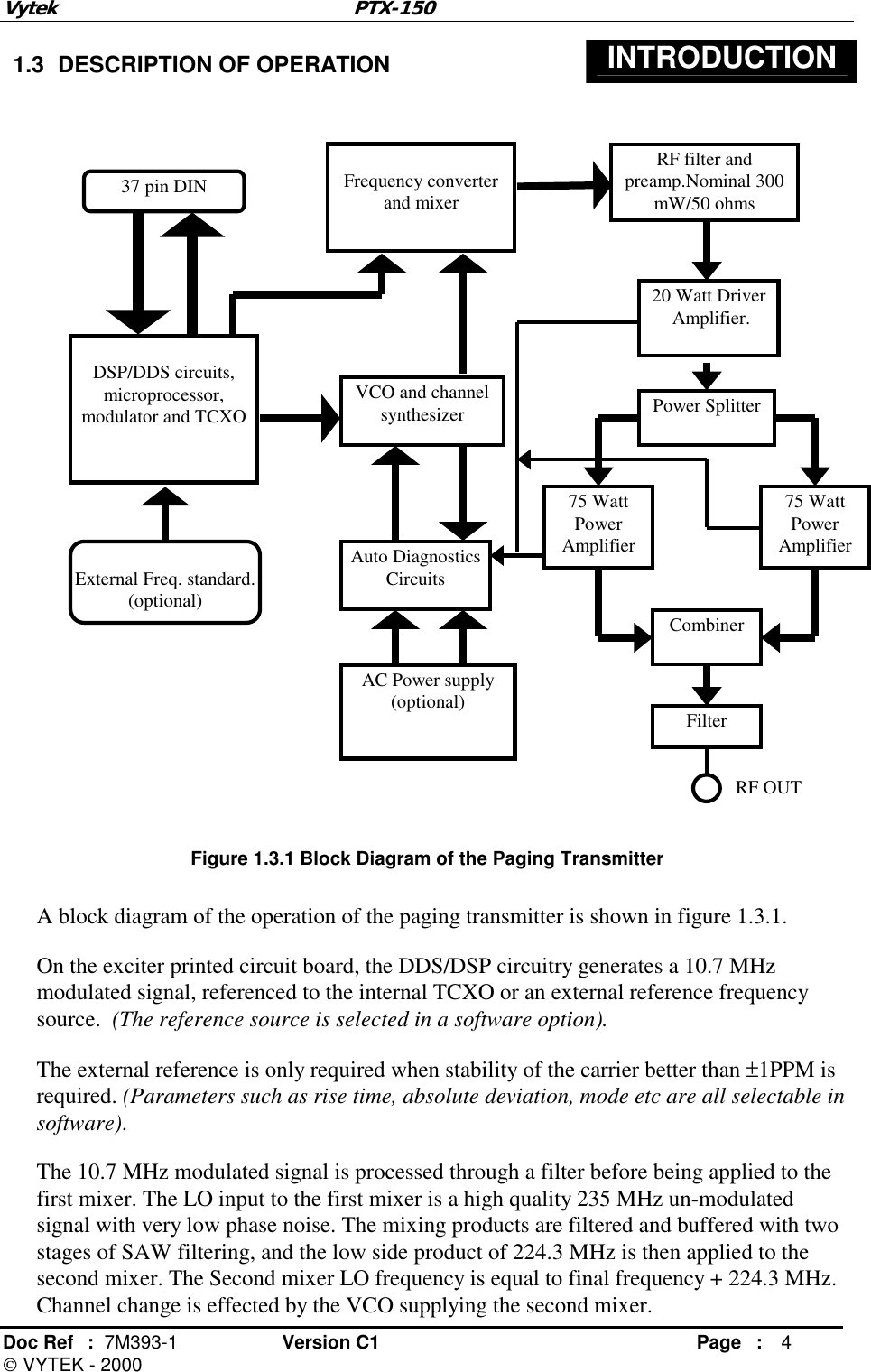
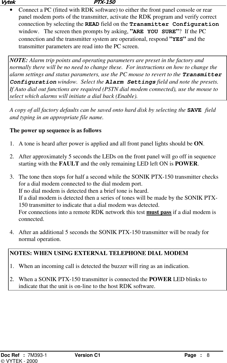
![Vytek PTX-150 Doc Ref : 7M393-1 Version C1 Page : 19 VYTEK - 2000 Appendix C: Satellite Link Mode Configuration for External NIU I. Connection between External NIU and SONIK PTX-150 transmitter: ! Connect the DATA, GND and CLK output signal of satellite receiver to TB1-5(Rx Data), TB1-4(GND) and TB1-6(Rx CLK) of External NIU. II. Jumper settings of External NIU: ! S15 Pin 1 is set to be ON. Others remain intact. III. Software configuration for External NIU: ! The serial port settings are: COM1, 19200bps, N, 8, 1. [ 0] NIU> set link ↵ ; Link settings link = fm2 @ 9600 from digital_in [ 0] NIU> set align_type ↵ ; Synchronization mode GPS Mode: Alignment type is gps No GPS Mode: Alignment type is dir_sync [ 0] NIU> config devid ↵ ; Base station device ID. [ 0] NIU> config sysid ↵ ; System ID. [ 0] NIU> config txd ↵ ; Paging data polarity. [ 0] NIU> set maint_polarity ↵ ; Maintenance cycle polarity. [ 0] NIU> show gps ↵ ; At GPS mode, display current GPS settings. [ 0] NIU> show status ↵ ; Display current External NIU status. [ 0] NIU> show alarm ↵ ; Display alarms for External NIU. [ 0] NIU> show config ↵ ; Display current NIU system parameters. [ 0] NIU> show dipsw ↵ ; Display current NIU jumper settings.](https://usermanual.wiki/Vytek/PTX-150.manual/User-Guide-333056-Page-21.png)