WJ Communications SR320 RFID Tag Reader User Manual MPR5000 User s Manual Draft
WJ Communications, Inc. RFID Tag Reader MPR5000 User s Manual Draft
UserManual.wiki
>
WJ Communications
>
SR320 User Manual
Users Manual
Navigation menu
Upload a User Manual
Namespaces
Wiki Guide
HTML
PDF
Info
Views
User Manual
Discussion / Help
Navigation
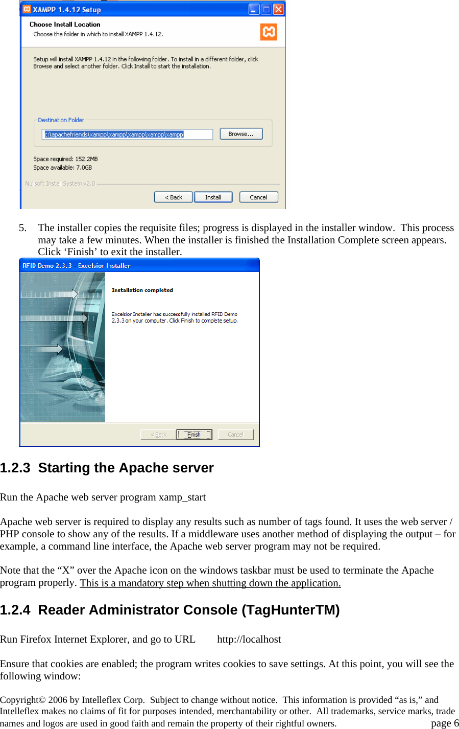
![1.3 Host-Reader Interface If you want to create your own software to communicate with and control stationary readers, see the document “Intelleflex Middleware Application Programming Interface” for communication with the reader using SLRRP based protocol over the Ethernet port. 1.4 Troubleshooting / technical support 1.5 Technical specifications Parameter Specification Operating Frequency US ISM band (902-928 MHz); frequency-hopping Protocol support EPCGlobal Class 1 Gen 2, Intelleflex Class 3 RF Transmit Power 1 Watt Tag Read Range 6 meters [20 feet] typical for C1G2, up to 100 m for C3 Antenna ports Up to 4 pairs of (Transmit/Receive); RP-TNC connectors Antenna Specifications cable attenuation higher than 1 dB Linear polarization antenna gain less than 7 dBil Reader modes Host initiation mode or autonomous operation based on timer or external trigger Host interface Serial control over RS232, or TCP/IP over Ethernet; SLRRP based API Operating temperature 0 to 50°C (32 to 122°F) Storage temperature -20 to 70°C (-4 to 158°F) Power supply 24 VDC, 2.7 A FCC certification FCC part 15 unlicensed operation [PENDING AT TIME OF WRITING] 1.6 Notices 1.6.1 RFID limitations Communication between tags and readers at UHF frequencies is a complex phenomenon depending on details of the environment surrounding the tags and reader(s) as well as the equipment being used. Some environmental aspects (such as tag placement and orientation) may be controllable by the user; others (such as reflections of the RF radiation by ambient objects) are generally not. Careful installation and testing, and development and adherence to appropriate operating procedures, are indispensable for successful implementation of RFID. Intelleflex. makes no representation or warrantee that any specific configuration of RFID tags and readers will provide any given performance characteristics. 1.6.2 Safety Any use of this equipment with antennas or cabling installed outdoors or otherwise exposed to inclement weather must avoid proximity with power lines or other high-voltage conductors, and provide for proper grounding and lightning arresting devices to protect the equipment user in the event of a lightning strike. See National Electrical Code (NEC) requirements articles 725, 800, and 810 for further information. Copyright© 2006 by Intelleflex Corp. Subject to change without notice. This information is provided “as is,” and Intelleflex makes no claims of fit for purposes intended, merchantability or other. All trademarks, service marks, trade names and logos are used in good faith and remain the property of their rightful owners. page 22](https://usermanual.wiki/WJ-Communications/SR320/User-Guide-672757-Page-22.png)
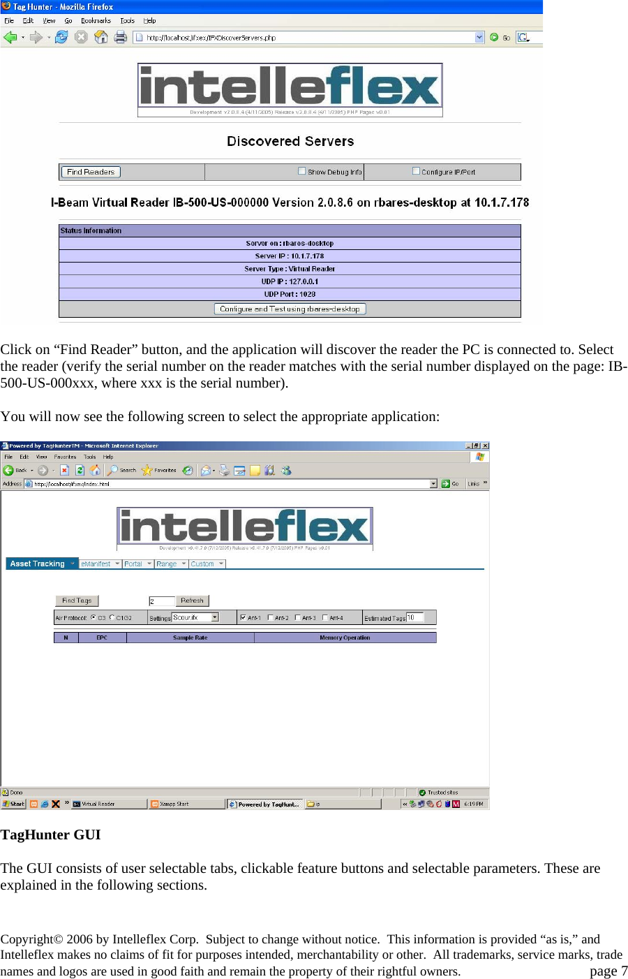
![Do not operate the stationary readers in any area where critical safety equipment may be sensitive to RF interference, such as medical or life support equipment. Do not operate the stationary readers on board any aircraft in flight, or at any other time when operation of radio devices such as cellular phones is prohibited. Personnel should not be closer than 23 cm (9 inches) from any Stationary reader antenna for prolonged periods of time. See FCC bulletins 56 and 65 for further information on electromagnetic field exposure. 1.6.3 Limitation of liability The information in this manual is subject to change without notice and does not represent a commitment on the part of Intelleflex. Intelleflex specifically disclaims liability for any and all direct, indirect, special, general, incidental, consequential, punitive or exemplary damages, including but not limited to loss of profits, revenue, or anticipated loss of profits or revenue, arising out of the use or inability to use any Intelleflex. product, even if Intelleflex has been advised or the possibility of such damages or they are foreseeable, or for claims by any third party. 1.6.4 Patents Portions of the products described in this manual may be covered by granted or currently-pending US and foreign patents. 1.6.5 Copyright notice The contents of this document are the property of Intelleflex, except where otherwise noted. Individuals who have purchased or otherwise legally acquired the stationary reader hardware units described in this document are expressly permitted to make copies of the document, in electronic or paper form, for personal, backup, and archival use. Brief segments may be excerpted and used with attribution for descriptive purposes in commentaries, reviews, or other informational documents. All other reproduction in whole or in part is expressly prohibited without the consent of the copyright owner. Copyright 2006 by Intelleflex. 1.6.6 Comments and feedback Comments and feedback on this manual or the stationary readers are welcomed: By phone: 1-408-350-6101 By email: info@intelleflex.comBy physical mail: Intelleflex Corp. 1075 E. Brokaw Road, Suite 200 San Jose, CA 95131. USA 1.7 Regulatory Compliance 1.7.1 FCC Statement This equipment has been tested [PENDING AT THE TIME OF THIS WRITING!] and found to comply with Part 15 of the FCC Rules. These limits are designed to provide reasonable protection against harmful interference in a residential installation. This equipment generates, uses and can radiate radio frequency energy and, if not installed and used in accordance with the instructions, may cause harmful interference to radio communications. However, there is no guarantee that Copyright© 2006 by Intelleflex Corp. Subject to change without notice. This information is provided “as is,” and Intelleflex makes no claims of fit for purposes intended, merchantability or other. All trademarks, service marks, trade names and logos are used in good faith and remain the property of their rightful owners. page 23](https://usermanual.wiki/WJ-Communications/SR320/User-Guide-672757-Page-23.png)