WOORIRO WDR300 24GHz micro Doppler Radar User Manual
WOORIRO CO., LTD. 24GHz micro Doppler Radar
UserManual.wiki
>
WOORIRO
>
WDR300 User Manual
User Manual
Navigation menu
Upload a User Manual
Namespaces
Wiki Guide
HTML
PDF
Info
Views
User Manual
Discussion / Help
Navigation
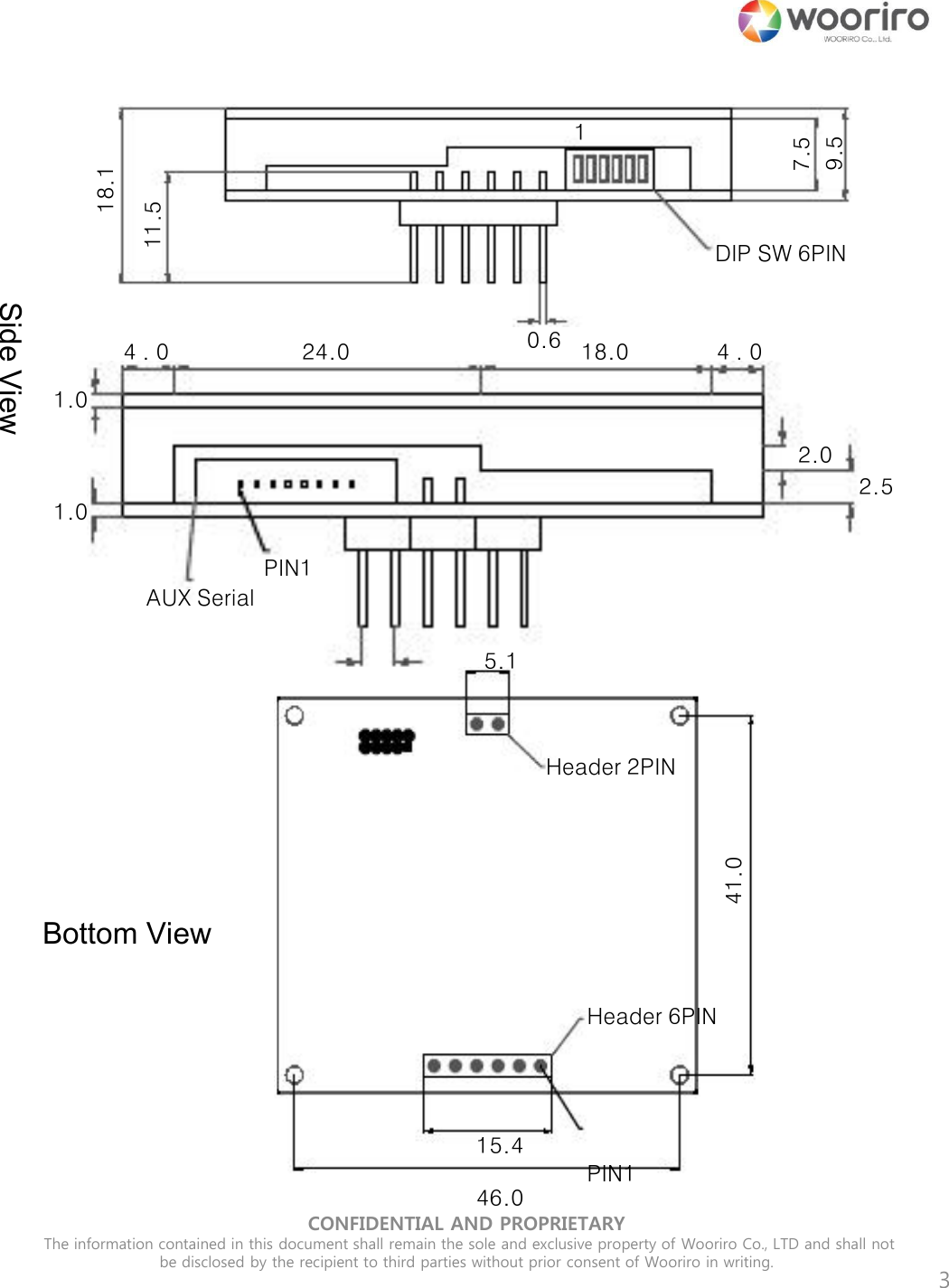
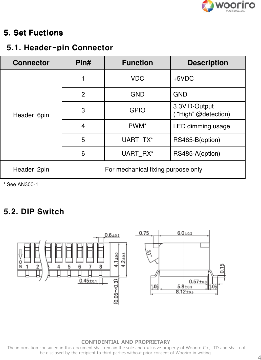
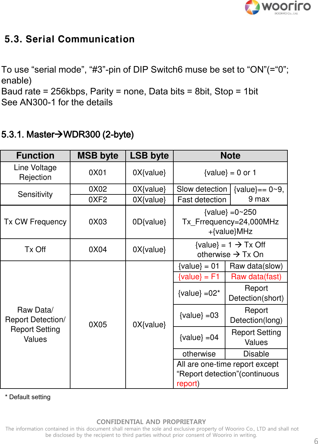
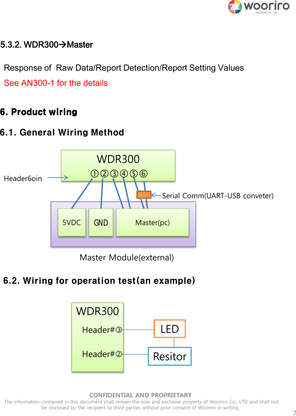
![5 5.2. DIP Switch Function \ Pin# #6 #5 #4 #3 #2 #1 Line-voltage rejection 50Hz 0 60Hz () 1 Sensitivity Max -3 0 0 Max-2 0 1 Max-1 1 0 Max (default) 1 1 Serial Communication Enable 0 Disable (default) 1 Tx CW Frequency Low 0 0 Medium 0 1 High 1 0 Default 1 1 Note : “0”=“ON” and “1”=“OFF” Fuction Frequency [GHz] Tx CW Frequency Low 24.07 +/- 0.01 Medium 24.125 +/- 0.01 High 24.23 +/- 0.01 Default 24.17 +/- 0.01 CONFIDENTIAL AND PROPRIETARY The information contained in this document shall remain the sole and exclusive property of Wooriro Co., LTD and shall not be disclosed by the recipient to third parties without prior consent of Wooriro in writing.](https://usermanual.wiki/WOORIRO/WDR300/User-Guide-3527854-Page-5.png)
![CONFIDENTIAL AND PROPRIETARY The information contained in this document shall remain the sole and exclusive property of Wooriro Co., LTD and shall not be disclosed by the recipient to third parties without prior consent of Wooriro in writing. 10 CE Statement For MPE Statement – Mobile device This equipment complies with EU radiation exposure limits set forth for an uncontrolled environment. This equipment should be installed and operated with minimum distance 20cm between the radiator & your body. All operational modes Operational mode: 24GHz radar detection The frequency and the maximum transmitted power in EU are listed below: 24.07GHz~24.23GHz : 11.40 dBm Hereby , [WOORIRO Co., Ltd.] declares that the radio equipment type [WDR300] is in compliance with Directive 2014/53/EU. The full text of the EU declaration of conformity is available at the following internet address: www.wooriro.com](https://usermanual.wiki/WOORIRO/WDR300/User-Guide-3527854-Page-12.png)