Wanlida Group PG74303GCMC Wireless Reversing Camera User Manual PG 74303 071011
Wanlida Group Co., Ltd. Wireless Reversing Camera PG 74303 071011
UserManual.wiki
>
Wanlida Group
>
PG74303GCMC User Manual
Users Manual
Navigation menu
Upload a User Manual
Namespaces
Wiki Guide
HTML
PDF
Info
Views
User Manual
Discussion / Help
Navigation


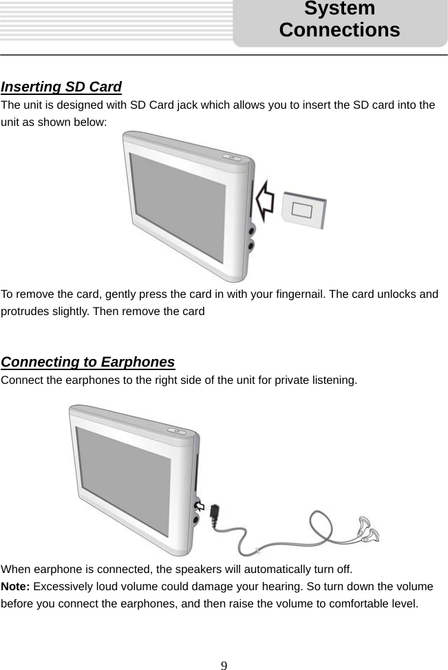
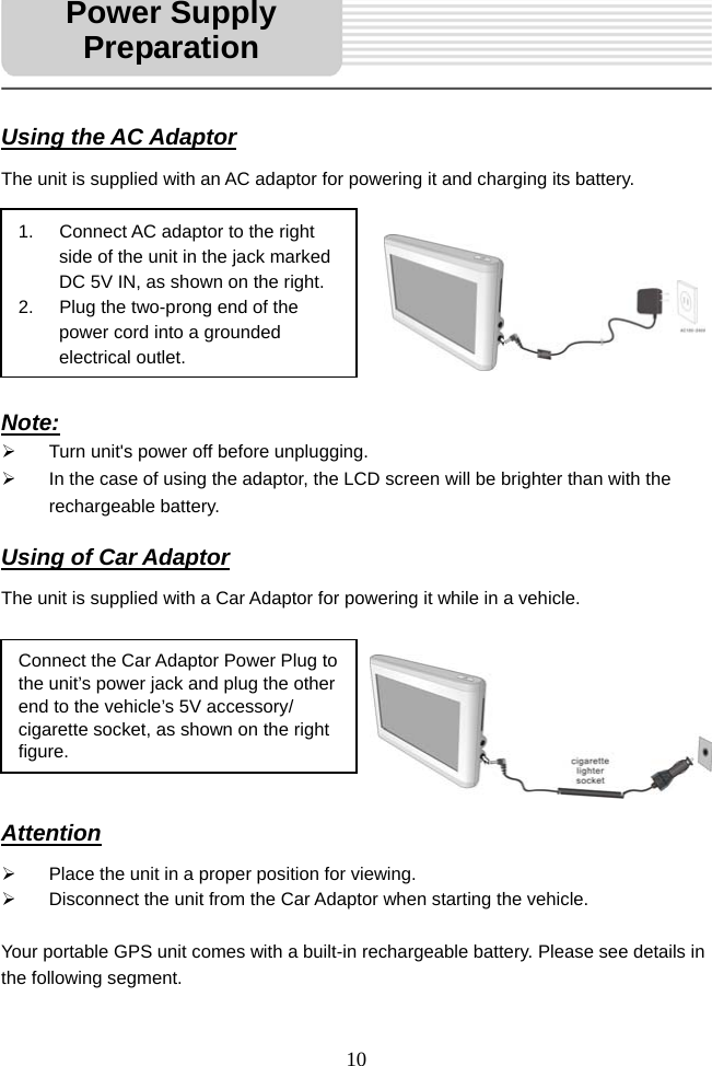
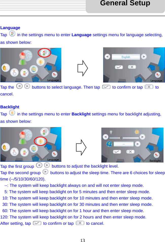
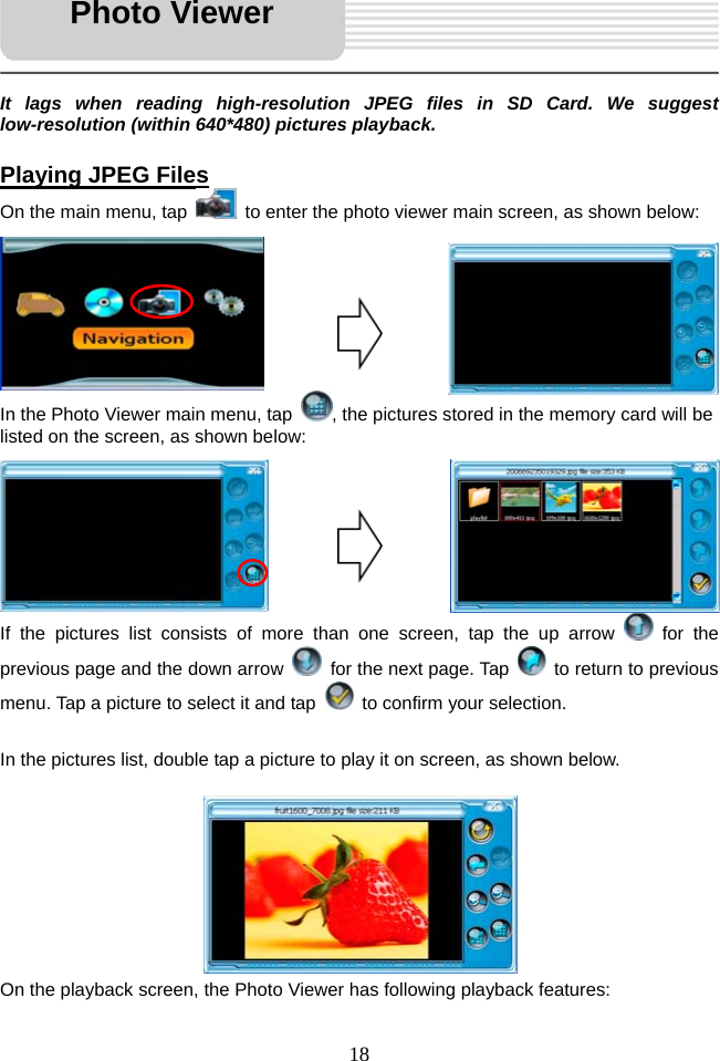
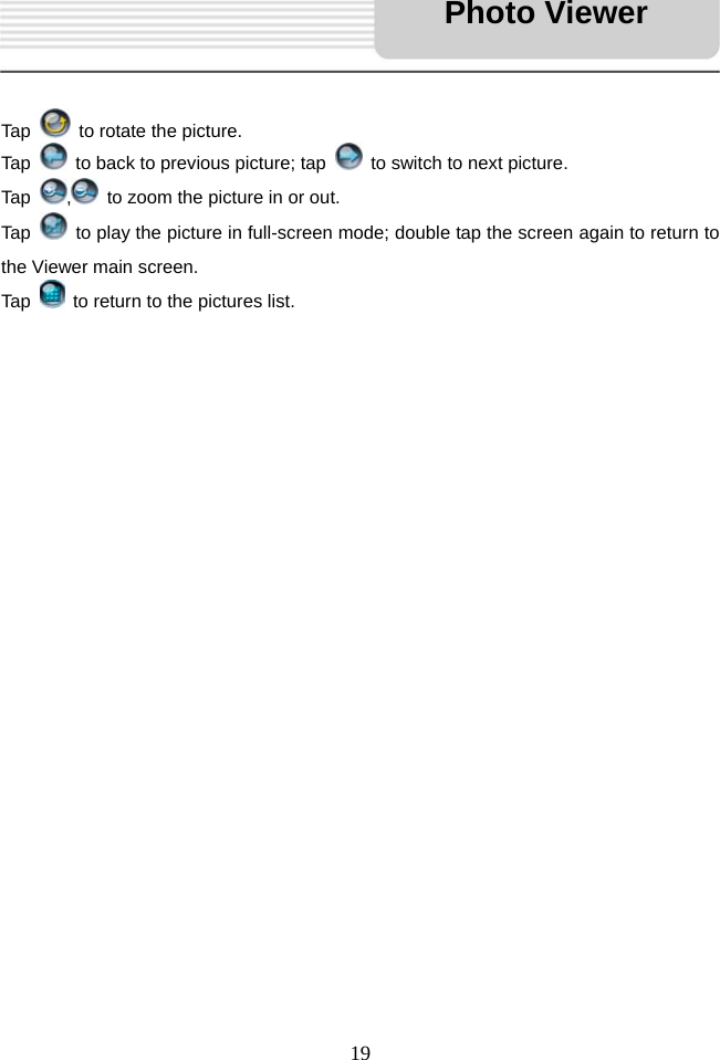
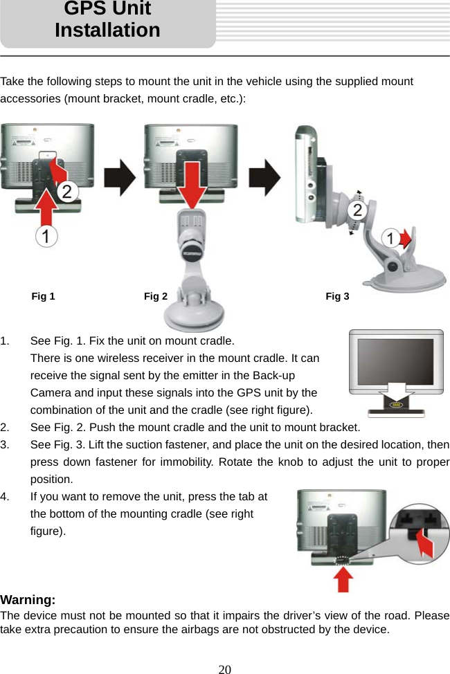
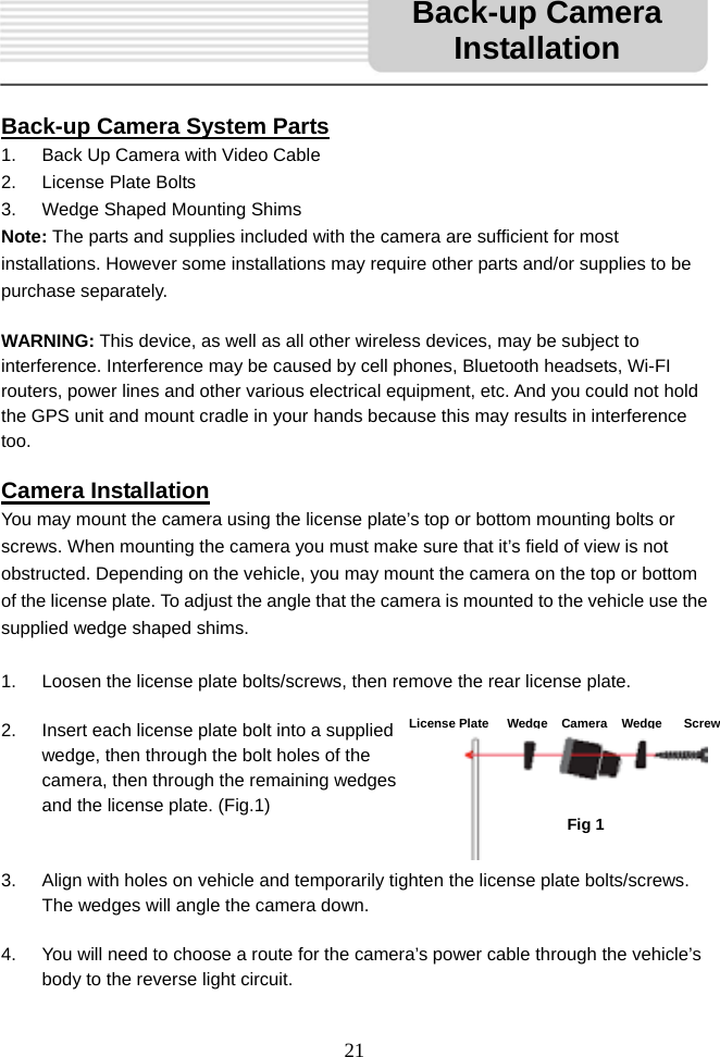
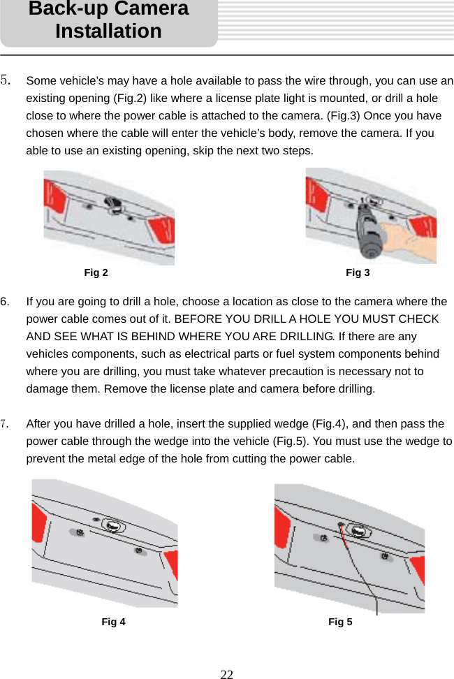
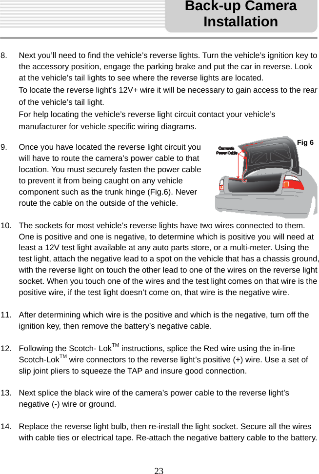
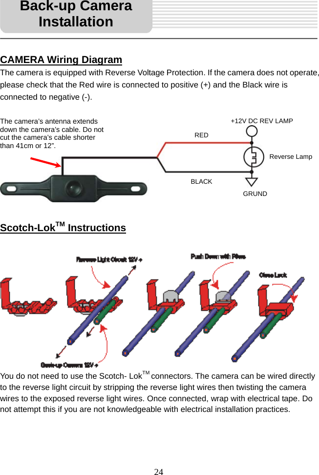
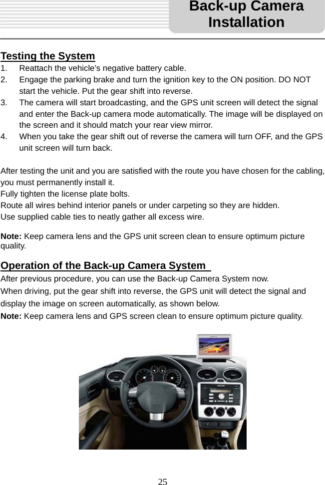
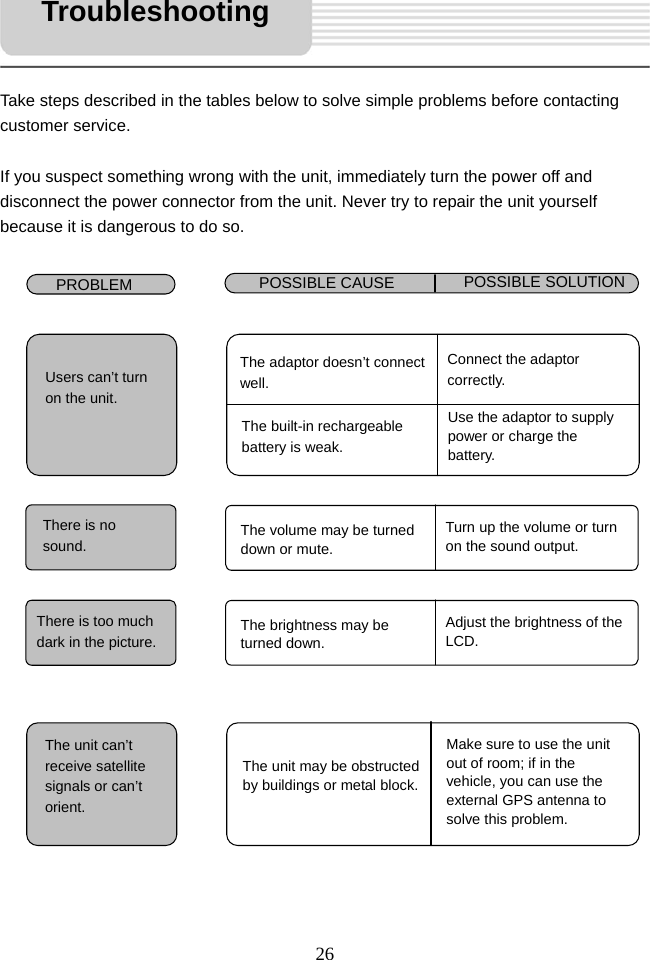
![3 Warning Failure to avoid the following potentially hazardous situations may result in injury or property damage. The unit is designed to provide you with route suggestions. It does not reflect road closures or road conditions, traffic congestion, weather conditions, or other factors that may affect safety or timing while driving. Use the unit only as a navigational aid. Do not attempt to use the unit for any purpose requiring precise measurement of direction, distance, location, or topography. This product should not be used to determine ground proximity for aircraft navigation. CAUTION: Danger of explosion if battery is incorrectly replaced. Replace only with the same or equivalent type. The batteries (or batteries installed) shall not be exposed to excessive heat such as sunshine, fire or the like. Underwriters Laboratories Inc. (“UL”) has not tested the performance or reliability of the Global Positioning System (“GPS”) hardware, operating software or other aspects of this product. UL has only tested for fire, shock or casualty hazards as outlined in UL’s Standard(s) for Safety [Note-Consider referencing specific UL standard]. UL Certification does not cover the performance or reliability of the GPS hardware and GPS operating software. UL MAKES NO REPRESENTATIONS, WARRANTIES OR CERTIFICATIONS WHATSOEVER REGARDING THE PERFORMANCE OR RELIABILITY OF ANY GPS RELATED FUNCTIONS OF THIS PRODUCT. This device complies with part 15 of the FCC Rules. Operation is subject to the following two conditions: (1) This device may not cause harmful interference, and (2) This device must accept any interference received, including interference that may cause undesired operation. Changes or modifications not expressly approved by the party responsible for compliance could void the user's authority to operate the Important Safety Instructions](https://usermanual.wiki/Wanlida-Group/PG74303GCMC/User-Guide-1018399-Page-3.png)