Wireless N2X5-3S1-16B User Manual Dec 17 draft pdf version
Wireless Inc Dec 17 draft pdf version
UserManual.wiki
>
Wireless
>
N2X5-3S1-16B User Manual
>
Dec 17 draft pdf version
Contents
1.
n2xusersMANUAL
2.
Manual update in response to 22 Nov information request
3.
Dec 17 draft pdf version
4.
Additional corrections to 17 Dec draft
5.
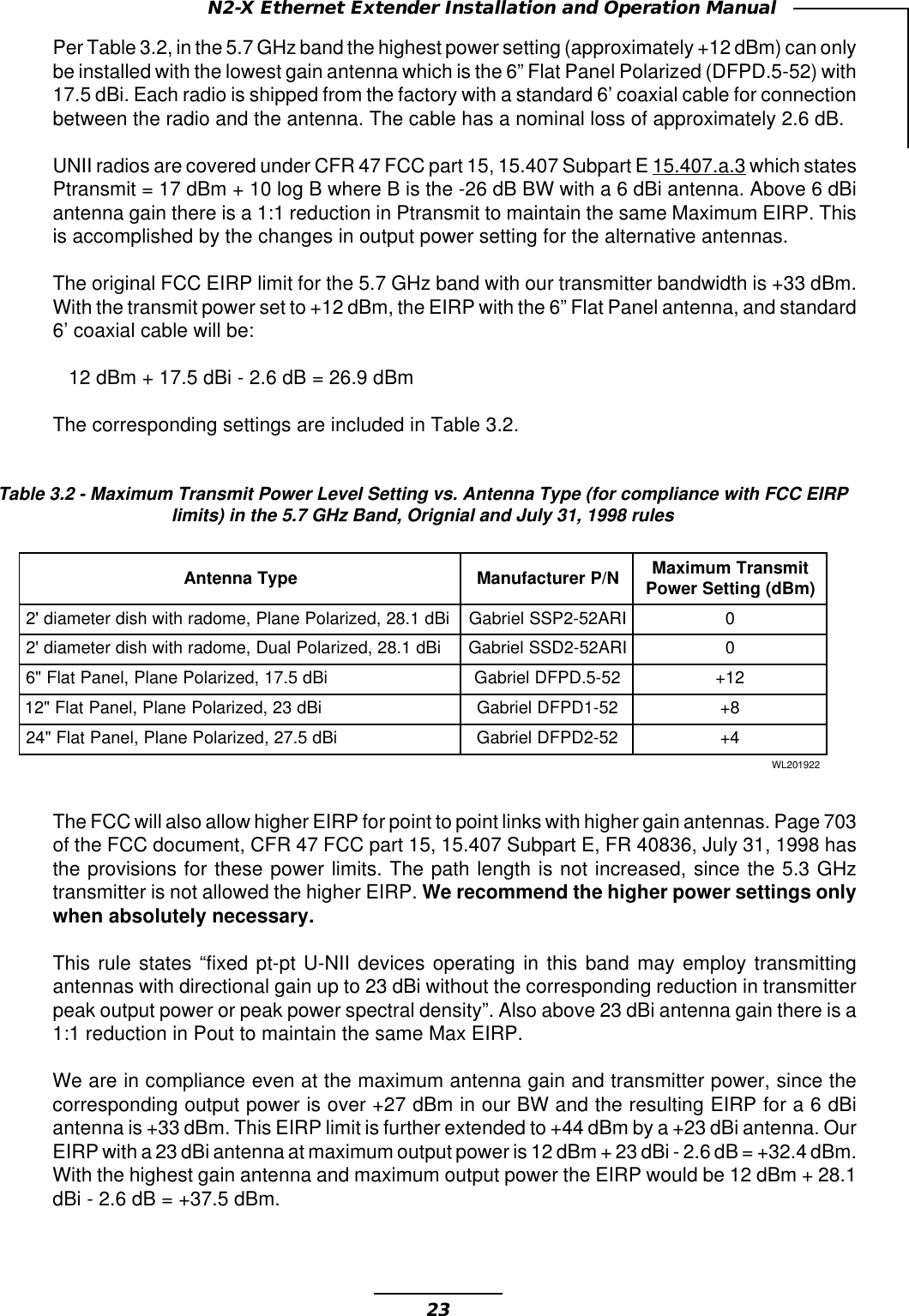
Gabriel flat panel antenna description
Dec 17 draft pdf version
Navigation menu
Upload a User Manual
Namespaces
Wiki Guide
HTML
PDF
Info
Views
User Manual
Discussion / Help
Navigation
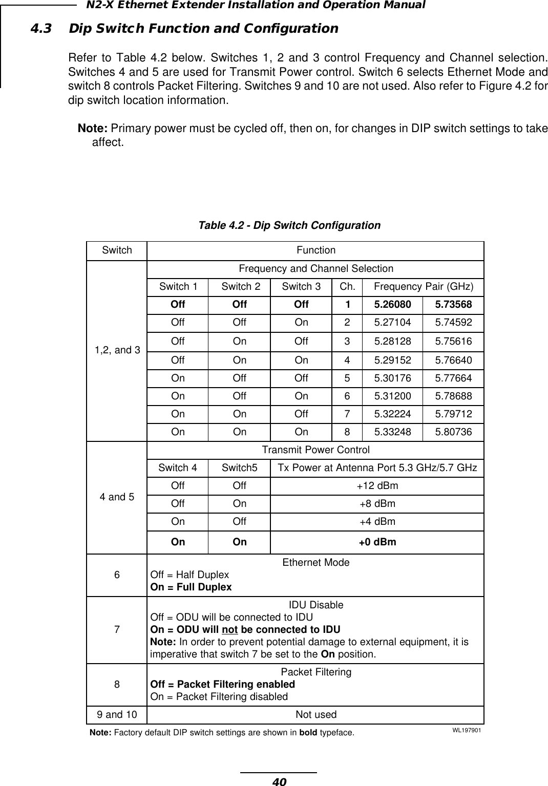
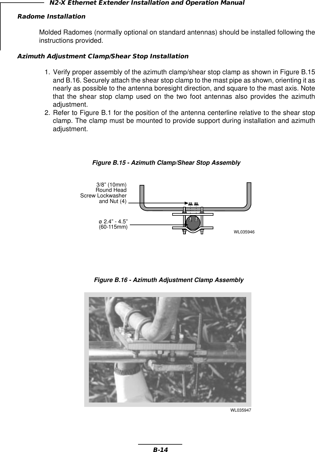
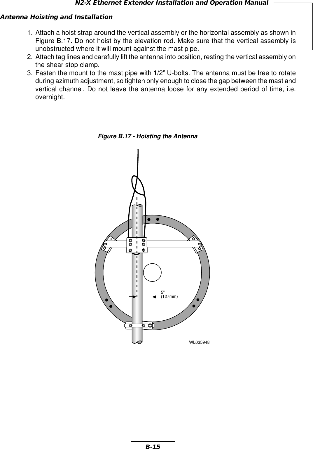
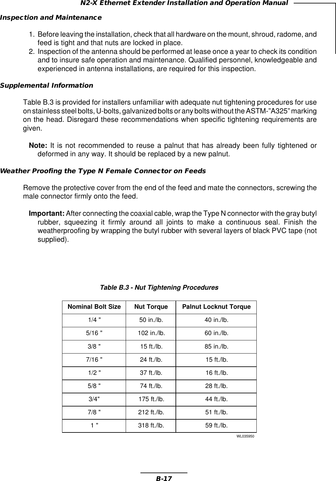
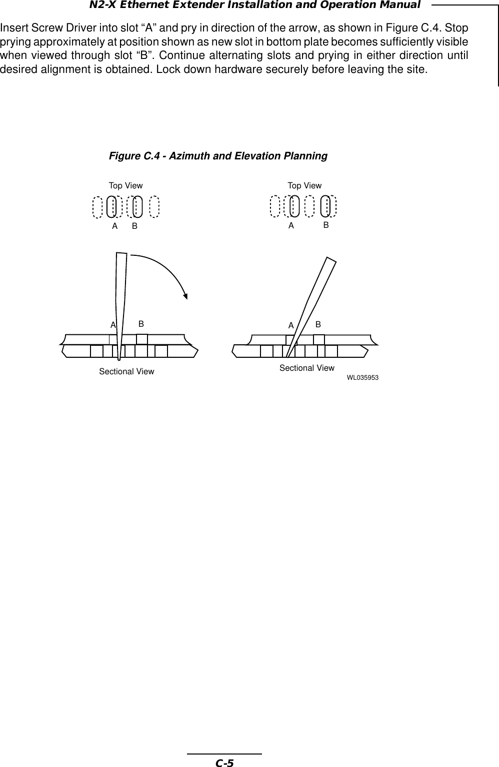
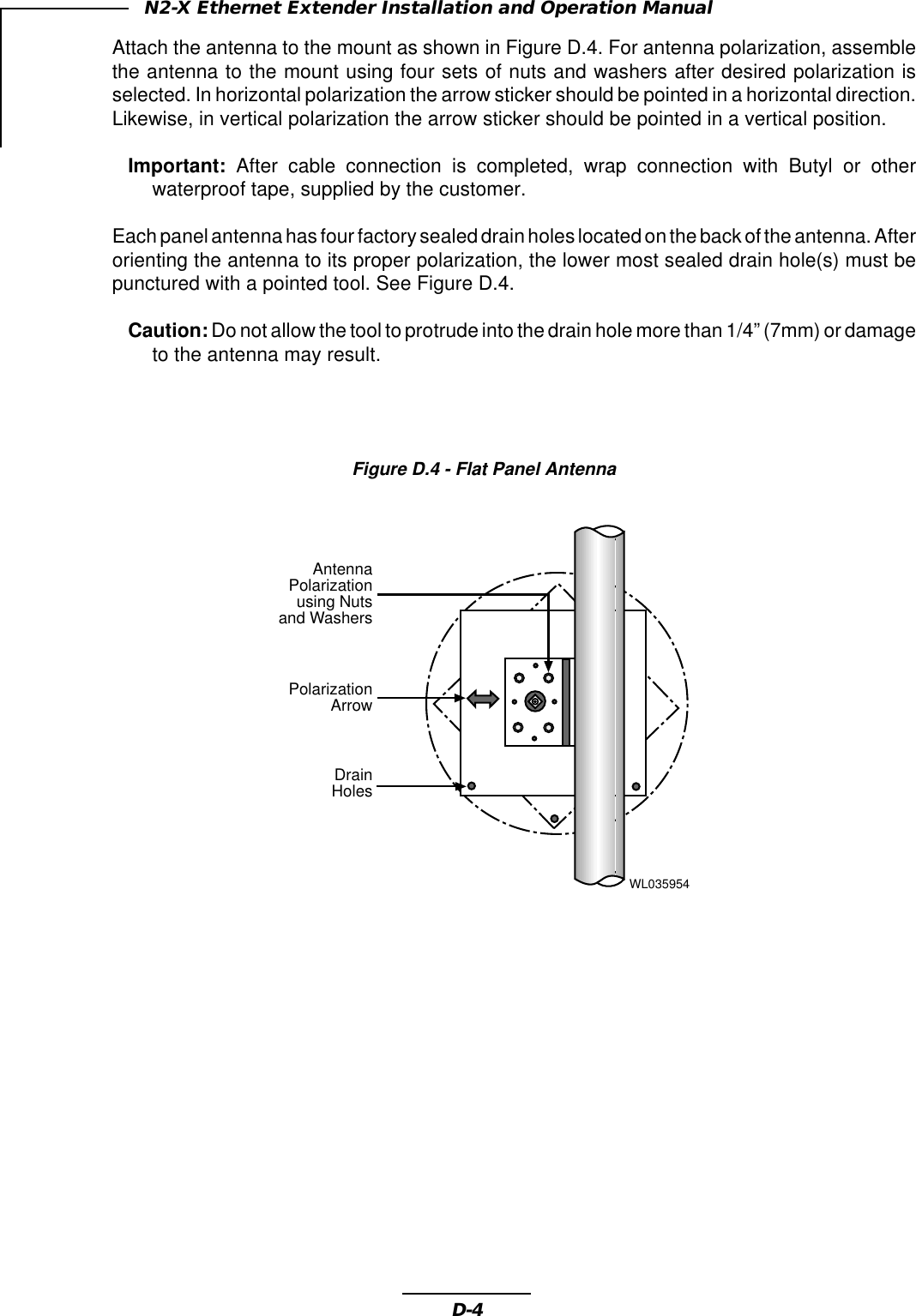
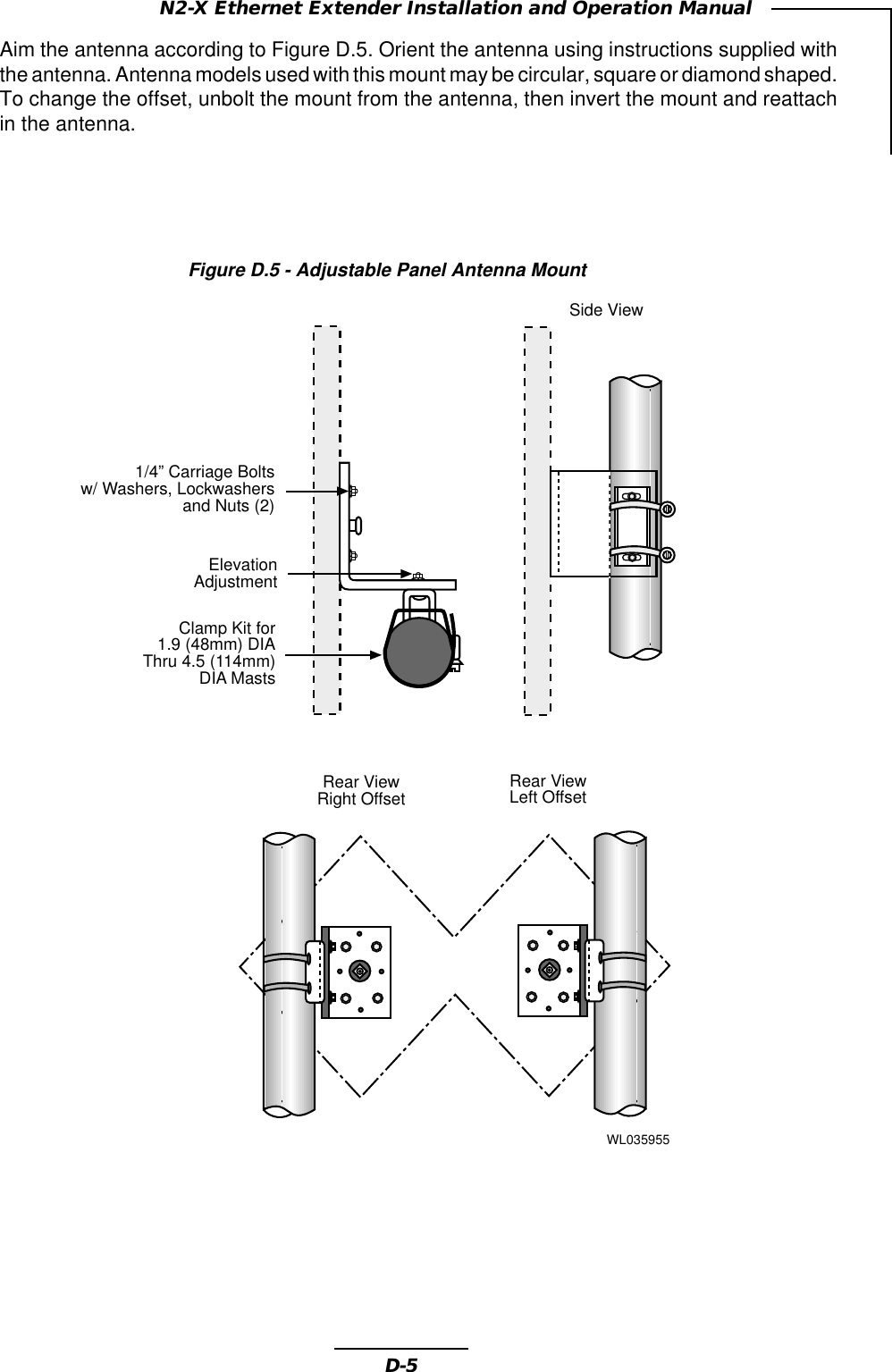
![viiiN2-X Ethernet Extender Installation and Operation ManualMicrowave Antenna Radiation WarningDesigned for point-to-point operation, an N2-X Ethernet Extender microwave radio system willuse directional antennas to transmit and receive microwave signals. These directional anten-nas are usually circular or rectangular in shape, are generally located outdoors, and are usuallymounted on a tower or mast.Referencing OET Bulletin 65 (Edition 97-01, August 1997) from the Federal CommunicationCommission’s Office of Engineering & Technology, limits for maximum permissible exposure(MPE) to microwave signals have been adopted by the FCC for both Occupational/Controlledenvironments and General Population/Uncontrolled environments. These limits are 5.0 mW/cm2 and 1.0 mW/cm2, respectively, with averaging times of six-minutes and thirty-minutes,respectively.The closer you are to the front center-point of a microwave antenna, the greater the powerdensity of its transmitted microwave signal. Unless you are very close, however, microwaveexposure levels will fall far below the MPE limits. To determine how close to a microwaveantenna you can be and still remain below the MPE limits noted above, “worst case” predictionsof the field strength and power density levels in the vicinity of an N2-X Ethernet Extender™microwave antenna can be made from the following calculations. The equation is generallyaccurate in the far-field of an antenna, and will over-predict power density in the near-field (i.e.close to the antenna).S = PG/4πR2where: S = power density (in mW/cm2)P = power input to the antenna (mW)G = power gain of the antenna in the direction of interest relative to an isotropicradiatorR = distance to the center of radiation of the antenna (cm)Note that G, the power gain factor, is usually expressed in logarithmic terms (i.e., dB), and mustbe converted using the following equation:G = 10 dB/10For example, a logarithmic power gain of 24 dB is equal to a numeric gain of 251.19.Assuming (1) maximum output power from the N2-X Ethernet Extender (+3.5 dBm [2.238 mW]),(2) no signal loss in the cable connecting the N2-X Ethernet Extender to the antenna, and (3)the use of a 27 dBi gain parabolic antenna, the 5.0 mW/cm2 and 1.0 mW/cm2 MPE power densitylimits would be reached at distances of approximately 4.22 cm and 9.44 cm, respectively.Wireless, Inc. fully supports the FCC’s adopted MPE limits, and recommends that personnelmaintain appropriate distances from the front of all directional microwave antennas. Should youhave questions about N2-X Ethernet Extender™ microwave signal radiation, please contact theWireless, Inc. Customer Service Department.](https://usermanual.wiki/Wireless/N2X5-3S1-16B.Dec-17-draft-pdf-version/User-Guide-80658-Page-8.png)