Xeline LTd SU-200BX PLC(PowerLine Communication) Modem User Manual SU 200BX Manual eng V08
Xeline Co., LTd. PLC(PowerLine Communication) Modem SU 200BX Manual eng V08
UserManual.wiki
>
Xeline LTd
>
SU 200BX User Manual
Users Manual
Navigation menu
Upload a User Manual
Namespaces
Wiki Guide
HTML
PDF
Info
Views
User Manual
Discussion / Help
Navigation

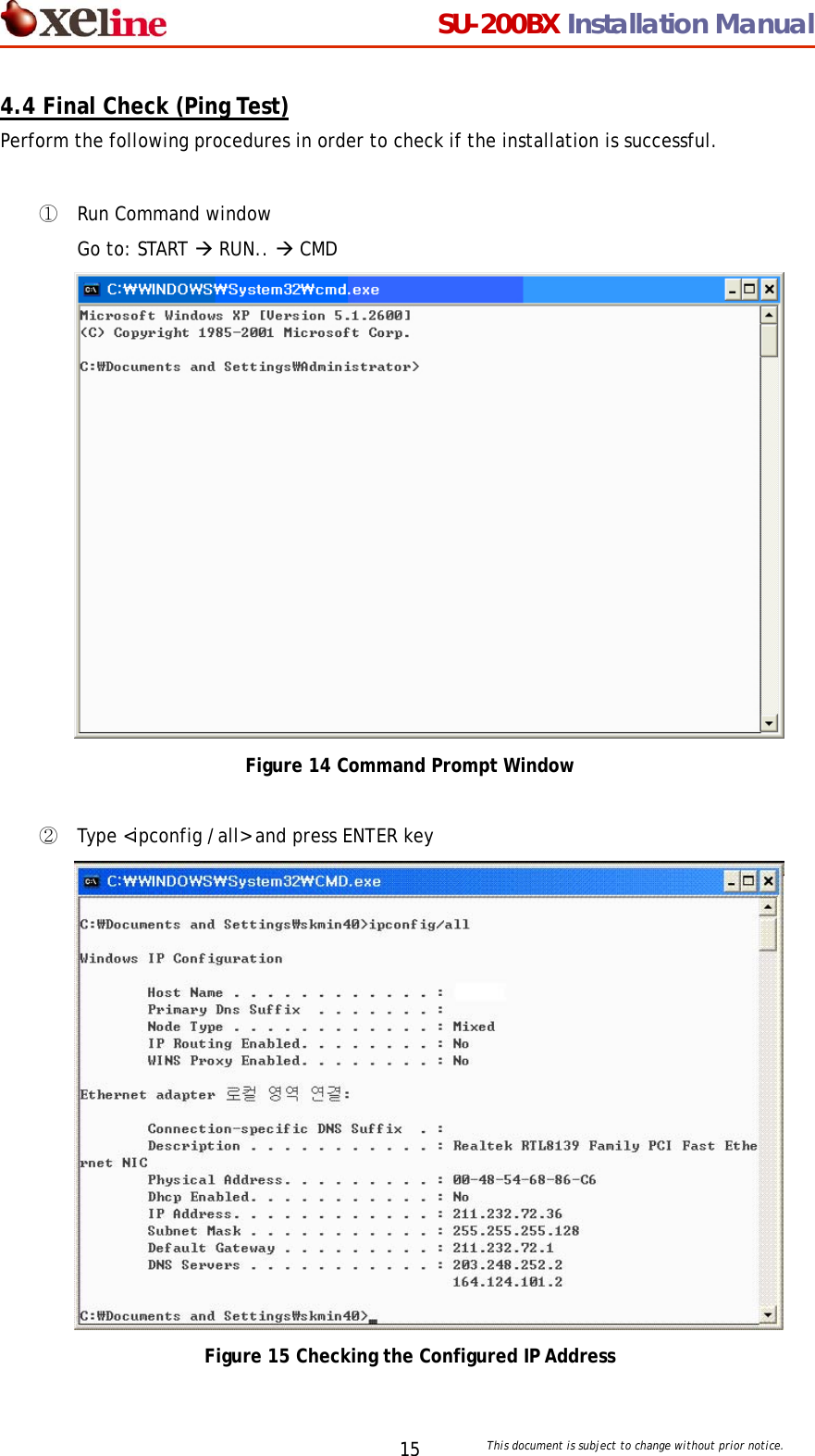
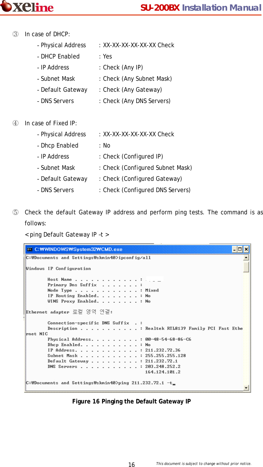
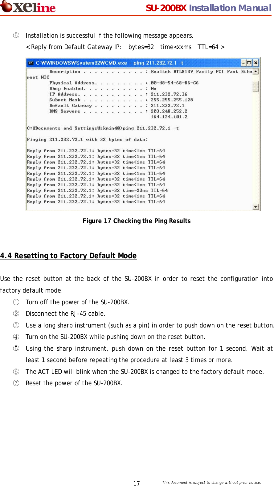
![SU-200BX Installation Manual This document is subject to change without prior notice. 13③ Select INTERNET PROTOCOL (TCP/IP) and click [Properties]. Figure 10 Internet Protocol (TCP/IP) ④ Enter the IP address and DNS server address provided by the Internet Service Provider (ISP). i. For DHCP IP Addresses: Select OBTAIN AN IP ADDRESS AUTOMATICALLY. Then select the OBTAIN THE FOLLOWING DNS SERVER ADDRESS option. Click [OK] to continue. ii. For Fixed IP Addresses: Enter the addresses as shown in the example below. Click [OK]. Figure 11 Fixed IP Address Setting Click Click Example IP address Example DNS address 211 168 11 249 255 255 255 128 211 168 11 129 147 46 80 1 147 46 80 2](https://usermanual.wiki/Xeline-LTd/SU-200BX/User-Guide-560215-Page-13.png)
![SU-200BX Installation Manual This document is subject to change without prior notice. 14⑤ Select the SHOW ICON IN TASKBAR WHEN CONNECTED option and click [OK]. Figure 12 Show Icon in TaskBar ⑥ Configuring your computer for Internet connection is now complete. You can check your connection status by clicking the network icon in the taskbar as shown below. Figure 13 Network Configuration Complete Click](https://usermanual.wiki/Xeline-LTd/SU-200BX/User-Guide-560215-Page-14.png)