Xingyaohua T7AH-2400 Radio User Manual
Shenzhen Xingyaohua Industrial Co., Ltd. Radio
UserManual.wiki
>
Xingyaohua
>
T7AH 2400 User Manual
User Manual
Navigation menu
Upload a User Manual
Namespaces
Wiki Guide
HTML
PDF
Info
Views
User Manual
Discussion / Help
Navigation

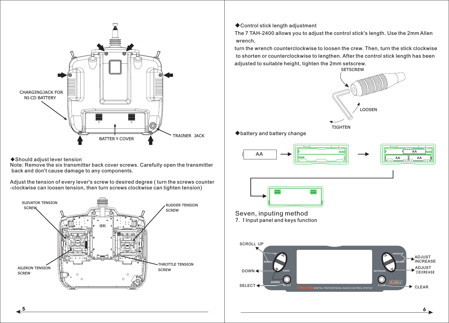
![78Input key and scroll under the condition of input, all will make a sound to confirm the correct.Add keys and Decrease keys have rapidly increasing or decreasing function(continuous pressure which will rapidly increasing or decreasing)Sometimes occur numerical unchanged, but have the confirmed sound, that is because of the numerical value in the decimal point,no suggested in the LCD screen, but the internal value have changed.Available whento select functionavailable when to select setted project{}up keydown key UPDNselect key SELENTERLISTAlert mode switchDNSEL(press with simultaneously)listCO NT+-SELChange screen light and shadeincrease keydecrease keyclear keyavailable when to set the information7.2 Inputing mode and function selectionBoot screenS as described below:SCROLL UP and SCROLL DOWN, the two keys used to flip menus. The SELECT is select key, used to select the menu, ADJUST INCREASE and ADJUST DECREAS are used to change the specific settled date under the options. CLEAR is reseted button, make the date to reset the default values.In additon, these keys has some combination setting functions:1 In the boot screen, pressing SCROLL DOWN and the SELECT keys simultaneously, you can enter the system setup menu interface, in this display interface, pressing the SCROLL UP and SELECT keys, you can enter the system setup menu list interface. At the same time in SCROLL DOWN and SELECT keys ,you can return to the system setup menu interface, once again, then you can return to the main display interface.2, After startup, pressing SCROLL DOWN and SELECT keys simultaneously, you can enter the function setup menu interface, pressing SCROLL UP and SELECT buttons, you can enter the function setting menu list. When in the interface, you can press SCROLL DOWN and SELECT keys simultaneously, exist to function setup menu interface, then press again, go back to the main display interface.DECREASE、CLEAR, The specific function of this several LCD operation buttonsThe text below the key panel figure state:Panel SCROLL UP、SCROLL DOWN、SELECT、ADJUST INCREASE、ADJUST Eight, aircraft quick setup guide◇choose aircraft typeTurn the power and press DOWN and SELECT keys simultaneously, the RC turns into the system setup mode.Press the UP or DOWN key until TYPE SELECT appears on the screen.According to the UP or DOWN until the SELECT button, by appear on the screen.Press INCREASE or DECREASE key, the black triangle towards or in "HELI" and ◆Servo ReversingPress to enter TYPE SELECT[TYPE SELECT]MODEL 1HELIINCREASE and DECREASE keyHold while turning on transmitterACROAccept new model type CHANNGE SCROLL UPDOWNSELECTADJUST INCREASEADJUST DECREASECLEARMODEL 0 HELI000112.5ms FRAME RATE10.3V Model number Launch control data update cycleCurrent control the plane type Throttle fine-tuning quantity displayRudder fine-tuning quantity display Aileron fine-tuning quantity display Elevator fine- tuning quantity displayUPSEL(press with simultaneously)SEL +-(press with simultaneously)with](https://usermanual.wiki/Xingyaohua/T7AH-2400/User-Guide-1601195-Page-5.png)
![910◇To Access Servo ReversingTurn the power on and press the DOWN and SELECT keys simultaneously to enter the function mode.Press the UP and DOWN keys until REVERSING SW appears on the screen.Press the SELECT key to select the desired channel, and then press the INCREASE or DECREASE key reverse or normal servo direction.◆Travel AsjustmentInsert English instruction 26 page below◇To Access Travel AdjustmentTurn on the power and press the DOWN and SELECT keys to enter into the function model press the UP or DOWN key until TRAVEL ADJUST appears on the screen. Press selected key to move cursor arrow to the desired channel.Note: if your aircraft flaps is controlled by two independent servos, please see page 44. The rear wing type for selected explicitly pointed out the programming flaperon.◆Only aircraft adjust for HELI, just have this feature setup.T7AH-2400 offers four independent pitch curves, each with up to five adjustable points. This function allocates a separate pitch curve setting during normal, stunt 1, stunt 2 and hold modes. Once the pitch curves are adjusted, each can beactivated in flight using the three-position flight mode and throttle hold switches. Each of the five points of the pitch curve are independently adjustable from 0–100%. These five points correspond to low, 25%, mid, 75% and high stick positions. See Page 94 for more details on setting up pitch curves.◇To Access the Pitch Curve FunctionTurn the power on and press the DowN and SELECT keys simultaneously to enter the function mode.Press the UP or DOWN key until PITCH CURVE NORM appears on the screen.Press the SELECT key to select the stick position that you wish to adjust the pitch.● L = Low● 1 = 25%● 2 = 50%● 3 = 75%● H = HighPress the INCREASE or DECREASE key to adjust the pitch position.Recommended Initial Pitch Settings● L= -4º● 2= 5º● H= 9ºNote: For more information about setting up pitch curves, see continue pages.◆Adjust the three sections of switch with corresponding normal model under the throttle curve Only aircraft adjust for HELI, just have this setup function.[REVERSING SW]GEARPress to select REV. or NORMPress to enter REVERSEPress to enterFunction ModePress to selectdesired channelNORM ch 1 2 3 4 5 6 7REV.[TRAVEL ADJUST]THRO H 100%L 100%ELEVD 100%U 100%AILE L 100%R 100%RUDDL 100%R 100%Selected channelPress to enterTRAVEL ADJUSTPress to enterFunction ModePress to returnvalue to defaultPress to selectdesired channelPress to adjust value[PITCH CURVE]Point-351 51INH1 2 3HLINPress to enterPITCH CURVEPress to enterFunction ModePress to selectdesired pointsPress to change OUTNORM"ACRO" appear alternately, if not show "the YES-> CLEAR KEY, it means the current plane is the type, if not be, it means you can choose the aircraft type by pressing CLEAR key.](https://usermanual.wiki/Xingyaohua/T7AH-2400/User-Guide-1601195-Page-6.png)
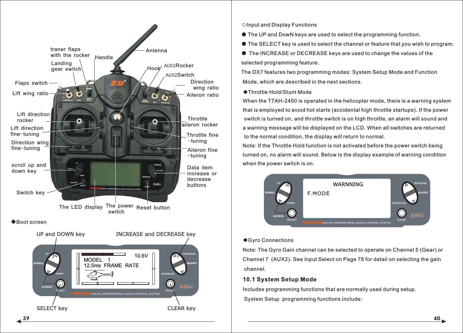
![11Adjustment of the throttle curves is similar to the pitch curve adjustment described on the preceding page. Three throttle curves are available: normal, st1 and st2. All throttle curves have five adjustable points—low, 25%, 50%, 75% and high. Flight modes are located on the 3-position flight mode switch. The throttle curve is in the normal mode when the Flight Mode switch is in the rear position and the Throttle Hold switch is rearward◇To Access the Throttle Curve FunctionTurn the power on and press the DOWN and SELECT keys simultaneously to enter the function mode.Press the UP or DOWN key until THROTTLE CURVE NORM appears on screen.Press the SELECT key to select the stick position that you wish to adjust the throttle.● L= Low● 1= 25%● 2= 50%● 3= 75%● H= HighPress the INCREASE or DECREASE key to adjust the throttle value of the selected throttle position.For more information about setting up Throttle Curves see continue pages. For additional features like Dual Rates and Mixing etc, see the appropriate pages listed in the table of contents. The more detail information about the HEI mode, please see the HEL part of this book.NINE, Aircraft Programming guideControl Identification and Location - Airplane Mode 1-ACROThrottle ALTThe Throttle ALT function makes the throttle stick trim active only when the throttle stick is at less than half throttle. This allows accurate adjustments without affecting the mid to high throttle position.◆General InformationPress to adjust values[THRO CURVE]NORMPoint-L51 510.0%1 2 3 HLIN OUT Press to enterTHROTTLE CURVEPress to enterFunction ModePress to selectdesired points12MODEL 112.5ms FRAME RATE10.6VINCREASE and DECREASE keyUP and DOWN keySELECT key CLEAR keyLanding gear switchFlaps switchLift wing ratioLift direction rockerLift directionfine-tuningDirection wing fine-tuningscroll up and down keySwitch keyThe LED display Reset buttonData item increase ordecreasebuttonsAileron fine-tuning Throttle aileron rockerThrottle fine -tuningAileron ratioAUX2SwitchDirection wing ratioHookThe power switchtraner flaps with the rocker HandleAntennaAUX2Rocker](https://usermanual.wiki/Xingyaohua/T7AH-2400/User-Guide-1601195-Page-7.png)
![13 14◇ Key Input and Display FunctionsThe UP and DOWN keys are used to select the programming function.The SELECT key is used to select the channel or feature that you wish to program.The INCREASE and DECREASE keys are used to change the values of the selected programming feature.T7AH-2400 features two programming modes: System Mode and Function Mode.9.1System Mode FunctionsSystem Mode◇ To Enter the System List ModePress and hold the DOWN and SELECT keys simultaneously before turning the power, then turn the transmitter power switch on to enter the System Mode.While in the System Mode, press the UP and SELECT keys simultaneously to access the “List” mode.Use the UP and DOWN keys to scroll through the available function.Press DOWN and SELECT to enter a selected function.In this mode, servos are activated.By pressing the DOWN and SELECT keys twice simultaneously, you can return to the main screen.◇To Enter the System Setup Mode● With the power switch off, press and hold the DOWN and SELECT keys simultaneously.● Turn on the power switch.● The system will display the last screen that was used in system set up mode. You are now in System Mode.◇ To Exit the System Setup Mode● Press the DowN and SELECT keys simultaneously. The main screen will be displayed.[MODEL SELECT ]SELECTMODEL 1ACRO DSM Hold while turning on transmitter to enter System Mode[MODEL NAME]MODEL 1 ACRO< >[MODEL SELECT]SELECTMODEL 1ACRO [ TYPE SELECT ]MODEL 1HELIACRO[THRO RECOVERY]INH [MODEL RESET]MODEL 1 ACRO DATA RESETINTEG-T03:23:13[D/R SWITCH SEL]INVALID[WING TYPE] FLAPERON OFFDELTA OFFV-TAIL OFF[TRAINER]INH[INPUT SELECT]AUX2:2P SWAUX2 TRIM:INHFLAP:SYSTEMFLAP TRIM:INHGEAR:2P SWModel Select (Page 15)Model Name (Page 16)Type Select (Page 16)Model Reset (Page 17)Trainer (Page 18)Dual Rate Select (Page 25)Wing Type (Page 20)Input Select (Page 19)Throttle Recovery(Page 46)[SYSTEM LIST]TRAINERINPUT SEL.WING TYPEMODEL SELMODEL NAMETYPE SEL.MODEL RES.UP and DOWN keyHold while turning on transmitterD/R SWTH RECOV.STICKMODCHNL RASS[SKMODE SELECT]ELEVRUDDTHROAILEMODE 1[CHNO ASSGIN]1:TH RO2:AILE3:EL EV4:RU DD5:GE AR6:FLAP7:AU X2(Page 19)Stick mode select(Page 19)Channel no assign9.2 System Mode FlowchartSystem Mode includes programming functions that are normally used during set up. System programming functions include:](https://usermanual.wiki/Xingyaohua/T7AH-2400/User-Guide-1601195-Page-8.png)
![15 16◇To Enter the Model Select FunctionPress the DOWN and SELECT keys simultaneously and turn the power switch on to access the System Setup Mode.Press the INCREASE or DECREASE key until the MODEL SELECT appears on the screen .Press the INCREASE or DECREASE key to select the desired model memory.◇ To Enter the Model Cope FunctionPress the DOWN and SELECT keys simultaneously and turn the power switch on to access the System Setup Mode.Press the INCREASE or DECREASE key until the MODEL SELECT appears on thescreen .Press the SELECT key to enter COPY SCREEN.Press the INCREASE or DECREASE key to select the desired copy memory.Press the CLEAR key to copy mode to the desired model memory.Note: The model you copy to will have its memory replaced with the new model's memory, and the programming information for the model to be copied will be erased.◆Model NameThe Model Name function is used to input and assign the model's name to a specific memory, allowing identification of each model's program. Each model's name is displayed on the main screen when that model is selected. Up to eight letters and numbers and are available.◇To Enter the Model Name FunctionPress the DOWN and SELECT keys simultaneously, then turn on the transmitter.Press the UP or DOWN key until the MODEL NAME appears on the screen.Press the SELECT key to move the cursor to the desired character's position.Press the INCREASE or DECREASE key to select the desired character. ◇Type Select FunctionThe T7AH-2400 features two programming types: Airplane and Helicopter. The DX7 can memorize data for up to six fixed wing aircraft and six helicopters model and the model type will automatically be stored with each model memory.Hold while turning on transmitter[MODEL SELECT ]SELECTMODEL 1ACRO Hold while turning on transmitterINCREASE and DECREASE keyUP and DOWN key[MODEL SELECT]MODEL 1HELI MODEL 2ACRO COPYINCREASE and DECREASE keyPress to selectMODEL SELECTPress to enterfunction main screenPress to enterCOPY screenPress to copyselected model[MODEL NAME]MODEL 1 ACRODSM <EXTRA 300>Press to enter MODEL NAMEHold while turning on transmitterINCREASE and DECREASE key[TYPE SELECT]MODEL 1HELIINCREASE and DECREASE keyPress to enterTYPE SELECTACRO](https://usermanual.wiki/Xingyaohua/T7AH-2400/User-Guide-1601195-Page-9.png)
![17 18◇To Enter the Type Select ModePress the DOWN and SELECT keys simultaneously, then turn on the transmitter.Press the UP key until the TYPE SELECT appears on the screen.◇To Select a Model TypePress the INCREASE or DECREASE key to witch between the heli or acro model type.press the CLEAR key to accept the new model type . All settings will be set to the factory defaults if the selected memory group is previously used type label ◆Model Reset and Integrated Timer ResetThe Model Reset function allows the model memory of the current model to bereset to the factory default setting. This screen also allows the integrated timer to be reset.◇To Perform a DATA RESET or Reset the Integrated TimerPress the DOWN and SELECT keys simultaneously, then turn on the transmitter..◆Enhanced wireless TrainerThe T7AH-2400 offers a Wireless Trainer Function. Premise is the transmitter's and transmitter's sets are the sameTo Enter the Trainer Mode:Press the DOWN and SELECT keys simultaneously, then turn on the transmitter.Press the UP key until TRAINER function appears on screen.Press the INCREASE or DECREASE key to activate or close Trainer function, then TRAINER TRIM only used as a traniner switches.◆Throttle RecoveryThe T7AH-2400 has a unique throttle trim recovery feature. Throttle Recovery stores the last known throttle trim position once throttle restore function is activated. That stored position is then recalled by moving the throttle trim up (open) one notch when the throttle trim is moved to the full down (closed) position. This makes shutting off the engine and restarting it with the correct trim position easy.To Activate the Throttle Recovery FunctionPress the DOWN and SELECT keys simultaneously, then turn on the transmitter.Press the UP key until THRO RECOVERY appears on screen.Press the INCREASE or DECREASE key to turn on/off the Throttle Recovery function.[TYPE SELECT]MODEL 1HELIINCREASE and DECREASE keyHold while turning on transmitterACROAccept new model typeYES CLEAR KEY[MODEL RESET]MODEL 1 ACRO DATA RESETINTEG-TPress to enter MODEL RESETHold while turningon transmitterPress to selectRESET or INTEG-TPress to resetdata or timer0:00:34INCREASE and DECREASE keyPress to select MODEL SELECTPress to enterfunction main screenPress to enterCOPY screenPress to copyselected modelINH [TRAINER ]Press the UP or DOWN key until MODEL RESET appears on the screen.Use the SELECT key to select DATA RESET or INTE-T.When DATA RESET is selected, pressing the CLEAR key will reset the date to the factory default setting for that model, or if INTE-T is selected, the integrated timer will be reset to 0:00:00◆Pole modeThe T7AH-2400 have in four different control rod "mode" (0, 1, 2, 3). Different mode corresponding to operation function of different control rod. Usually, set in "mode" 1.](https://usermanual.wiki/Xingyaohua/T7AH-2400/User-Guide-1601195-Page-10.png)
![19 20(The ROKER(HOVER THROTTLE) provides proportional trim function, while the AUX2 channel allows the switch of 2 or 3 positions. Or you can inhibit the AUX2 rocker as well to prevent inadvertent changes. You can also choose the rocker as an AUX2 channel proportional outputing. )In addition, you have 3 choices to activate/inhibit FLAP SYSTEM:● System (3-position switch)● Rocker● INH(The ROKER(HOVER THROTTLE) provides proportional trim function, while the AUX2 channel allows the switch of 2 or 3 positions. Or you can inhibit the AUX2 rocker as well to prevent inadvertent changes. You can also choose the rocker as an AUX2 channel proportional outputing. )◆Wing TypeIn the fixed wing mode, the 7AH-2400 offers three different wing types to choosefrom: Normal, Flaperon and Delta. In addition, V-Tail mixing is available from the Wing Type screen.◆NormalWhen the Flaperon and Delta wing function are off, Normal wing type is selected. Use this wing type with common aircraft that utilize only one servo for both ailerons. Normal is the default setting.◆Flaperon Wing Type SelectionFlaperons require the use of one servo for each aileron and allow the use of ailerons as flaps or spoilers. This function also allows the precise independent adjust of up and down travel, and independent sub-trim and differential of each aileron.◇To Access Input SelectPress the DOWN and SELECT keys simultaneously, then turn on the transmitter.Press the UP key until the INPUT SELECT function appears on screen.Here you have 4 choices that can be used to operate auxiliary channel :● 2-position switch● 3-position switch● Rocker● INH◆Delta Wing Type SelectionDelta wing arrangements combine the function of ailerons with the function of the elevator to allow precise control of both roll and pitch.[SKMODE SELECT]MODE 1ELEVRUDDTHROAILE◆Input SelectThe purpose of the Input Selection Function is to assign the activation device for the AUX2 channel and the FlAP Channel.Change Pole mode From Main Screen Display press the DOWN and SELECT keys simultaneously to enter thFunction Mode. Press the DOWN and SELECT keys simultaneously, the turn the transmitter on. Press the UP key until SKMODE SELECT appear on green. Press the INCREASE and DECREASE keys to change the pole mode.。◆Channels Distribute The T7AH-2400 can assign 7 channels to output in any channel, you can choose a different style of the channel allocation, can also customize the output channel allocation output.[CHNO ASSGIN]1:THRO2:AILE3:ELEV4:RUDD5:GEAR6:FLAP7:AUX2[INPUT SELECT]AUX2 TRIM:INHFLAP: SYSTEMPress to enter INPUT SELECTHold while turning on the transmitterFLAP TRIM:INHINCREASE and DECREASE keyAUX2: 2P SWGEAR:2P SWChange the channel distrubutePress the SELECT and DOWN keys simultaneously and turn the transmitter on.Press the UP key until CHNO ASSGIN appears on screen.Press the SELECT key to select channel that you wish to output signal.Press the INCREASE or DECREASE key to change the signal out putted by channel. Press the CLEAR key restoring default values.](https://usermanual.wiki/Xingyaohua/T7AH-2400/User-Guide-1601195-Page-11.png)
![21 22◇To Enter the Tail Wing Type FunctionPress the DOWN and SELECT keys simultaneously, then turn on the transmitter.Press the UP key until WING TYPE function appears on screen. ◇To Select a Wing TypePress the INCREASE or DECREASE key until the desired wing type is highlighted on screen: NORMAL, FLAPERON, DELTA WING.Note: When Flaperon or Delta Wing type is selected, the travel adjustment is used to adjust the individual servo throw, while the combined aileron travel is adjusted with the aileron dual rate. It's also possible to set aileron differential. Reverse switches are applicable for each servo. Neutral adjustments of each servo need thought the Sub Trim Function to complete.V-Tail Type Servo ConnectionsELEV Servo Port(Left V-Tail)RUDD Servo Port(Right V-Tail)Triangle type steering gear connection.● AILE servo port (right aileron)● AUX1 servo port (left aileron)◆ V tail type steering gear connection◆ RUDD servo right aileron)● AILE servo port (left aileron)Flaperon Wing Type Servo Connections• AILE ser• AUX1 servo port (left aileron)vo port (right aileron)AUX1 Servo Port(Left Aileron)AILE Servo Port (Right Aileron)Flaperon WING Type ConnectionAILE Servo Port(Left Aileron)ELEV Servo Port (Right Aileron)Delta Wing Type ConnectionV-Tail Type ConnectionRUDD servo port(right V-tail)ELEV servo port (leftV-tail)• • Delta Wing Type Servo ConnectionsELEV servo port (right aileron)AILE servo port (left aileron)• • Flaperon Active:[WING TYPE]FLAPERON ONV-TAIL OFFV-Tail Active:[WING TYPE]FLAPERON OFFV-TAIL ON Delta Active:[WING TYPE]DELTA ON[WING TYPE]FLAPERON DELTA V-TAIL Hold while turning on the transmitterINCREASE and DECREASE keyOFF OFF OFF WING TYPE FUNCTION Press to enter ◆Flaperon Wing Type Servo Connections● AILE servo port (right aileron)● AUX1 servo port (left aileron)](https://usermanual.wiki/Xingyaohua/T7AH-2400/User-Guide-1601195-Page-12.png)
![23 24◆Function Mode◇To Enter Function Mode● From Main Screen Display press the DowN and SELECT keys simultaneously to enter the Function Mode.● Use the UP or DowN keys to select the desired function.● Use the SELECT key to scroll to the desired channel.● Use the INCREASE and DECREASE keys to change the values or positions of the selected channel.● Use the CLEAR key is used to return the selected value to the factory default settings.9.3Function Mode FlowchartInformation pertaining to each function is explained on the following pages. Functions will appear on the screen in the same order they are shown on the flow chart below:[D/R & EXP]POS-0AILED/R 100%EXP LINOUTPUTDual Rate & Exponential (Page 26)Servo Monitor THROAILEELEVRUDDGEARFLAPAUX2 (Page 38)Reverse Switch[ REVERSING SW ]NORMGEARch 1 2 3 4 5 6 7REV. (Page 27)[PROG.MIX1]THRO≥ THRO ONRATE: 0%0%SW:ONOFFSET: 0Programmable Mixing (1-6) (Page 34)[DIFFERENTIAL]FLAPERONNORM 0%Differential (Page 32)[FLAP SYS.] NORMFLAP ELEVNORM UP100% 000MIDLANDAUTO INHDN100%0%Flap System (Page 30)Sub Trim (Page 28)[SUB TRIM] THRO AILE0 00 0ELEV RUDD[TRAVEL ADJUST]THRO H 100%L 100%ELEVD 100%U 100%AILE L 100%R 100%RUDDL 100%R 100%Travel Adjust (Page 29)[AILE->RUDD MIX]RATE: 0%OFFSW: MIXAileron-to-RudderMix (Page 30)Elevator-to-Flap (Page 30)[ELEV->FLAP MIX]RATE: D 0%ONU 0%SW:FLAP0◆Function List ModesThe list mode screens display all the functions on screen allowing the access of any function without having to scroll through each screen.Note that there are two list modes: a System Setup List Mode and a Function List Mode To enter the Function List Mode, with the system on and in any function mode screen, press the UP and SELECT keys simultaneously.In list mode, pressing the UP and DOWN keys will move the cursor to the desired function. Then pressing the DOWN and SELECT keys simultaneously will access the selected function.MODEL 112.5ms FRAME RATE10.6VINCREASE and DECREASE keyUP and DOWN keySELECT key CLEAR key[FUNCTION LIST]DUAL RATEEL≥FL MIXTRAV ADJ.SUB TRIMREV. SWEXPONENT.PROG.MIX3PROG.MIX2PROG.MIX1FLAP SYS.AI≥RU MIXUP and DOWN keyPress to enter function List ModeINCREASE and DECREASE key[ TIMER ]MODEL 1DOWN-T00:00Timer (Page 36)SW:ADJUST](https://usermanual.wiki/Xingyaohua/T7AH-2400/User-Guide-1601195-Page-13.png)
![25 26◇To Enter the Function List Mode● Turn the transmitter on.● From the main screen, press the UP and SELECT keys simultaneously.● The system is in Function List Mode now and will display a list of all the available functions .● Use the UP and DOWN keys to Scroll through the available function.● Press DOWN and SELECT to enter a selected function.◇To Exit the Function List Mode● Press the DOWN and SELECT keys simultaneously twice. The system will return to the main screen.◆Dual Rate and Switch SelectThe D/R switch select function allows the dual and expo rates to be selected via individual switches (aileron, elevator and rudder D/R switches) or to be conveniently combined on a single switch. When combined to a single switch the following switch options are available:● COM AILE: Aileron D/R switch● COM ELEV: Elevator D/R switch● COM RUDD: Rudder D/R switch● FLAP 2: Flap switch in the lower position● FLAP 0: Flap switch in the upper position● INDIVID: D/R activated by it’s individual aileron, elevator and rudder switches.◇To Activate Dual Rate and Switch SelectPress and hold the DOWN and SELECT keys simultaneously to enter system mode.Press the UP or DowN key until D/R SWITCH SEL appears on the screen.Press the INCREASE or DECREASE keys to select the desired switch(es) you wish to operate the D/R and Expo function. and selectedwith a switch. Dual rates and expos are available on the aileron, elevator and rudder channels. Changing the dual rate value not only affects the maximum control authourity but also affects the overall sensitivity of control. A higher rate yields a higher overall sensitivity. The sensitivity around center can be tailored using the Exponential function to precisely adjust.Dual and Expo rates can be controlled by their respective dual rate switches or by one common switch. The choices for this are found on the D/R SWITCH SEL screen in the System Setup Mode for Airplanes.Dual rate values are adjustable from 0–125%. The factory default settings for both the 0 and 1 switch positions are 100%. Exponential values are adjustable from -100% to +100%. Either switch position may be selected as the low or high rate by placing the switch in the desired position and adjusting the value accordingly.◇To Adjust the Dual and Expo RatesPress the DOWN and SELECT keys simultaneously to access the Function Mode.In Function Mode, use the UP or DOWN keys to select the D/R or EXP screen.Press the INCREASE or DECREASE key to select the desired channel.Press the SELECT key to highlight the D/R or EXPO function.Adjust the dual rate values for the selected switch position using the INCREASE or DECREASE key.[D/R & EXP]POS-0AILED/R 100%EXP LINOUTPUTPress to adjust valuePress to enterDUAL RATEPress to enterFunction ModePress to selectdesired channelPress to return valueto default setting[ D/R SWITCH SEL ]UP and DOWN keyPress to enter function List ModeINCREASE and DECREASE keyINDIVID◆Dual Rate and ExponentialThe Dual Rate and Exponential function allows two control rates to be programmedhe Dual Rate and Expo functions for aileron, elevator and rudder can be combined on a single switch, high or low rates to be selected via one switch. The choices for this are found on the D/R SWITCH SEL screen in the System Setup Mode for Airplanes.(have a look at page 50.)The Exponential function allows two exponential rates to be programmed and selected with a switch. Exponential is available on the aileron, elevator and rudder channels. Changing the exponential value does not affect the maximum control authority but only affects control sensitivity. Exponential is normally used to reduce control sensitivity around neutral while still allowing high control authority at the](https://usermanual.wiki/Xingyaohua/T7AH-2400/User-Guide-1601195-Page-14.png)
![27 28◇To Adjust the ExponentialPress the DOWN and SELECT keys simultaneously to access the Function Mode.In Function Mode, use the UP or DOWN keys to select the DUAL RATE and EXPONENTIAL screen.Press the INCREASE or DECREASE key to select the desired channel (AILE, ELEV or RUDD).Move the selected channel’s dual rate switch to the desired position, 0 or 1.Press the SELECT key until EXP is highlighted on the screen.Using the INCREASE or DECREASE key to adjust the Expo rate values.◆Reverse SwitchThe Reverse Switch function allows electronic means of reversing the servo’s throw. Servo reversing is available for all seven channels.◇To Access the Reverse Switch ModePress the DOWN and SELECT keys simultaneously to access the Function Mode.In Function Mode, use the UP or DOWN key to select the REVERSING SW screen.Press the SELECT key to access the desired channel.Press the INCREASE or DECREASE keys to reverse the servo direction The available channels are:● THRO: Throttle ● AILE: Aileron ● ELEV: Elevator ● RUDD: Rudder● GEAR: Retractable Landing Gear ● FLAP: Flap ● AUX2: Auxiliary 2◇To Access the Sub-Trim FunctionPress the DOWN and SELECT keys simultaneously to access the Function Mode.In Function Mode, use the UP or DowN key to select the SUB TRIM screen.Press the SELECT key to access the desired channel.Press the INCREASE or DECREASE keys to adjust the sub-trim position for that selected channel.[D/R & EXP]POS-0AILED/R 100%EXP LINOUTPUTPress to adjust valuePress to enterDUAL RATE and EXPONENTIALPress to enterFunction ModePress to selectdesired channelPress to return valueto default setting[REVERSING SW]NORMGEAR ch 1 2 3 4 5 6 7REV.Press to select REV. or NORMPress to enter REVERSEPress to enterFunction ModePress to selectdesired channel[SUB TRIM]THRO AILE 0ELEV Press to enter SUB TRIMPress to enterFunction ModePress to selectdesired channel Press to adjust sub-trim position00RUDD 0extremes of throw. The sensitivity around center can be tailored using theExponential function to precisely adjust control feel.Exponential rates can be controlled by their respective rate switches (aileron, elevator and rudder), or combined on a single switch.The choices for this are foundon the D/R SWITCH SEL screen in the System Setup Mode for Airplanes.Exponential is available for the aileron, elevator and rudder channels. Expo values are adjustable from-100% (full negative expo), straight line, and +100% (full positive expo). The factory default settings for both the 0 and 1 switch positions are straight line or 0%. You can select one between the witch's two position to open the desirable EXPO rate. The position of the switch is the place of ajusting the accordingly EXPONote: A negative Expo value will increase sensitivity around neutral, and a positive Expo value will decrease sensitivity around neutral. Normally a positive value is used to insensitize control response around neutra value.◆Sub-TrimThe Sub-Trim function allows you to electronically adjust the centering of each servo. Sub trim is individually adjustable for all seven channels, with a range of + or - 125% (+ or - 30 degrees servo travel).Caution: Do not use excessive sub-trim values as it is possible to overdrive the servo’s maximum travel.The available channels are:● THRO: Throttle ● AILE: Aileron ● ELEV: Elevator ● RUDD: Rudder● GEAR: Retractable Landing Gear ● FLAP: Flap ● AUX2: Auxiliary 2](https://usermanual.wiki/Xingyaohua/T7AH-2400/User-Guide-1601195-Page-15.png)
![29 30◆Travel AdjustThe Travel Adjust function allows the precise end-point adjustments of all seven channels in each direction independently. The travel adjust range is from 0–150%.Channel available for programming are:● THRO: Throttle ● AILE: Aileron ● ELEV: Elevator ● RUDD: Rudder● GEAR: Retractable Landing Gear ● FLAP: Flap ● AUX2: Auxiliary 2 ◇To Access the Travel Adjust FunctionPress the DOWN and SELECT keys simultaneously to access the Function Mode.In Function Mode, use the UP or DOWN key to select the TRAVEL ADJUST screen.Press the SELECT key to access the desired channel.Move the selected channel’s stick or switch in the desired direction that you wish to adjust.Press the INCREASE or DECREASE keys to adjust the end-point position for that selected channel's direction.◇To Access the Elevator-to-Flap MixingIn the Function Mode, use the UP or DOWN key to select the ELEVATOR TO FLAP MIXING function and press the UP and DowN keys simultaneously to access.Note: The flap mix switch, or the Mix switch, no matter which is selected, must be in the“ON” position to adjust values.To adjust the rate value, with the switch on, move the elevator stick in the desired position and press the INCREASE or DECREASE key to adjust the desired mix value.◇To Select the Switch to Operate the Flap MixPress the SELECT key to highlight SW.Press the INCREASE or DECREASE key to select the MIX or FLAP0 switch. [TRAVEL ADJUST]THRO H 100%L 100%ELEVD 100%U 100%AILE L 100%R 100%RUDDL 100%Selected channelPress to enterTRAVEL ADJUSTPress to enterFunction ModePress to returnvalue to defaultPress to selectdesired channelR 100%Press to adjust value Press to enter TRAVEL ADJUST[ ELEV - FLAP MIX ]Press to enterFunction Mode Press to select desired channelPress to adjust valueRATE: D 0%SW: FLAPOU 0%ON[ AILE- RUDD MIX ]Press to enter TRAVEL ADJUSTPress to enter Function Mode Press to select desired channelPress to adjust valueRATE: 0%SW: MIXOFF◆Elevator-to-Flap Mix FunctionWhen the Elevator-to-Flap Mixing System is active, and a value of flaps is inputted, the flaps will be deflected each time the elevator stick is used. The actual flap movement is independently adjustable for both up and down elevator. When used in this manner, the aircraft pitches much more quickly than normal. The uppermost position of the Flap Mixing Switch or the Mix Switch can be used to activate theElevator-to-Flap Mixing function. When you want to reverse the mixing directions, press the - key to change the mixing value from + to - (or - to +).◆Aileron-to-Rudder MixingIf the Aileron-to-Rudder Mixing function is designed, the rudder servo will move when the aileron stick is used, eliminating the need to coordinate these controls manually. This mixing program can be turned ON/OFF by a switch. The switches that can be selected are shown below, with their abbreviations as they appear on the screen and the corresponding switch positions. Mix values are adjustable from 0 to 125%. When adjusting the mix value, if an opposite mixing direction of the rudder servo is required, simply press the INCREASE or DECREASE key to change the mixing value from + to - or - to +. This will reverse the mixing direction of the rudder from its original direction.● ON: Mixing Always ON ● MIX Switch ON/OFF Using Mixing Switch● Flap 0 Switch ON/OFF Using Flap Mix Position 0● Flap 2 Switch ON/OFF Using Flap Mix Position 2](https://usermanual.wiki/Xingyaohua/T7AH-2400/User-Guide-1601195-Page-16.png)
![31 32◇To Access the Aileron-to-Rudder Mix FunctionPress the DOWN and SELECT keys simultaneously to access the Function Mode.In Function Mode, use the UP or DOWN key to select the AILE-RUDD MIX screen.Press the SELECT key to select RATE or SW (switch).◇To Adjust the Mix ValueWith RATE highlighted, press the INCREASE or DECREASE keys to adjust the mix value. Note: reversing mix directions is accessible.◇To Assign a SwitchWith SW be choosed, press the INCREASE or DECREASE keys to select the desired switch used to turn on/off the mix (Flap 0 or Mix).◆Flap SystemThe purpose of the Flap System is to set the flap and elevator positions for landing and takeoff. This is accomplished by selecting values for the elevator and flaps to be activated when the Land Switch is engaged. Three flap and elevator positions are available. The landing system can also be activated by a preset position of the throttle stick. Refer to the Automatic Landing Attitude section for more information on how to select the preset throttle position.Note: The Flap System is only be accessed when SYSTEM is selected under Flap in the Input Select screen. See page 46 for more detail◇Accessing and Utilizing the Flap SystemPress the UP and SELECT keys simultaneously to enter the Function Mode.Press the UP or DOWN keys until FLAP SYS appears in the upper left portion of the LCD. Press the SELECT key to move the cursor at the desired function (i.e., ELEV, FLAP , SPOI, AUTO). Note: The flap system can only be accessed when SYSTEM is selected in the Input Select screen under flaps. See page 41 for more details.Press the UP or DOWN keys to set the flap and elevator travel. The UP key adds up flap/elevator and the DOWN key adds down flap/elevator. The input is adjustable from 125% for flap and -200% for elevator.◆Automatic LandingWhen the Automatic Landing Function is active, the throttle stick will activate the landing system you have just set up. Any point of throttle stick travel can be set as the “auto-land” point. Once the throttle stick passes through this point and the LAND switch is in the MID, or land position, the landing system will be activated. Thus, the elevator and flaps would be activated. If the flap mixing switch is not in the LAND position, the throttle stick operation would have no effect on the landing system.◇To Activate the Automatic Landing FeatureIn the FLAP SYS. screen, press the SELECT key until AUTO is selected.Press the INCREASE or DECREASE key to activate the AUTOMATIC LANDING SYSTEM. Press the INCREASE or DECREASE key to adjust the value (0% = low stick while 100% = full stick). To clear the auto land point, press CLEAR key and the display will return to INH.◆Differential Aileron MixingNote: Only available when Flaperon or Elevon is selected, the Differential System is available (see Tail Wing Type Page 44).The Differential Aileron function allows precise electronic adjustments of the up vs. down aileron travel of both ailerons. Aileron differential is used to reduce unwanted yaw characteristics during roll inputs. In order to access the Differential Function, flaperon or elevon wing mixing must be selected and two servos must be used to operate the ailerons.[FLAP SYS.] NORMFLAP ELEVNORM UP100% 000MIDLANDAUTO INHDN100%0%Press to enter FLAP SYSTEMPress to enterFunction ModePress to returnvalue to defaultPress to highlightthe desired functionPress to adjust value[ DIFFERENTIAL ]Press to enter DIFFERENIALPress to enterFunction Mode Press to return value to defaultPress to adjust valueFLAPERONNORM 0%[FLAP SYS.] NORMFLAP ELEVNORM Up100% 00MIDLANDAUTO INHDN100%0%Press to enter FLAP SYSTEMPress to enterFunction Mode Press to return value to defaultPress to adjust value 0](https://usermanual.wiki/Xingyaohua/T7AH-2400/User-Guide-1601195-Page-17.png)
![33 34◇To Access the Differential Aileron Mixing FunctionPress the DOWN and SELECT keys simultaneously to access the Function Mode.In Function Mode, use the UP or DOWN key to select the Differential screen.Press the INCREASE or DECREASE keys to adjust the Differential value.Note: Increasing the value will reduce the amount of down travel in each aileron.If differential is working in reverse, it means the aileron servos are plugged into the wrong channels. The right aileron should be plugged into the aileron channel, while the left aileron should be plugged into the flap channel.◆throttle idleThrottle idle function used to safety close engine, for fixed wing aircraft, it is always a very safe switch, lock throttle to the closed position. When the throttle lock switch is activated, and all the other servos are normal, throttle idle function lock throttle servo/ESC to specific position (normal low or close the throttle). Throttle idle switch is also can be selected. Switch choice positions including rudder double proportion, auxiliary 2, aileron double row or the elevatorservo's double ratio switch position◇To Access the Throttle Idle FunctionPress the DOWN and SELECT keys simultaneously to access the Function Mode.In Function Mode, use the UP or DOWN key to select the THRO HOLD screen.Press the INCREASE or DECREASE key to activate the throttle idel function.When activated, press the INCREASE or DECREASE key to change the throttle idel value.◇To Access the Throttle Idle Switch FunctionPress the SELECT key to highlight switch.Press the INCREASE or DECREASE key to select the desired switch.◆Programmable Mixing 1–6The T7AH-2400 offers six programmable mixes that allow stick or switch inputs to control the output of two or more servos. This function allows any channel mixing to any other channel, or to mix a channel to itself. The mix can remain ON at all times, or it can be switched OFF when using a number of different switches in flight. Mix values are adjustable from 0 to 125%. Each channel is identified by a four-character name (i.e., Aileron - AILE, Elevator - ELEV, etc.). The channel appearing first is the master channel. The second channel is the auxiliary channel. For example,AILE - RUDD indicates aileron-to-rudder mixing. Each time the aileron stick is moved, the rudder will automatically move in the direction and to the position based on the value input in the programmable mix screen. Mixing is proportional, because small inputs of the master channel will produce small outputs of the slave channel. Each programmable mix has a mixing offset. The purpose of the mixing offset is to redefine the neutral position of the slave channel.◇Assigning ChannelsPress the DOWN and SELECT keys simultaneously to access the Function Mode.In Function Mode, use the UP or DowN keys to select the desired PROG. MIX screen (1–6).Press the INCREASE or DECREASE keys to select the desired master channel.Press the SELECT key to highlight the slave channel.Press the INCREASE or DECREASE keys to select the desired auxiliary channel.[PROG.MIX1] THRO THRO ON RATE: 0%0%SW:ONOFFSET: 0or SLAVE CHANNELPress to enter PROG MIXPress to enterFunction ModePress to returnvalue to defaultPress to highlightMASTER CHANNELor SLAVE CHANNELPress to select MASTER CHANNEL[PROG.MIX1] THRO THRO ON RATE: 0%0%SW:ONOFFSET: 0Press to enter PROG MIXPress to enterFunction ModePress to returnvalue to defaultPress to highlightRATEPress to adjust MIX value[THRO IDL]SW:RUDD D/RHOLD POS. -5.0%Press to enter THROTTLE HOLDPress to enterFunction ModePress to returnvalue to INHPress to selectdesired channelPress to activate THROTTLE HOLD and change valuesON](https://usermanual.wiki/Xingyaohua/T7AH-2400/User-Guide-1601195-Page-18.png)
![35 36◇Assigning Mixing ValuesPress the DOWN and SELECT keys simultaneously to access the Function Mode.In Function Mode, use the UP or DOWN keys to select the desired PROG. MIX screen Press the SELECT key to select RATE.Using the stick or switch that is assigned to the master channel, move that stick or switch in the desired direction that you wish to adjust the mix value.Press the INCREASE or DECREASE key to adjust the mix value. The values are adjustable from -125% to +125%.◇Assigning an OffsetPress the DOWN and SELECT keys simultaneously to access the Function Mode.In Function Mode, use the UP or DOWN keys to select the desired PROG. MIX screen Press the SELECT key to select OFFSET.To establish the offset position, use the INCREASE or DECREASE keys to change the value to the desired point. The stored offset value will appear on screen.To change the offset value, simply use the INCREASE or DECREASE key to change the value. Pressing the CLEAR key will reset the offset to 0.◇Assigning a SwitchPress the DOWN and SELECT keys simultaneously to access the Function Mode.In Function Mode, use the UP or DOWN keys to select the desired PROG. MIX screen.Press the SELECT key to select SW.Use the INCREASE or DECREASE key to select the desired switch to turn on/off the mix.● ON: Mixing Always On ● MIX: Mixing Switch Toward Self● Flap 0: Flap Switch in Flap 0 Position ● Flap 2: Flap Switch in Flap 2 Position● Gear: Gear Switch◆TimerTheT7AH-2400 features an onscreen timer with three programming options.INH: Inhibit- In this mode the timer is turned off.Down-T: Down Timer- The countdown timer allows a preset time in ten-second intervals up to 59 minutes and 50 seconds to be programmed, and when that time before the expiry of 10 S, a beeper will sound for 10 seconds.STOP-W: Stopwatch- The stopwatch function is a simple count-up timer that displays minutes and seconds up to 59 minutes and 59 seconds. And when that time before the expiry of 10 S, a beeper will sound for 10 seconds.When the DOWN-T or STOP-W function is selected, the timer will be displayed on the main screen. The following buttons are used in conjunction to operate the timer function: [PROG.MIX1] THRO THRO ON RATE: 0%0%SW:ONOFFSET: 0Press to enter PROG MIXPress to enterFunction ModePress to returnvalue to defaultPress to highlightOFFSETPress to adjust OFFSET valueWhen choosing the throttle idle speed as switch to activate of the timer, it will display the percentage of throttle idling for choosing.It is independent of the set.CLEAR key: Used to reset the timer to the preset time or to reset the stopwatch timer to 0:00. SW:ADJUST ADJUST THRO IDL Switch of throttle trip percentagePress to select TIMERPress to enterFunction ModePress the CLEAR keyto reset the DOWN-Tto 10:00 minutesPress the SELECT keyto access INH, DOWN-Tor STOP-WPress the INCREASE or DECREASEkey to set the down timer[ TIMER ]MODEL 1DOWN-T00:00SW:ADJUST](https://usermanual.wiki/Xingyaohua/T7AH-2400/User-Guide-1601195-Page-19.png)
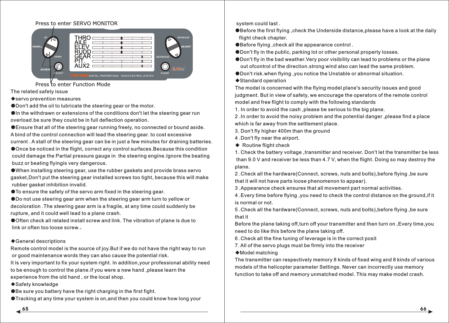
![37 38◇To Access the Timing FunctionPress the DOWN and SELECT keys simultaneously to access the system mode.In System Mode, use the UP or DOWN key to select the TIMER screen.Press the SELECT key to select STOP-W, DOWN-T or INH.With DOWN-T selected press the INCREASE or DECREASE key to change the preprogrammed time.◇To Access the Timing Control and Switch FunctionPress the DOWN and SELECT keys simultaneously to access the system mode.In System Mode, use the UP or DOWN key to select the TIMER screen.Press the SELECT key to select STOP-W, DOWN-T or INH key or switch.With STOP-W selected, press the INCREASE or DECREASE key to select the key and switch.Press the DOWN and SELECT keys simultaneously to access the system mode.In System Mode, use the UP or DOWN key to select the TIMER screen.Press the SELECT key to select STOP-W, DOWN-T or INH.With DOWN-T selected press the INCREASE or DECREASE key to change the preprogrammed time.After choosing the countdown timer and press INCREASE or DECREASE key to change the good programming time in advance.◆Servo MonitorThe servo monitor screen serves as a useful tool when programming your radio. It displays servo positions and is useful in checking different programming functions.TEN, Helicopter Programming guideTransmitter Control Identification and LocationMODEL 110.6V12.5ms FRAME RATEDOWN-T10:00Press the INCREASE or DECREASE Press the CLEAR key to reset the timerkey to start or stop the timerMODEL 110.6V12.5ms FRAME RATEDOWN-T10:00Press the INCREASE or DECREASE Press the CLEAR key to reset the timerkey to start or stop the timerTHROAILEELEVRUDDGEARFLAPAUX2Press to enter SERVO MONITORPress to enter Function ModePress to select TIMERPress to enterFunction ModePress the CLEAR keyto reset the DOWN-TPress the SELECT keyto access INH, DOWN-Tor STOP-WPress the INCREASE or DECREASEkey to set the down timer[ TIMER ]MODEL 1DOWN-T00:00SW:ADJUST](https://usermanual.wiki/Xingyaohua/T7AH-2400/User-Guide-1601195-Page-20.png)
![41 42[SWASH TYPE]1 SERVONORMSwash Type (Page 49)[THRO RECOVERY]INHThrottle Recovery (Page 46)Model Select (Page 43)SELECTMODEL 1HELI [MODE SELECT]Model Name (Page 43)[MODEL NAME]MODEL 1 HELI < > Input Select (Page 47)[INPUT SELECT]AUX2 GEARGYRO GEARType Select (Page 44)[TYPE SELECT]MODEL 1HELIACROModel Reset (Page 45)[MODEL RESET]MODEL 1 HELI DATA RESETINTEG-T03:00:34◇To Enter the System Setup Mode● With the power switch off, press the DOWN and SELECT keys simultaneously.● Turn on the power switch.● The system will display the last system setup screen that was used.◇To Exit the System Setup Mode● Press the DOWN and SELECT keys simultaneously.● The main menu will be displayed● Or turn the transmitter off to exit the System Setup Mode◆Model Select/CopyThe T7AH-2400 features a memory function that stores the programmed data for up to 6 models. Any combination of up to 6 airplanes and/or helicopters can be stored in memory. A model name feature with up to eight characters allows each model to be easily identified.◇To Enter the Model Select FunctionPress the DOWN and SELECT keys simultaneously, then turn the power switch on to access the System Setup Mode. Press the INCREASE or DECREASE key until the MODEL SELECT appears on screen.Press the INCREASE or DECREASE key to select the desired model memory.MODEL 112.5ms FRAME RATE10.6VINCREASE and DECREASE keyUP and DOWN keyHOLD while turning on transmitter CLEAR key[MODEL SELECT ]SELECTMODEL 1 T-REX ACRO Hold while turning on transmitter UP and DOWN key INCREASE and DECREASE key[MODEL SELECT]MODEL 1HELI MODEL 2ACRO COPYINCREASE and DECREASE keyPress to select MODEL SELECTPress to enterfunction main screenPress to enterCOPY screenPress to copyselected model[SKMODE SELECT]ELEVRUDDTHROAILEMODE 1Stick mode select(Page 19)[CHNO ASSGIN]1:THRO2:AILE3:ELEV4:RUDD5:GEAR6:PIT.7:AUX2Channel no assign(Page 19)[TRAINER]INH Throttle Recovery (Page 46)](https://usermanual.wiki/Xingyaohua/T7AH-2400/User-Guide-1601195-Page-22.png)
![43 44◇To Enter the Copy Function● Press the DOWN and SELECT keys simultaneously and turn the power switch on to access the System Setup Mode.● Press the UP or DOWN key until MODEL SELECT appears on screen.● Press the SELECT button to enter the COPY screen.● Press the INCREASE or DECREASE keys to select to model that you wish to copy the model.● Press the CLEAR key to copy the model to the selected model memory.Note: Be aware that the model that you copy will have its memory replaced with the new model and the programming information for that model will be erased.◆Model NameThe Model Name function is used to input and assign the model's name to a specific memory, allowing easy identification of each model's program. Each model's name is displayed on the main screen when that model is selected. Up to eight characters and numbers are available.◇To Enter the Model Name FunctionPress the DOWN and SELECT keys simultaneously, then turn on the transmitter.Press the INCREASE or DECREASE key until the MODEL NAME screen appears.Press the SELECT Key to move the cursor to the desired character's position.Press the INCREASE or DECREASE key to select the desired character. ◆Type Select FunctionThe T7AH-2400 features two programming types: Airplane and Helicopter. The T7AH-2400 can memorize data for up to 6 models individually.◇To Enter the Type Select ModePress the DOWN and SELECT keys simultaneously, then turn on the transmitter.Press the UP key until the TYPE SELECT function appears on screen.◇To Select a Model TypePress the INCREASE or DECREASE key to change between the heli or acro model types.To accept the new model type by pressing the CLEAR key. ◆Model Reset/Integrated TimerThe Model Reset function resets all programming functions to their default settings. This screen also allows you to reset the integrated timer function to zero.[TYPE SELECT]MODEL 1HELIINCREASE and DECREASE keyPress to enter TYPE SELECTHold while turning on transmitterACRO[MODEL NAME ]MODEL 1 ACRO (T-REX450)Press to enter MODEL NAME INCREASE and DECREASE keyPress to enter main screen[TYPE SELECT]MODEL 1HELIINCREASE and DECREASE keyACROYES CLEAR KEYPress to accept new model type](https://usermanual.wiki/Xingyaohua/T7AH-2400/User-Guide-1601195-Page-23.png)
![45 46◇To Reset a Model● Press the DOWN and SELECT keys simultaneously, then turn on the transmitter.● Press the UP key until MODEL RESET appears on screen.● Press the SELECT key until DATA RESET is highlighted. ● Pressing the CLEAR key will reset the model memory to factory default settings.◇To Reset the Integrated Timer● Press the DOWN and SELECT keys simultaneously, then turn on the transmitter.● Press the UP key until the MODEL RESET function appears on screen.● Press the SELECT key until INTEg-T is highlighted.● Pressing the CLEAR key will reset the INTEG-T to factory zero.◆Enhanced wireless TrainerThe T7AH-2400 offers a Wireless Trainer Function. Premise is the transmitter's and transmitter's sets are the same.To Enter the Trainer Mode:Press the DOWN and SELECT keys simultaneously, then turn on the transmitter.Press the UP key until TRAINER function appears on screen.Press the INCREASE or DECREASE key to activate or close Trainer function, then TRAINER TRIM only used as a trainer switches.◆Throttle RecoveryThe T7AH-2400 has a unique throttle trim recovery feature. Throttle Recovery stores the last known throttle trim position once throttle restore function is activated. That stored position is then recalled by moving the throttle trim up (open) one notch when the throttle trim is moved to the full down (closed) position. This makes shutting off the engine and restarting it with the correct trim position easy.To Activate the Throttle Recovery FunctionPress the DOWN and SELECT keys simultaneously, then turn on the transmitter.Press the UP key until THRO RECOVERY appears on screen.Press the INCREASE or DECREASE key to turn on/off the Throttle Recovery function.◇To Activate the Throttle Recovery FunctionPress the DOWN and SELECT keys simultaneously, then turn on the transmitter.Press the UP key until THRO RECOVERY appears on screen.Press the INCREASE or DECREASE key to turn on/off the Throttle Recovery function.[MODEL RESET]MODEL 1 ACRO DATA RESETINTEG-TPress to enter MODEL RESETHold while turningon transmitterPress to selectRESET or INTEG-TPress to resetdata or timer00:00:34[MODEL RESET]MODEL 1 ACRO DATA RESETINTEG-TPress to enter MODEL RESETHold while turningon transmitterPress to selectRESET or INTEG-TPress to resetdata or timer00:00:34INCREASE and DECREASE keyINCREASE and DECREASE keyPress to enterfunction main screenPress to enterCOPY screenPress to copyselected modelINHTRAIN RECOVERY [ ]Press to enter THROTTLE RECOVERY◆Pole modeThe T7AH-2400 have in four different control rod "mode" (0, 1, 2, 3). Different mode corresponding to operation function of different control rod. Usually, set in "mode" 1.](https://usermanual.wiki/Xingyaohua/T7AH-2400/User-Guide-1601195-Page-24.png)
![47 48Change the channel distributePress the SELECT and DOWN keys simultaneously and turn the transmitter on.Press the UP key until CHNO ASSGIN appears on screen.Press the SELECT key to select channel that you wish to output signal.Press the INCREASE or DECREASE key to change the signal out putted by channel. Press the CLEAR key restoring default values.◆Input SelectThe Input Select function is used to select the switch input for the gyro gain and the channel that will operate.To Select the Function for the AUX2 ChannelPress the DOWN and SELECT keys simultaneously, then turn on the transmitter.Press the UP or DOWN key until the INPUT SELECT function appears on screen.Press the SELECT key until AUX2 is highlighted.Press the INCREASE or DECREASE key to select the desired function.◇To Select the Function for the Gear ChannelPress the DOWN and SELECT keys simultaneously, then turn on the transmitter.Press the UP or DOWN key until INPUT SELECT appears on screen.Press the SELECT key until GEAR is highlighted.Press the INCREASE or DECREASE key to select the desired function.The gear channel options are:INH: Inhibit is selected if the gyro function will not be used on the gear channel. Selecting inhibit turns off the channel, allowing it to be used as a slave channel fo mixing.INCREASE and DECREASE keyPress to enter INPUT SELECTHold while turning on transmitter[INPUT SELECT]AUX2 GEARGYRO INHINCREASE and DECREASE keyPress to enter INPUT SELECTHold while turning on transmitter[INPUT SELECT]AUX2 GEARINH INHPress to reset[SKMODE SELECT]MODE 1ELEVRUDDTHROAILEChange Pole mode Press the DOWN and SELECT keys simultaneously, the turn the transmitter on. Press the UP key until SKMODE SELECT appear on green. Press the INCREASE and DECREASE keys to change the pole mode.The T7AH-2400 can assign 7 channels to output in any channel, you can choose a different style of the channel allocation, can also customize the output channel allocation output.[CHNO ASSGIN]1:THRO2:AILE3:ELEV4:RUDD5:GEAR6:FLAP7;AUX2The Auxiliary 2 channel options are:INH: Inhibit is selected if the gyro function will not be used on the Aux 2 channel.F.MODE: In this mode, the AUX2 channel is controlled by the flight mode switch and three positions are available. Sub trim and travel adjust is used to set the center and end points for each switch position. AUX2: The Auxiliary 2 switch controls the AUX2 Channel.GYRO: The gyro mode is selected if you want to use the Gyro Sensing (see page 96) for more detail. Selecting GYRO under AUX2 assigns the gyro sensing program to operate use the AUX2 channel. In this case the gyro gain must be plugged into the AUX2 (Channel 7) channel.](https://usermanual.wiki/Xingyaohua/T7AH-2400/User-Guide-1601195-Page-25.png)
![49 502 Servo/180 CCPM 3 Servo/120 CCPM(most popular) 3 Servo/90 CCPM Ch6Ch2Ch3Ch2 Ch6Ch3Ch2 Ch6◇Accessing the Swashplate TypesWhile pressing the DOWN and SELECT keys, turn the transmitter on to enter the System Mode.Press either the UP or DOWN key until SWASH TYPE is displayed in the LCD.Press the INCREASE or DECREASE keys to change the swashplate type.Pressing the CLEAR key will reset the swashplate type to the NORMAL position.[AUTO D/R EXP]NORM INHST-1 INHST-2 INH[D/R & EXP]POS-0AILED/R 100%EXP LINOUTPUT[SUB TRIM]THRO AILE0 00 0ELEV RUDD[REVERSING SW]NORMGEARch 1 2 3 4 5 6 7REV.[SWASH MIX]3 SERVO120EXP INH AILE + 60%ELEV + 60%PIT. + 60%[TRAVEL ADJUST]THROH 100%L 100%ELEVD 100%U 100%AILE L 100%R 100%RUDDL 100%R 100%THROAILEELEVRUDDGEARFLAPAUX2[TIMER]MODEL 1DOWN-T10:00[PROG.MIX1]THRO THRO ONRATE: 0%0%SW:ONOFFSET: 0[REVO MIX]NORM STNTUP 0%DN 0%UP 0%DN 0%[GYRO SENS]RUDDRATE:0: 50%1: 50%[THRO HOLD]HOLD POS.ACT OFF- 5.0%[THRO CURVE]ST-1Point-351 51INH1 2 3HLIN OUT[THRO CURVE]NORMPoint-L 51 510.0%1 2 3 HLIN OUT[PITCH CURVE]HOLD Point-L49 490.0%1 2 3HLIN OUT[PITCH CURVE]ST-1Point-351 51INH1 2 3HLIN OUT[PITCH CURVE]ST-2 Point-351 51INH1 2 3HLIN OUT[THRO CURVE]ST-2 Point-351 51INH1 2 3HLIN OUT[PITCH CURVE] Point-351 51INH1 2 3HLINTravel Adjust(56 )Page Auto Dual Rate Expo(54 )PageDual Rate &Exponential(51Page)Programmable Mix (1 though 3)(64 )PageSub Trim (55 )PageReverse(54 )PageSwashplate Mix (Only available whenCCPM Mix is active(56 )PageThrottle Hold(57 )PageNORMALhrottle Curve Normal(58 )PageThrottle Curve ST-1Throttle Curve ST-2Pitch Curve NormalPitch Curve ST-2Pitch Curve Hold (only available when HOLD is activated)Revo Mix(6 0 )PageGyro Sensing (Only available when AUX2 or GEAR is assigned as Gyro Function)(60 )PageServo Monitor (61 )PageTimer(6 3 )PagePress to enter SWASH TYPE Press to welect Wwashplate TYpeHold white turning on the transmitter[SWASH MIX]1 SERVONORM◆Swash TypeThe Swashplate Mixing function enables the DX7 system to operate the following swashplate types:The Swashplates are:● 1 Servo: Non-CCPM, standard mixing type helicopter● 2 Servo/180° CCPM● 3 Servo/120° CCPM (most popular)● 3 Servo/90° CCPMGYRO: Gyro is selected under gear if you wish to have the Gyro Sensing (see Page 96 to gain more detail) operate using the gear channel.AUX2: The Auxiliary 2 switch is used to activate the gear channel.10.2 Function Mode FlowchartThe following function Mode programming includes more programming functions that are frequently used. Pitch Curve ST-110.2 flow chart of function mode:the following programming of function mode, more common usage inclusive.](https://usermanual.wiki/Xingyaohua/T7AH-2400/User-Guide-1601195-Page-26.png)
![51 52◇To Enter the Function Mode● Turn the transmitter on.● From the main screen press the DOWN and SELECT keys simultaneously.● The system is now in Function Mode and will display the last screen that was used in Function Mode.◇To Exit the Function Mode● Press the DOWN and SELECT keys simultaneously. The system will return to the main screen.◆List ModesThe list mode screens display all the functions on screen, allowing the access of any function without having to scroll through each screen. Note that there are two list modes: a System Setup list mode that displays all the system setup functions and a Function list mode that displays all the system programming functions.To enter the System Setup List Mode, with the system on and in any System Setup function, press the UP and SELECT keys simultaneously.To enter the Function List mode, with the system on and in any function mode screen, press the UP and SELECT keys simultaneously.In either List Mode, pressing the UP and DOWN keys will move the cursor to the desired function. Then pressing the DOWN and SELECT key simultaneously will access the selected function.10.3 Function Mode Functions◆Dual Rate and ExponentialThe Dual Rate and Exponential function allows two control rates to be programmed and selected with a switch. Dual rates and exponentials are available on the aileron, elevator and rudder channels. Changing the dual rate value not only affects the maximum control authority but also affects the overall sensitivity of control. A higher rate yields a higher overall sensitivity.Dual rates can be controlled by their respective dual rate switches (aileron, elevator and rudder). An auto dual rate function is available that allows to automatic selection of the desired rates via the three-position flight-mode switch.Exponential values are adjustable from -100% to +100%. The factory default settings for both the 0 and 1 switch positions are 100%. Either switch position may be selected as the low or high rate by placing the switch in the desired position and adjusting the value accordingly.[FUNCTION LIST]D/R & EXPAUTO D/RSWASH MIXREV. SWSUB TRIMTRAV ADJ. PI CURV ST1THRO HOLDTH CURV NORTH CURV ST1TH CURV ST2PI CURV NORASE and DECREASE keyUP and DOWN keySELECT key CLEAR key PI CURV NORINCREASE and DECREASE key[FUNCTION LIST]PI CURV ST2PROG.MIX2REVO. MIXGYRO SENSPROG.MIX1PROG.MIX3TIMERUP and DOWN keySELECT key CLEAR keyMONITOR[D/R & EXP]POS-0AILED/R 100%EXP LINOUTPUTPress to adjust valuePress to enter DUAL Press to enterFunction ModeRATE and EXPONENTIALPress to select desired functionPress to return value to default setting[D/R & EXP]POS-0D/R 100%EXP LINOUTPUTINCREASE and DECREASE keyUP and DOWN keyPress to enterFunction ModeAILE](https://usermanual.wiki/Xingyaohua/T7AH-2400/User-Guide-1601195-Page-27.png)
![53 54The Exponential function allows two exponential rates to be programmed and selected with a switch. Exponential is available on the aileron, elevator and rudder channels. Changing the exponential value does not affect the maximum control authority but only affects control sensitivity. Exponential is normally used to reduce control sensitivity around neutral while still allowing high control authority at the extremes of throw. The sensitivity around center can be tailored using the Exponential function to precisely adjust control feel.Exponential rates can be controlled by their respective rate switches (aileron, elevator and rudder), or combined on a flight mode switch. Exponential is available for the aileron, elevator and rudder channels. Expo values are adjustable from -100% (full negative expo), LIN (linear), and +100% (full positive expo). The factory default settings for both the 0 and 1 switch positions are LIN or 0%. Either switch position may be selected to give any desirable EXPO rate by placing the switch in the desired position and adjusting the value accordingly.Note: A negative (-) Expo value will increase sensitivity around neutral, and a positive (+) Expo value will decrease sensitivity around neutral. Normally a positive value is used to insensitize control response around neutral.◇To Adjust the ExponentialPress the DOWN and SELECT keys simultaneously to access the Function Mode.In Function Mode, use the UP or DOWN keys to select the DUAL RATE AND EXPONENTIAL screen.Press the INCREASE or DECREASE key to select the desired channel (AILE, ELEV or RUDD).Move the selected channel's dual rate switch to the desired position, 0 or 1.Press the SELECT key until EXP is highlighted.Adjust the Expo rate values for the selected switch position using the INCREASE or DECREASE keys.◆Auto Dual Rate EXPThe Auto Dual Rate and Expo function allows Expo and Dual Rate values (aileron, elevator and rudder) to be automatically selected in each flight mode (Normal, ◇To Adjust the Auto Dual RatePress the DOWN and SELECT key simultaneously to access the Function Mode.Press the UP or DowN key until the AUTO D/R EXP screen appears on screen.Use the select key to select NORMAL, ST1 ST2 or NORMAL mode.When selected, press the INCREASE or DECREASE key to select DUAL RATE, P-1, P-2 or INHIBIT.Note: The actual dual rate values are setted in the Dual Rate and Expo screen. See Page 84.◆Reverse SwitchThe Reverse Switch function allows electronic means of reversing the servo’s throw. Servo reversing is available for all seven channels.◇Accessing the Reverse Switch FunctionPress the SELECT key to access the desired channel.Press the INCREASE or DECREASE keys to reverse the servo direction for thatselected channel.[D/R & EXP]POS-0AILED/R 100%EXP LINOUTPUTPress to adjust valuePress to enter DUAL Press to enterFunction ModeRATE and EXPONENTIALPress to select desired functionPress to return value to default setting[AUTO D/R & EXP]NORM INHST-1 INHPress to adjust valuePress to enter Press to enterFunction ModePress to select desired flight modePress to return value AUTO DUAL RATE to default settingST-2 INH[REVERSING SW]NORMGEARch 1 2 3 4 5 6 7 REV.Press to select REV. or NORMPress to enter REVERSEPress to enterFunction ModePress to selectdesired channelSt1, ST2, and Hold.) When an auto dual rate flight mode is inhibited, the dual rateis defaulted to the correlating switch and dual rate switch positions.](https://usermanual.wiki/Xingyaohua/T7AH-2400/User-Guide-1601195-Page-28.png)
![55 56● THRO: Throttle ● AILE: Aileron ● ELEV: Elevator ● RUDD: Rudder● GEAR: Gyro Gain ● PIT: Pitch (AUX1) Gyro Gain◆Sub TrimThe Sub-Trim function allows you to electronically adjust the centering of each servo. Sub trim is individually adjustable for all seven channels, with a range of + or - 125% (+ or – 30 degrees servo travel).Caution: Do not use excessive sub-trim values as it is possible to overdrive the servo’s maximum travel. Sub-trim value (max ±125).The available channels are:● THRO: Throttle ● AILE: Aileron ● ELEV: Elevator● RUDD: Rudder ● GEAR: Retractable Landing Gear● PIT.: Pitch ● AUX2: Auxiliary 2◇To Access the Sub-Trim FunctionPress the DOWN and SELECT keys simultaneously to access the Function Mode.In Function Mode, use the UP or DOWN key to select the SUB TRIM screen.Press the SELECT key to access the desired channel.Press the INCREASE or DECREASE keys to adjust the sub-trim position for that selected channel. ● ELEV: Elevator● RUDD: Rudder● GEAR: Retractable Landing Gear● PIT.: Pitch● AUX2: Auxiliary 2 ◇To Access the Travel Adjust FunctionPress the SELECT key to access the desired channel.Move the selected channel’s Stick or switch in the desired direction that you wishto adjust. ◆The screen of the swash mix only showes when is activited. swash mix can adjust the quantity and direction of the aileron trip,elevator and rudder.For example,if more aileron trips are selected ,adding the mixed value will increase the necessary whole trip of steer to get more aileron distance.NOTE: The use of a negative value will reverse the direction of the function2 Servo/180 CCPM 3 Servo/120 CCPM(most popular) 3 Servo/90 CCPM Ch6Ch2Ch3Ch2 Ch6Ch3Ch2 Ch6Press to enter SUB TRIM Press to adjust sub-trim positionFunction ModePress to enter [ SUB TRIM ]Press to selectDesired channelTHRO AILE0 0ELEV RUDD0 0[TRAVEL ADJUST]THRO H 100%L 100%ELEVD 100%U 100%AILE L 100%R 100%RUDDL 100%Selected channelPress to enterTRAVEL ADJUSTPress to enterFunction ModePress to returnvalue to defaultPress to selectdesired channelR 100%Press to adjust value◆Travel AdjustThe Travel Adjust function allows the precise end point adjustments of all seven channels in each direction independently. The travel adjust range is from 0–125%.Channel available for programming are:● THRO: Throttle● AILE: Aileron](https://usermanual.wiki/Xingyaohua/T7AH-2400/User-Guide-1601195-Page-29.png)
![57 58◇Accessing the Swashplate Mix FunctionPress the DOWN and SELECT keys simultaneously to access the Function Mode.In function mode, press the UP or DOWN key to select the SWASH MIX screen.Press the SELECT key to access the desired function (AILERON, ELEVATOR, PITCH or EXPO).Press the INCREASE or DECREASE key to change the selected swashplate mix value.Note: Selecting a negative value will reverse the direction of the function.Note:The cross plate's exponential function can be used,the compensation for non linear output is caused by the loop servo's rotation. The exponential function can eliminate the cross plate interaction in extreme times.◆Throttle HoldThe Throttle Hold function is used to practice autorotation and is often use as a safety switch for electric helicopters, holding the throttle in the off position. When the throttle hold switch is activated, the throttle hold function holds the throttle servo/ ESC in a specific position (normally low or off throttle) while all other servos function normally. The throttle hold switch is also selectable. Switch selection options include rudd D/R, gear, AUX2, aileron D/R or elevator D/R.◇To Access the Throttle Hold FunctionPress the DOWN and SELECT keys simultaneously to access the Function Mode.In Function Mode, use the UP or DOWN key to select the THRO HOLD screen.Press the INCREASE or DECREASE key to activate the throttle hold function.When activated, press the INCREASE or DECREASE key to change the throttle hold value.◇To Access the Throttle Hold Switch FunctionPress the SELECT key to highlight switch.Press the INCREASE or DECREASE key to select the desired switch.◆Throttle CurveThe T7AH-2400 offers three (3) separate throttle curves with five (5) adjustable points per curve. This function allows you to adust the throttle curve to optimize engine rpm at a particular pitch setting. Once the throttle curves are established, each can be activated in flight using the 3-position flight mode switch. The flight mode switch offersthree (3) selectable curves: N=Normal, 1=Stunt 1, 2=Stunt 2.The N, or Normal, position should be used for starting the engine and hovering. Positions 1 and 2, or Stunt 1 and Stunt 2, should be used for aerobatic maneuvers and forward flight.Note: The throttle trim and hovering throttle lever are only operable when the flight mode switch is in the Normal position. Thus, in the 1 or 2 positions, these two functions have no effect. Each of the five (5) positions of the throttle curve are independently adjustable from 0–100%. These five (5) positions correspond to the position of the throttlestick.The transmitter is factory preset to the throttlecurve as indicated by the solid line in the figure below. Individual points can be activated and increased/decreased to suit your specific needs.◇To Access the Throttle Curve FunctionPress the DOWN and SELECT keys simultaneously to access the System Mode.Press to enter SWASH MIX Press to adjust valueHold white turning on the transmitter[SWASH MIX]3 SERVO120EXP INHAILE+ 60%ELEV+ 60%PIF. + 60%Press to resetvalue to default[THRO HOLD]SW:RUDD D/RHOLD POS. -5.0%Press to enterTHROTTLE HOLDPress to enterFunction ModePress to returnvalue to INHPress to selectdesired channelPress to activate THROTTLE HOLDand change valuesPress to adjust values[THRO CURVE]NORMPoint-L51 510.0%1 2 3 HLIN OUT Press to enterTHROTTLE CURVEPress to enterFunction ModePress to selectdesired pointsPress to return value to default](https://usermanual.wiki/Xingyaohua/T7AH-2400/User-Guide-1601195-Page-30.png)
![59 60◆Pitch CurveAdjustment of the pitch curve is very similar to the throttle curve adjustment described in the preceding section. A thorough understanding of the throttle curve section will make pitch curve adjustment easier to understand.The T7AH-2400 offers four (4) independent pitch curves: Normal, Stunt 1, Stunt 2 and Hold. Each pitch curve contains five (5) adjustable points — L, 1, 2, 3, and H.Note: When setting pitch curve for throttle hold, it is necessary for the throttle hold to be active. if this function is inhibited, the throttle hold pitch curve will not be visible on the screen.◇To Access the Pitch Curve FunctionPress the DOWN and SELECT keys simultaneously to access the System Mode.In System Mode, use the UP or DOWN keys to select the PITCH CURVE NORM screen. Press the SELECT button to access pitch points L (Low), 1, 2, 3, or H (High) or EXPO.Press the INCREASE or DECREASE keys to change the selected pitch value or expo on/off.◆Hovering Pitch RockerThe hovering pitch rocker operates in the same manner as the hovering throttle rocker. It is operable while the flight mode is in the N, or Normal, position, and its function is to shift the center point (#2) of the curve either upward or downward to adjust pitch at the hover position.◆Revolution Mixing (only used with non-heading hold gyros)The Revolution Mixing Function mixes tail rotor input with the Throttle/Collective function to counteract torque from the main rotor blades. When set up correctly, the helicopter should climb and descend without a tendency to yaw in either direction. Because torque reaction varies with different power settings, it is◆Setting Up Revolution MixingFirst, adjust the helicopter so that it will hover in a neutral position with the tail rotor trim at center. Next, establish the helicopter into a stable hover; then steadily increase the throttle to initiate a stable climb. The body of the helicopter will move in the opposite direction to the main rotor rotation. Increase the U, or Up, settinguntil the helicopter will climb with no tendency to turn or rotate. At a safe altitude, close the throttle and the helicopter will descend with the body turning in the same direction as the main rotor. Increase the D, or Down, mix until the helicopter descends with no tendency to turn or rotate. When attempting this procedure, throttle stick movements should be slow, and the initial acceleration and deceleration swings should be overlooked.。◇To Access Revolution MixingPress the DOWN and SELECT keys simultaneously to access the Function Mode.Press the SELECT key to select the desired function.Press the INCREASE or DECREASE key to change the value or function.◆Gyro SensingThe T7AH-2400 offers two different types of Gyro Sensitivity Adjustments — manual or automatic. This feature gives the user the choice of selecting gyro sensitivitymanually through the rudder dual rate switch or automatically through the flight mode switch.[ REVO MIX ]Press to enter REVO MIXPress to enterFunction ModePress to selectdesired channelPress to return value to defaultNORM STNTUP 0% UP 0% DN 0% DN 0% Press to adjust values[PITCH CURVE] NORMPoint-351 51INH1 2 3HLIN OUT Press to enterTHROTTLE CURVEPress to enterFunction ModePress to selectdesired pointsPress to return value to defaultIn System Mode, use the UP or DOWN keys to select the THRO CURVE NORM screen.Press the SELECT button to access pitch points L (Low), 1, 2, 3, or H (High) or EXPO.Press the INCREASE or DECREASE keys to change the selected pitch value or expo on/off. necessary to vary the tail rotor pitch at the same time. The DX7 offers two (2) separate revolution mixing programs with independent up and down mixing for each—one for flight mode position N, and the other for Stunt 1 and Stunt 2 positions. The U, or Up, mixing adjusts the tail rotor compensation for the mid to high throttle/stick setting, and the D, or DOWN, mixing adjusts the tail rotor compensation for the mid to low throttle/stick setting.In the Function Mode, use the UP or DOWN keys to select Revolution Mixing screen.!!](https://usermanual.wiki/Xingyaohua/T7AH-2400/User-Guide-1601195-Page-31.png)
![61 62◇To Access the Gyro Sensing FunctionIn function mode, press the UP or DowN key until gYRO SENS screen appears on the screen.Use the SELECT key to highlight the desired RATE or FLIgHT MODE.Press the INCREASE or DECREASE key to change the rate value or the select position 0 or 1 for each flight mode.Note: In order to access the Gyro Sensing function, it is necessary to select Gyro in the Input Select screen and assign it to AUX2 or the gear channel. See Page 78 for more details.◆Manual Gyro Sensitivity AdjustmentManual Gyro Sensitivity Adjustment allows the pilot to select from two different gyro sensitivities during all flight conditions. This function is activated in conjunction with the rudder dual rate switch.◆Automatic Gyro Sensitivity AdjustmentThe Automatic Gyro Sensitivity Adjustment feature allows the pilot to automatically alter the sensitivity of the gyro from either of two pre-determined settings through the use of the flight mode switch. As different flight modes are selected (Normal, 1, 2, Hold), the Gyro’s sensitivity rate will switch to the pre-determined compensation rate for each particular flight mode in use. [ PROG.MIX1 ]Press to enter PROG MIXPress to enterFunction ModePress to return value to defaultRATE: 0%SW:ON 0% THRO THRO ONOFFSET: 0Press to highlightPress to adjust mix valueRATE[ PROG.MIX1 ]Press to enter GYRO SENSPress to enterFunction ModePress to return value to defaultRATE: 0%SW:ON 0% THRO THRO ONOFFSET: 0Press to highlightMASTER CHANNELor SLAVE CHANNEL[ ]GYRO SENSPress to enter GYRO SENSPress to enterFunction ModePress to selectdesired functionPress to return value to defaultRATE:1:50% 0:50% AUTO F.MODE NORM:0STNT:0◆Programmable Mixing 1–3In helicopter mode the T7AH-2400 offers three (3) programmable mixes that allow stick or switch inputs to control the output of two or more servos. This function allows mixing any one channel to any other channel or the ability to mix a channel to itself. The mix can remain ON at all times, or be switched OFF in flight using a number of different switches. (Refer to chart below.) Mix values are adjustable from 0 to 125%. Each channel is identified by a four-character name (i.e., Aileron - AILE, Elevator - ELEV, etc.). The channel appearing first is the master channel. The second channel is the slave channel. For example, AILE - ELEV would indicate aileron-to-elevator mixing. Each time the aileron stick is moved, the elevator will deflect, and the elevator will automatically move in the direction and to the position based on the value input in the programmable mix screen. Mixing is proportional, so small inputs of the master channel will produce small outputs of the slave channel. Each programmable mix has a mixing offset. The purpose of the mixing offset is to redefine the neutral position of the auxiliary channel.● ON: Mixing always on ● F-NR: Flight mode normal● F-S12: Stunt modes 1 and 2 ● F-S2: Stunt mode 2● HOLD: Throttle hole toward self ● GEAR: Gear channel toward self◆Assigning ChannelsPress the DOWN and SELECT keys simultaneously to access the Function Mode.In Function Mode, use the UP or DOWN keys to select the desired PROG. MIX screen (1–3). Press the INCREASE or DECREASE button to access the Programmable Mix function.Press the INCREASE or DECREASE keys to selectthe desired master channel.Press the SELECT key to highlight the auxiliary channel.Press the INCREASE or DECREASE keys to select the desired slave channel.◇Assigning Mixing ValuesPress the DOWN and SELECT keys simultaneously to access the Function Mode.In Function Mode, use the UP or DowN keys to select the desired PROg. MIX screen (1–3).Press the SELECT key to highlight RATE.Using the stick or switch that is assigned to the master channel, move that stick or](https://usermanual.wiki/Xingyaohua/T7AH-2400/User-Guide-1601195-Page-32.png)
![63 64MODEL 110.6V12.5ms FRAME RATEDOWN-T10:00Press the INCREASE or DECREASE Press the CLEAR key to reset the timerkey to start or stop the timerPress to select TIMERPress to enterFunction ModePress the CLEAR keyto reset the DOWN-Tto 10:00 minutesPress the SELECT keyto access INH, DOWN-Tor STOP-WPress the INCREASE or DECREASEkey to set the down timer[ TIMER ]MODEL 1DOWN-T00:00SW:ADJUST[ PROG.MIX1 ]Press to enter PROG MIXPress to enterFunction ModePress to return value to defaultRATE: 0%SW:ON 0% THRO THRO ONOFFSET: 0Press to adjust mix valuePress to highlight OFFSET switch in the desired direction that you wish to adjust the mix value. Press the INCREASE or DECREASE keys to adjust the mix value.Note: If a switch is assigned to the mix, that switch must be turned on to allow mixing values to be changed.Moving the stick or switch in the opposite direction will allow the mix value to be adjusted in the opposite direction.◆Assigning an OffsetPress the DowN and SELECT keys simultaneously to access the Function Mode.In Function Mode, use the UP or DOWN keys to select the desired PROG. MIX screen (1–3).Press the SELECT key to highlight OFFSET.Press the INCREASE or DECREASE key to select the desired offset value.◆TimerT7AH-2400 provides a screen show timer.with three programmable SettingsINH:Shielding-in this mode timer is closedDOWN-T:Countdown timer-decreasing order of default timer which allowed 10 seconds of interval to 59 points 50 seconds was programming. When that time expires before 10 S, every 1 S have a sound, a total of 10 times.STOP-W:Stopwatch-a stopwatch function is a simple count timer, display up to 59 points 59] seconds. When that time expires, the top 10 S. Every 1 s have a sound, a total of 10 timesWhen the countdown timer and stopwatch function is selected, the timer will display in the main screen. The following button or switch is to start or stop the timer.SW: ADJUST ADJUST button FLTNOR Flight mode NORMAL ELE D/R Elevator double proportion GEAR GEAR AUX2 AUX2 AILE D/R Aileron double proportionRUDD D/R Direction listed the campaign of THROHOLD Throttle keepCLEAR buttons:Used to reset timers to the default time or reset a stopwatch to 0-0FLT12 Flight mode 1、2 ◇Access to the timer functionPress the DOWN and SELECT buttons simultaneously to enter the system mode.In system mode, the use UP or DOWN keys to select the timer screenAccording to the SELECT button to choose a stopwatch, countdown timer or stopAfter choosing the countdown timer press INCREASE or DECREASE button to change the programming in advance.◇Access the timer control buttons or switch functionPress the SELECT and the DOWN buttons simultaneously to enter the system modeIn system mode, to use UP or DOWN keys to select the TIMER screen.Press the SELECT button to choose SW,,start or stop the timer buttons or switchAfter choosing the SW and then to press INCREASE or DECREASE keys to selector buttons or switch.Server displayServer display screen is used as a useful tool when programming your remote control. It shows the steering gear's moving and direction when different programming function, the joystick or switch moves.](https://usermanual.wiki/Xingyaohua/T7AH-2400/User-Guide-1601195-Page-33.png)