Xircom EAG2919 Eagle II 900/1900 MHz GSM Radio Module User Manual
Xircom Eagle II 900/1900 MHz GSM Radio Module Users Manual
UserManual.wiki
>
Xircom
>
EAG2919 User Manual
Users Manual
Navigation menu
Upload a User Manual
Namespaces
Wiki Guide
HTML
PDF
Info
Views
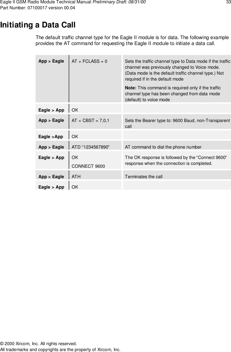
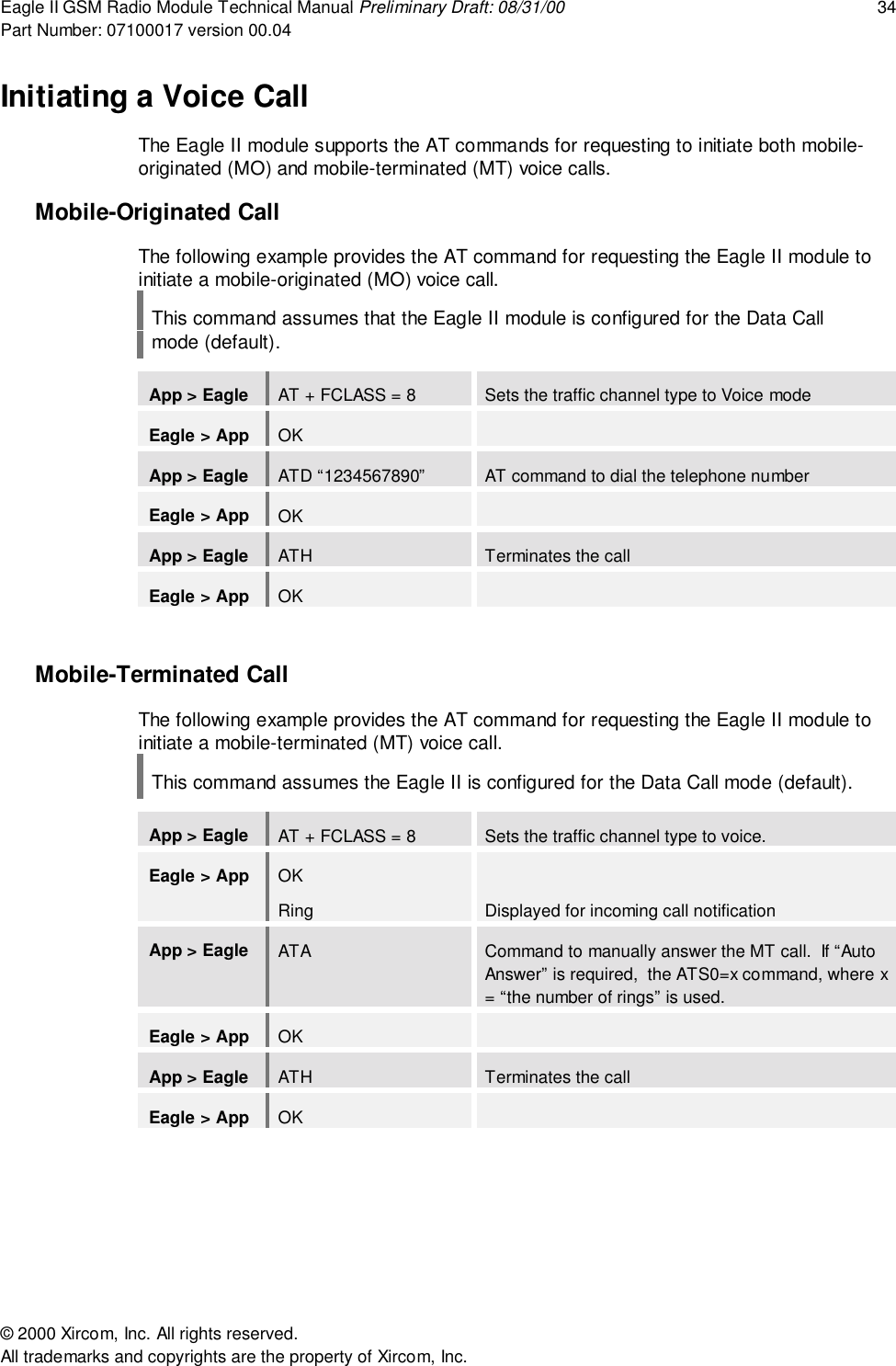
User Manual
Discussion / Help
Navigation