YDT Technology A800 RFID Reader User Manual rev
YDT Technology International Co. Ltd RFID Reader rev
UserManual.wiki
>
YDT Technology
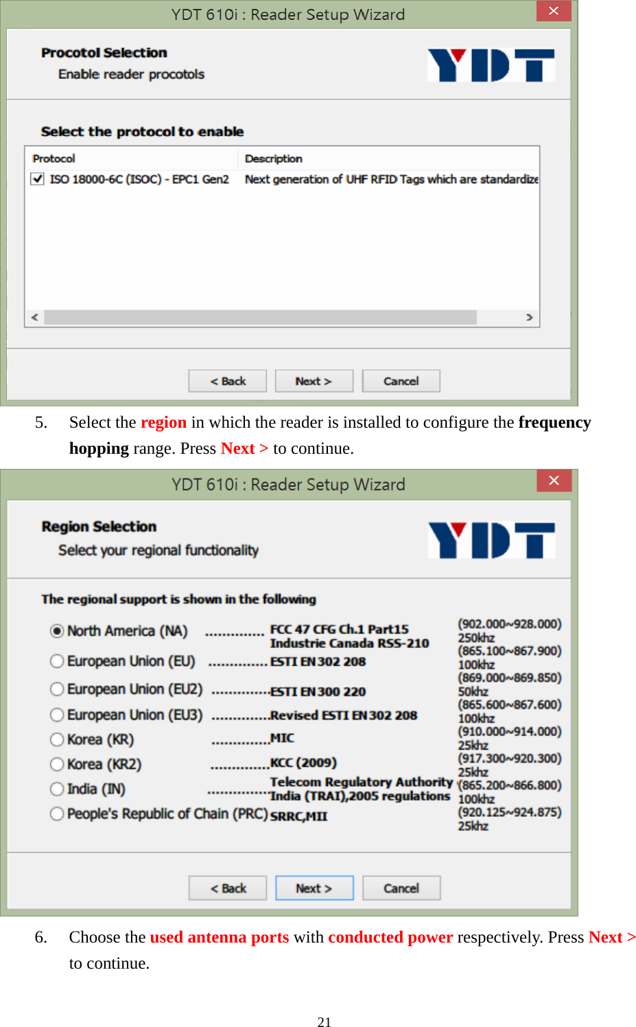
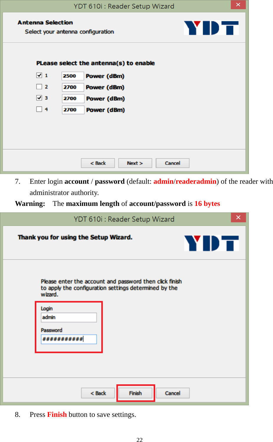
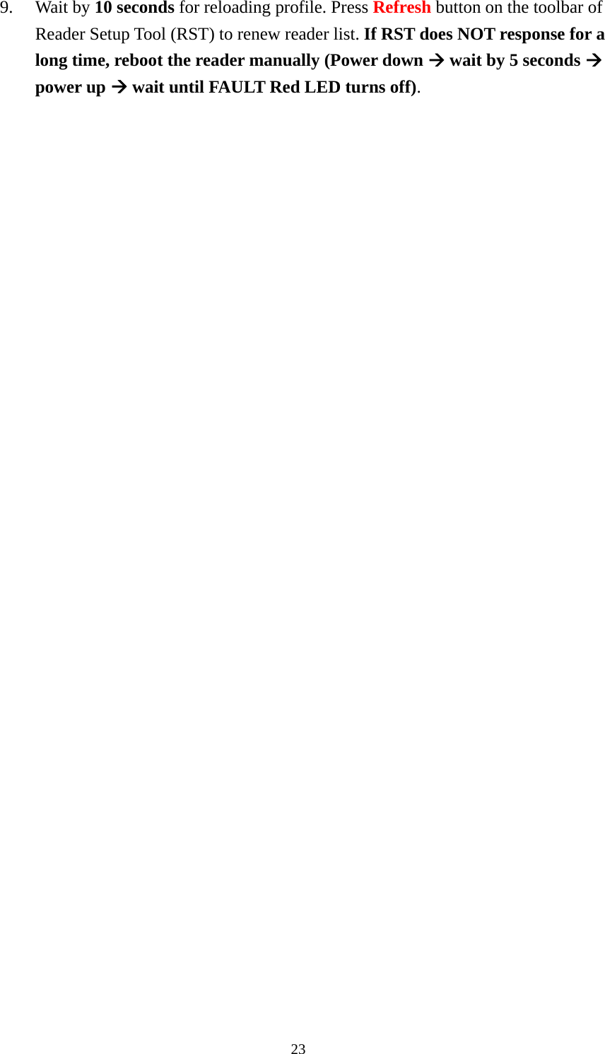
>
A800 User Manual
User Manual rev.pdf
Navigation menu
Upload a User Manual
Namespaces
Wiki Guide
HTML
PDF
Info
Views
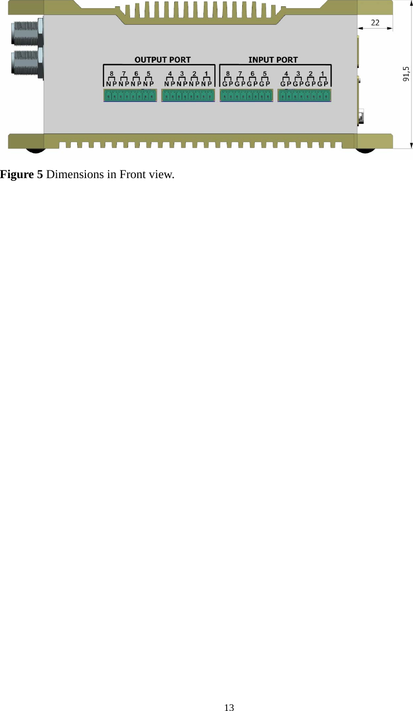
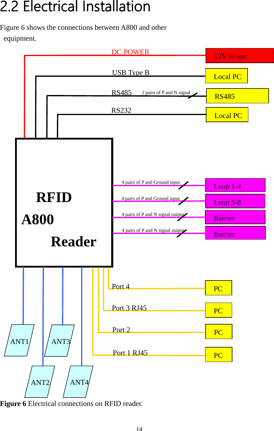
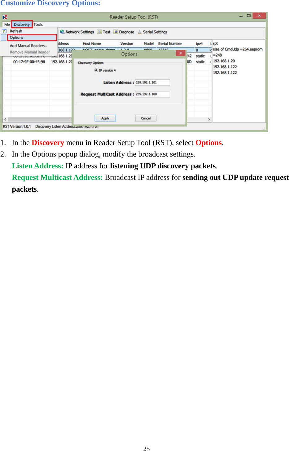
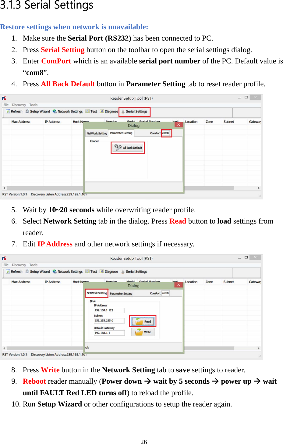
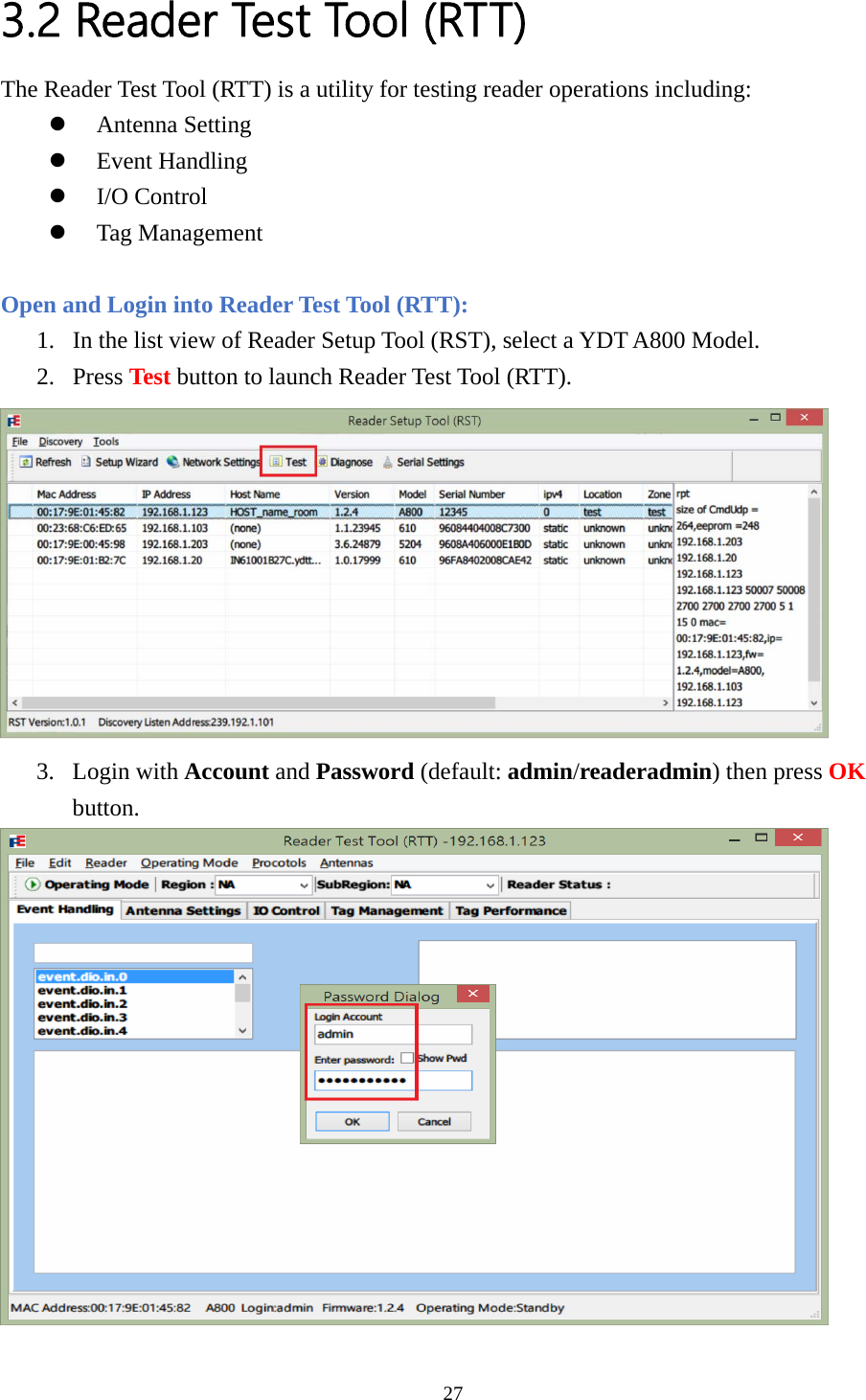
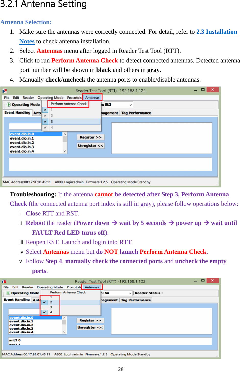
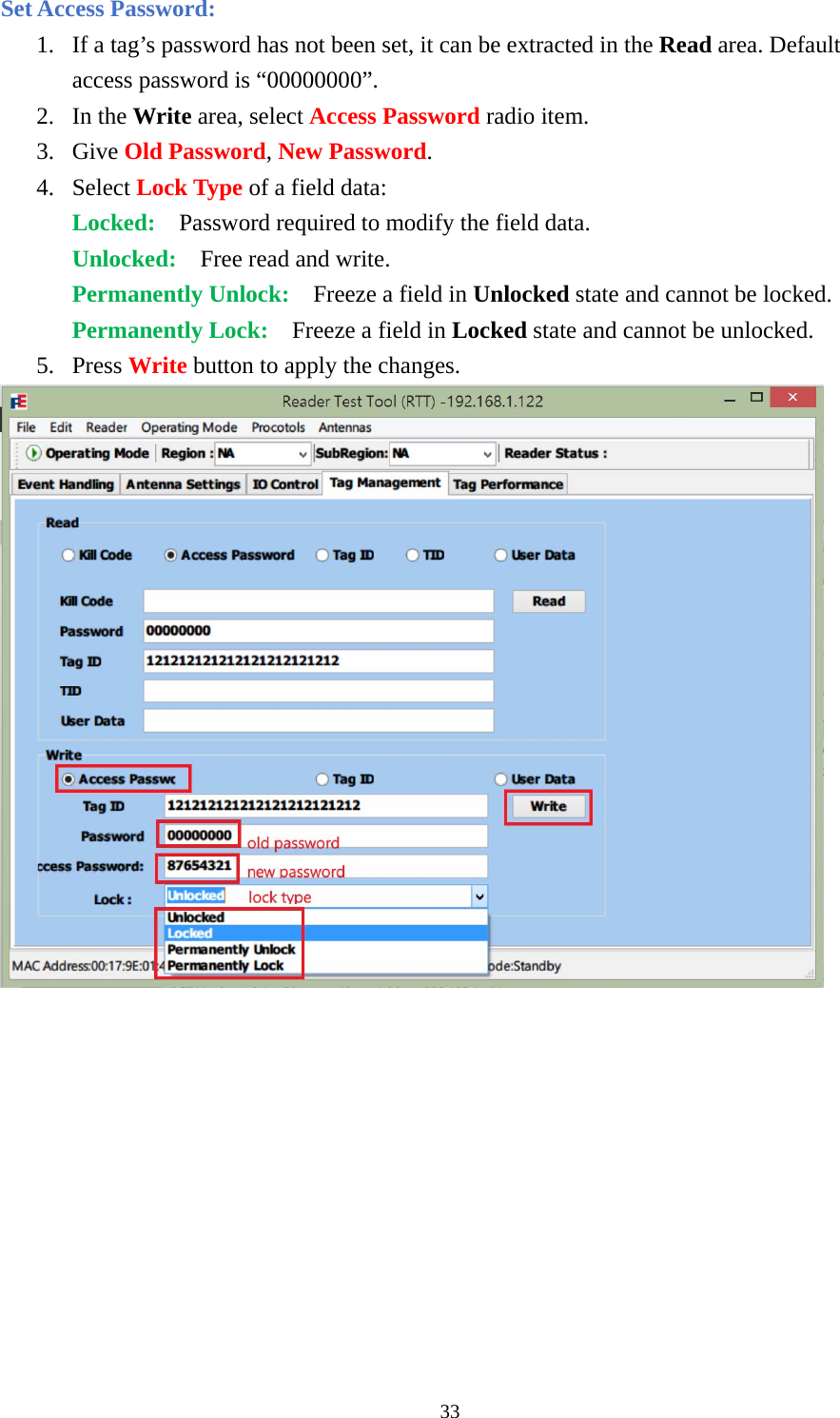
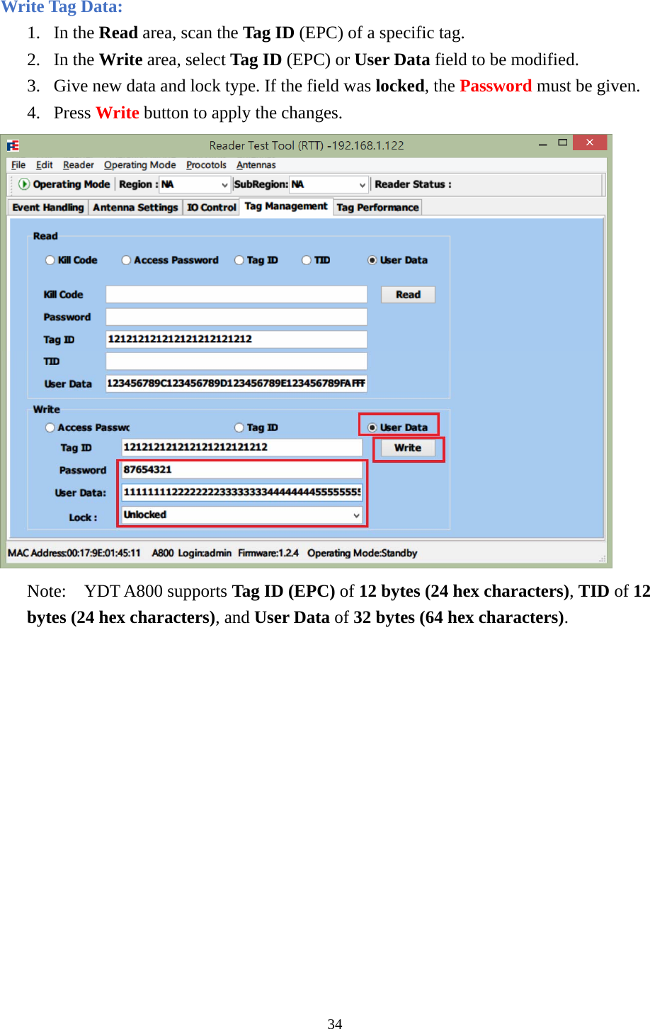
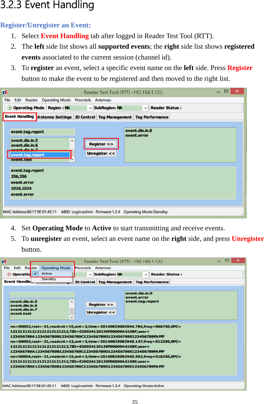
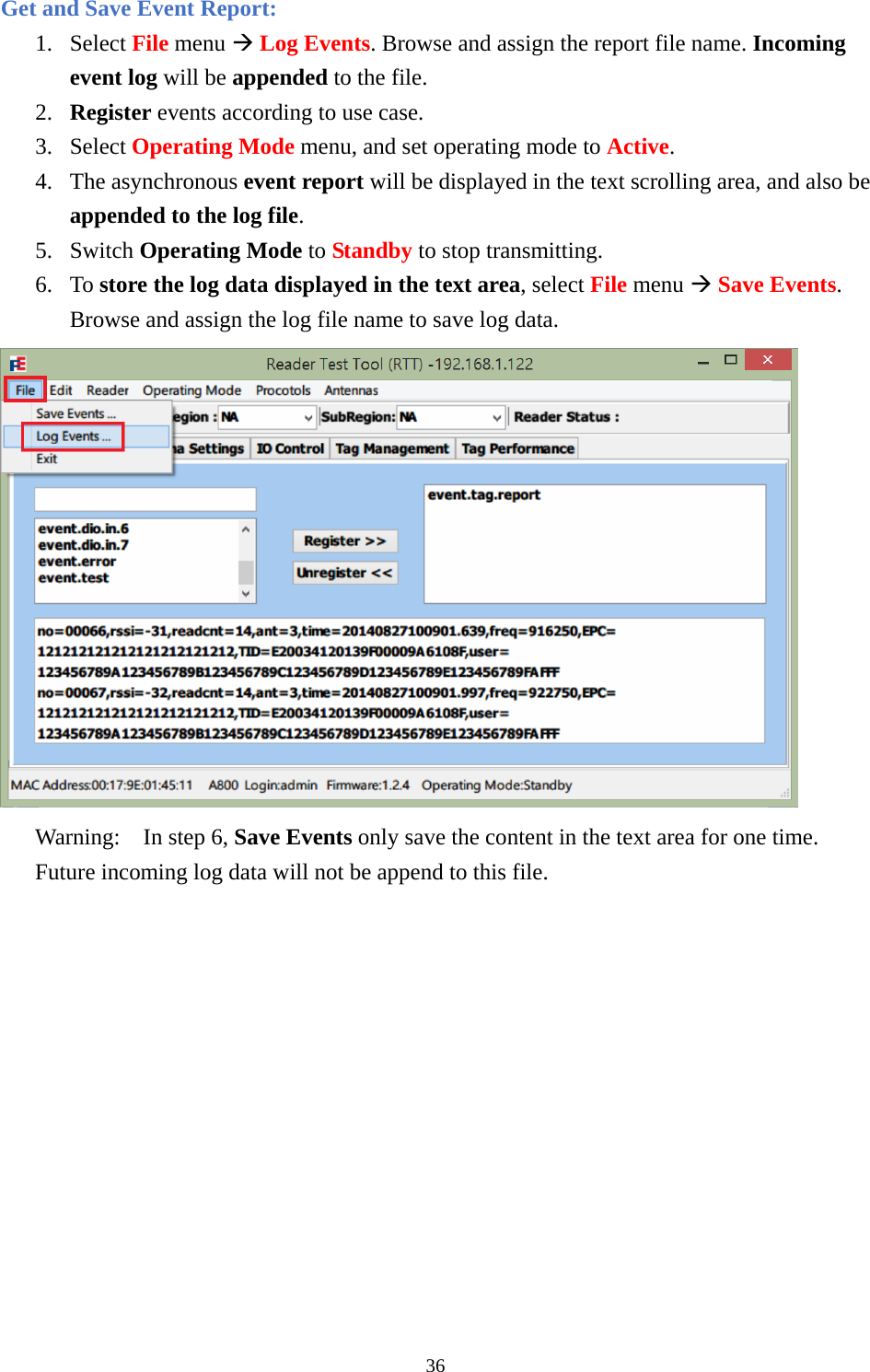
User Manual
Discussion / Help
Navigation