Yaesu Musen 03770X30 HF/VHF/UHF TRANSCEIVER User Manual Operating Manual 2
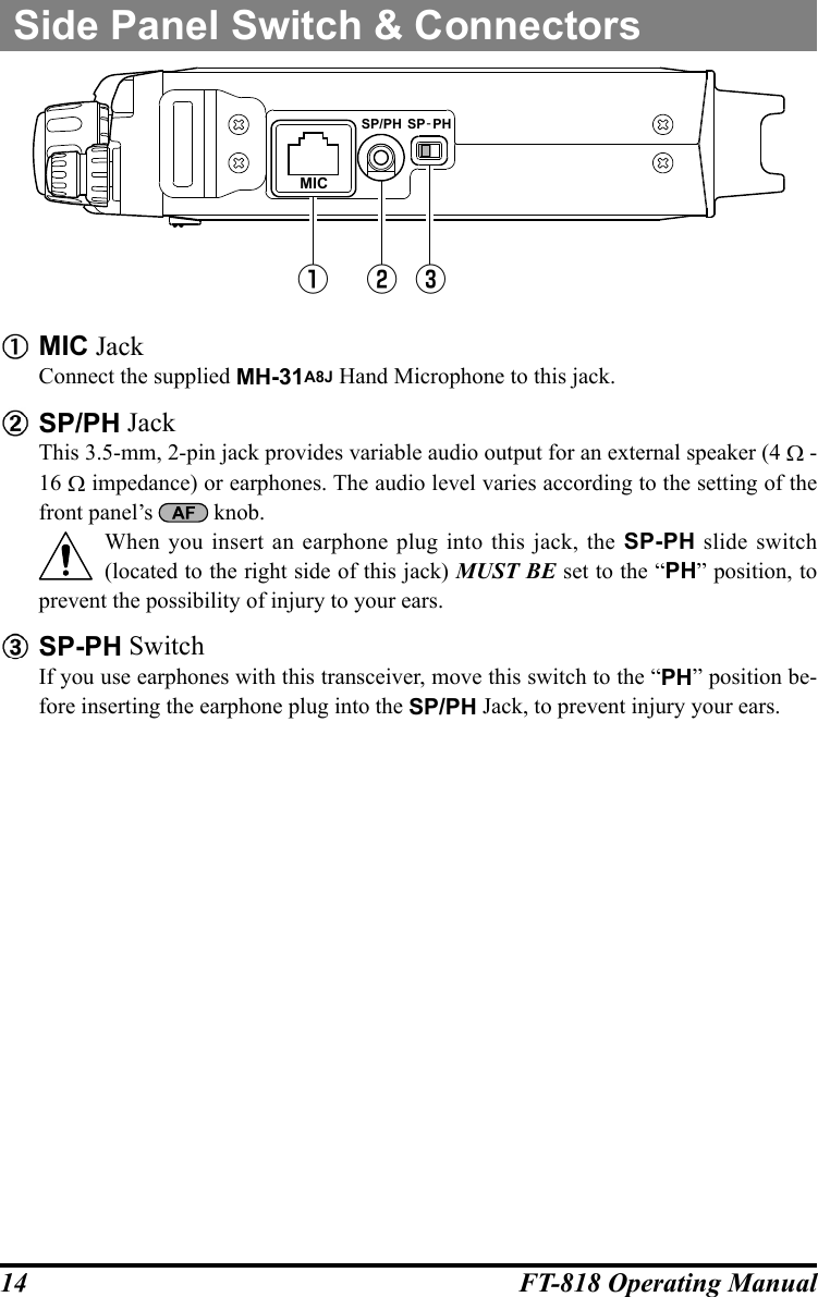
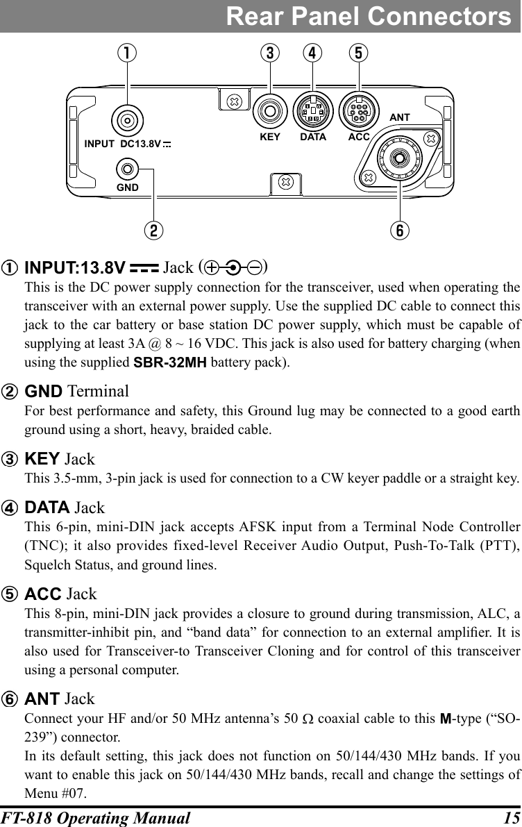
Yaesu Musen Co., Ltd. HF/VHF/UHF TRANSCEIVER Operating Manual 2
UserManual.wiki
>
Yaesu Musen
>
03770X30 User Manual
>
Operating Manual-2
Contents
1.
Operating Manual-1
2.
Operating Manual-2
3.
Operating Manual-3
4.
Operating Manual-4
5.
Operating Manual-5
6.
Operating Manual-6
Operating Manual-2
Navigation menu
Upload a User Manual
Namespaces
Wiki Guide
HTML
PDF
Info
Views
User Manual
Discussion / Help
Navigation
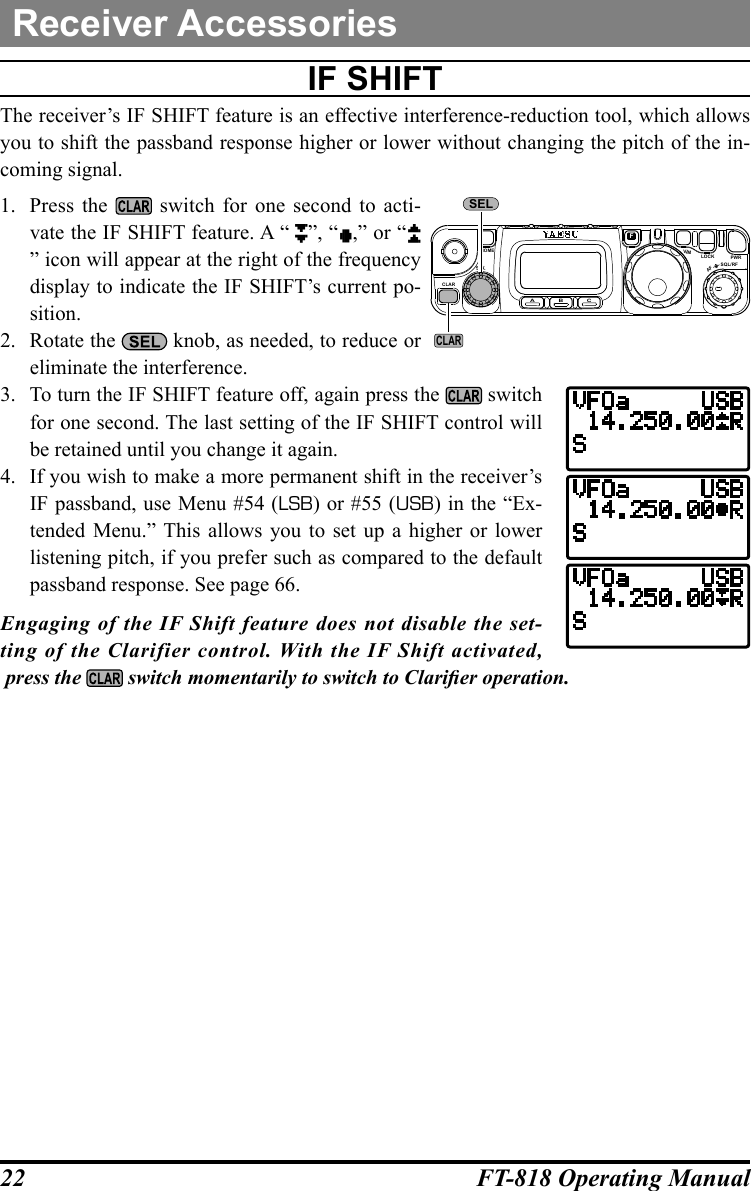
![16 FT-818 Operating Manualturning the tranSceiver On and OFF1. To turn the transceiver on, press and hold in the switch for one second.2. To turn the transceiver off, again press and hold in the switch for one second.The one-second delay helps you avoid accidental switching on (or off) of DC power.SupplY vOltage diSplaYWhen you turn on the transceiver, the DC supply voltage is indi-cated in the upper right corner of the LCD for two seconds. After this interval, the display will resume its normal indication of the operating mode (VFOa, VFOb, or Memory Channel Number). To view the supply voltage at any time during operation:1. Press the key momentarily, then rotate the knob to select Operating Function Row 11* [CHG, VLT, DSP] on the display.2. Press the (VLT) key momentarily to display the supply voltage in the upper right corner of the LCD.3. To cancel the supply voltage display, again press the (VLT) key.Remember, the Operating Row Number does not appear on the display.If you have not operated your FT-818 within the past week, we recommend that you plug in the Battery Charger, and perform a 10 hour (use for PA-48B/C/U) charge cycle, to ensure that the SBR-32MH is ready for operation when you are.CLARELSA B CFVLOCK PWRSQL/RFAFHOMEMPWROperation](https://usermanual.wiki/Yaesu-Musen/03770X30.Operating-Manual-2/User-Guide-3744314-Page-3.png)
![19FT-818 Operating ManualOperationSetting the Operating FreQuencY1. In the “SSB/CW/DIG” modes, rotate the knob to set the frequency. Clockwise rotation of the knob increases the oper-ating frequency.2. In the “AM/FM/PKT” modes, rotate the knob to set the frequency. Clockwise rotation of the knob increases the operat-ing frequency.3. You may also use the knob to adjust the operating frequency in the “SSB/CW/DIG” modes. The knob provides faster tuning, ideal for making quick changes in frequency when you want to move across the band in a hurry. You can then use the knob to make ne frequency adjustments.4. If you press the knob momentarily, then rotate the knob, you can now change the operating frequency in 1 MHz steps, allowing very quick frequency excur-sions. This can be particularly helpful on the VHF and UHF bands.5. In step 2 above, it was mentioned that tuning in the “AM/FM/PKT” modes is accom-plished using the knob. By default, the knob is disabled in these modes; if you wish to enable the knob in these modes, use Menu #04; see page 58.6. The synthesizer steps for the knob may be adjusted independently by mode. Use Menu #06 for AM, #30 for FM, and #47 for SSB/CW/Digital. See pages 58, 62, and 65 for details.The main knob synthesizer’s tuning rate (the number of steps per rotation of the knob) can be adjusted using Menu #33. See page 63 for details. Stacked vFO SYSteM1. Press the key momentarily, then rotate the knob, as needed, until Operating Function Row 1 [A/B, A=B, SPL] appears on the display.2. Now press the (A/B) key to toggle between the “A” and “B” VFOs. There are two such VFOs provided on each Amateur band, so you may set VFO-A to the CW sub-band, and VFO-B to the SSB sub-band, if you like. The operating mode will be preserved, along with the frequency information, on each VFO.CLARELSA B CFVLOCK PWRSQL/RFAFHOMEMSEL DIAL](https://usermanual.wiki/Yaesu-Musen/03770X30.Operating-Manual-2/User-Guide-3744314-Page-6.png)
![20 FT-818 Operating ManualOperationOperatiOn On 5 Mhz band (u.S. verSiOn OnlY)The FT-818 includes the capability for transmission and reception on the ve spot frequen-cies assigned to the Amateur Service in the United States. To operate on the 5 MHz band:1. Press the key once to enter the “Memory” mode (a memory channel number “M-nnn” will appear on the display in the space previ-ously occupied by “VFOa” or “VFOb”).2. Rotate the knob to select the desired channel (“M-601” through “M-605”), at the factory, with the permitted frequencies in the 5 MHz band. If you have partitioned your memory channels into Memory Groups via Menu #34, the memory channel numbers for 60-meter operation will be displayed as “l - 001” ~ “l-005.” See page 44 for details regarding Memory Group opera-tion, and page 63 for details regarding Menu #34.3. Pressing the or key momentarily, switches the operating mode between SSB and CW.4. To exit from 60-meter operatin and return to the VFO mode, just press the key (the memory channel number will be replaced by “VFOa” or “VFOb”).The frequencies and operating mode for 5 MHz band operation are both xed, and may not be changed.PSK Operation on 5 MHz Band1. Press the key once, if necessary, to enter the “Memory” mode.2. Rotate the knob to select the desired channel (“M-601” through “M-605”), at the factory, with the permitted frequencies in the 5 MHz band.3. Press the or key to select the SSB mode.4. When the “transmit” command is received from the TNC, the FT-818 trans-mitter will be engaged. The microphone input is disabled automatically when transmitting the PSK signal. Likewise, the TNC “receive” command will cause the radio to revert to the re-ceive mode.You can adjust DATA input level using Menu #25 [DIG MIC].During PSK operation via the rear panel DATA jack, the front panel MIC jack is cut off, so you won’t have a “live microphone” problem during data opera-tion.Set the PSK sub carrier frequency of the TNC to 1.5 kHz.Memory Group “OFF”Memory Group “ON”CH No. FrequencyM-601 5.3320 MHzM-602 5.3480 MHzM-603 5.3585 MHzM-604 5.3730 MHzM-605 5.4050 MHzCLARELSA B CFVLOCK PWRSQL/RFAFHOMEMSELV/M](https://usermanual.wiki/Yaesu-Musen/03770X30.Operating-Manual-2/User-Guide-3744314-Page-7.png)
![21FT-818 Operating ManualclariFier (receiver increMental tuning)The Clarier (RIT) allows you to set an offset of up to ±9.99 kHz of the receive frequen-cy relative to your transmit frequency. To achieve a wider offset than this, you may use the “Split” operating mode, described later.1. Press the switch momentarily to activate the Clarier function.2. Turn the knob, which allows the receiver frequency to be varied over a range of 9.99 kHz.3. When the receiving frequency is higher than transmit frequency, the “ ” icon will appear at the right of the frequency display. Similarly, when the receiving frequen-cy is lower than transmit frequency, the “ ” icon will appear at the right of the frequency display.4. When the receiving frequency is equal to transmit frequency (Clarier offset is zero) while the Clarier is activated, the “” icon will appear at the right of the frequency display.5. To turn the Clarier off, again press the switch momen-tarily. When you turn the Clarier back on, the offset previ-ously stored will still be applied.6. To reset the Clarier offset to zero, turn the Clarier off, then turn the knob by any amount. The Clarier will reset to zero after the rst “step” of the knob. If you leave the Clarier on, moving the knob will not cause the offset to be can-celled.CLARELSA B CFVLOCK PWRSQL/RFAFHOMEMSELCLAR[TX < RX][TX > RX][TX = RX]Receiver Accessories](https://usermanual.wiki/Yaesu-Musen/03770X30.Operating-Manual-2/User-Guide-3744314-Page-8.png)
![23FT-818 Operating ManualReceiver Accessoriesagc (autOMatic gain cOntrOl)The receiver recovery time constant of the AGC system may be modied to match your operating needs.1. Press the key momentarily, then rotate the knob, as needed, until Operating Function Row 8 [NB, AGC] appears on the display.2. Press the (AGC) key to toggle the AGC recovery time constant among the follow-ing selections: “AGCauto” “AGCfast” “AGCslow” “AGCoff” “AGCauto” …… where “AGCauto” represents “AGCfast” on CW and DIG(AFSK), and “AGCslow” on the voice modes.If “AGCoff” selected, the S-meter (which monitors AGC voltage) will cease to function.nOiSe blankerThe IF Noise Blanker may be useful in reducing or eliminating some types of impulse noise, especially noise generated by automotive ignition systems.1. Press the key momentarily, then rotate the knob, as needed, until Operating Function Row 8 [NB, AGC] appears on the display.2. Press the (NB) key to activate the Noise Blanker. The “” icon will appear at the right of the “NB” indication.3. Press the (NB) key again to turn the Noise Blanker off.ipO (intercept pOint OptiMizatiOn)The IPO feature bypasses the receiver RF preamplier, thereby eliminating the preamp’s gain. This feature is not available on the 144 MHz and 430 MHz.1. Press the key momentarily, then rotate the knob, as needed, until Operating Function Row 7 [IPO, ATT, NAR] appears on the display.2. Press the (IPO) key to bypass the receiver input preamplier. The “” icon will appear at the right of the “IPO” indication.3. Press the (IPO) key once more to re-activate the preamp.On the bands below 14 MHz, the input preamplier is rarely necessary, and activation of the IPO feature will provide substantial protection against intermodulation and oth-er problems associated with strong signal input to the receiver. Rule of thumb: so long as the S-meter is moving on background noise, additional front-end gain is not neces-sary.](https://usermanual.wiki/Yaesu-Musen/03770X30.Operating-Manual-2/User-Guide-3744314-Page-10.png)