Yoko Technology RYKIP2280 Wireless Consumer IP P/T Camera User Manual MU IP2280 eng 20080716
Yoko Technology Corp Wireless Consumer IP P/T Camera MU IP2280 eng 20080716
UserManual.wiki
>
Yoko Technology
>
RYKIP2280 User Manual
User manual
Navigation menu
Upload a User Manual
Namespaces
Wiki Guide
HTML
PDF
Info
Views
User Manual
Discussion / Help
Navigation
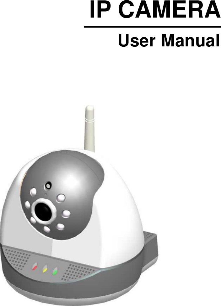
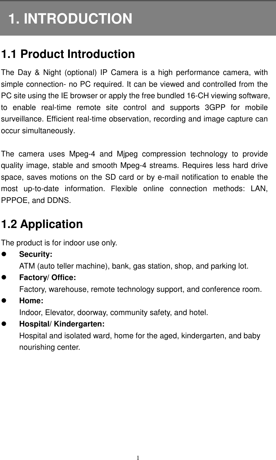
![14Then a window will appear asking you to confirm whether or not you want to install the ActiveX control. Select “Install” and the installation will take care of itself. If you are unable to install ActiveX Control, please try again following the procedures below: 1. On the IE browser Menu item bar, select [Tools] [Internet Options] item. Tools Internet Options 2. Select [Security] [Internet] and then click [Custom Level]. Security Internet Options Custom Level](https://usermanual.wiki/Yoko-Technology/RYKIP2280/User-Guide-1011065-Page-18.png)
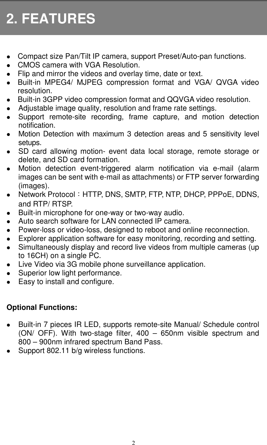
![153. After clicking on [Custom Level …] button, a security settings window appears. Please follow the steps below to change items to “Enable” or “Prompt”. Download unsigned ActiveX controls: [Prompt] Download signed ActiveX controls: [Prompt] Automatic prompting for ActiveX controls: [Enable] Initialize and script ActiveX controls not marked as safe: [Enable] Run ActiveX control and plug-ins: [Prompt] Script ActiveX controls marked safe for scripting: [Enable] Activate ActiveX Control 4. Select [Security] [Trusted sites] and then click [Custom Level].](https://usermanual.wiki/Yoko-Technology/RYKIP2280/User-Guide-1011065-Page-19.png)
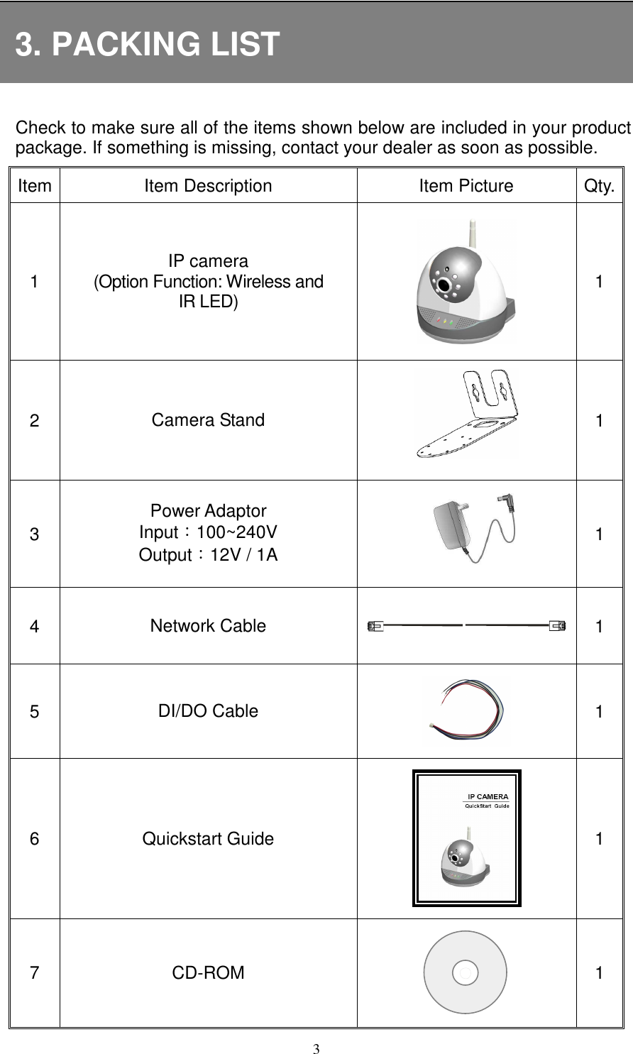
![165. After clicking on [Customer Level…] button, a security settings window appears. Please follow the steps below to change items to “Enable” or “Prompt”. Download unsigned ActiveX controls: [Prompt] Initialize and script ActiveX controls not marked as safe: [Prompt] Download ActiveX Control](https://usermanual.wiki/Yoko-Technology/RYKIP2280/User-Guide-1011065-Page-20.png)
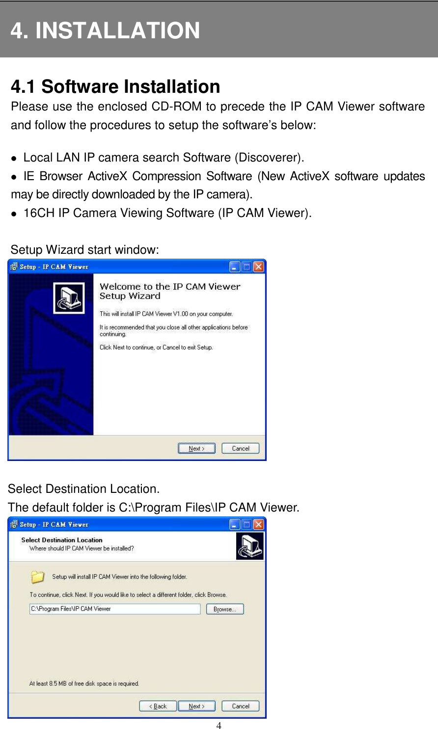
![20Click the last item “Display Title Bar”. The title bar will be displayed across the top of the screen display, as shown below: Motion Detection Inactivated Motion Detection Activated Stop Recording Recording Camera Unconnected Camera Connected Camera Name IP Address Image Resolution Frames per Second Bite Rate Display Percentage Note: Click [Setup] during recording or exiting LIVE page, a message pops up “The recording is still working. If you want to stop, please press “OK” button, or you can press “cancel” button to keep recording”. This means you may click [OK] to stop current recording or click [Cancel] to remain on the current page and continue recording. NOTE: Due to the layout of the “Display Title Bar” display, Live image display looks as if it is pushed downward and partly cut off.](https://usermanual.wiki/Yoko-Technology/RYKIP2280/User-Guide-1011065-Page-24.png)
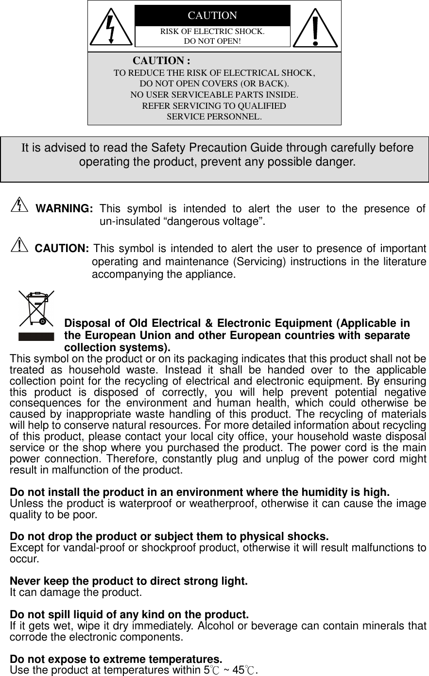
![217.2 Date/ Time Settings 1 Time Zone:Select the local time zone. 2 Setup Date / Time via Network Time Protocol (NTP):Synchronize date/ time with the time server. NTP Server:Enter the IP address or domain name of the time-server. 3 Manual Setup Date / Time: Date:Select Date. Time:Select Time. 4 Get Current Date/ Time from the PC:Synchronize date/ time through user PC. Click to synchronize date/ time with the PC. Click [Apply] button to complete the setup.](https://usermanual.wiki/Yoko-Technology/RYKIP2280/User-Guide-1011065-Page-25.png)
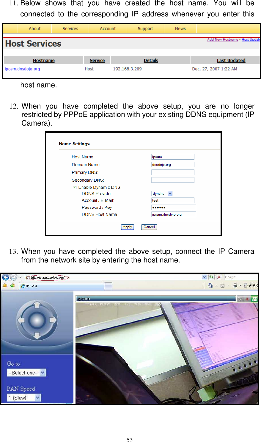
![227.3 Name Settings 1. Host Name:Enter IP CAM host name. Tip :Applicable alphanumeric characters :Underline (_), hyphen (-), numbers (0 - 9) and alphabet (a - z, A - Z). 2. Domain Name:Enter domain name (optional field, administrator login only)。 3. Primary DNS:Enter IP address for DNS1 (required field, for example 168.95.1.1). 4. Secondary DNS:Enter IP address for DNS2(optional field, used as reserved DNS name). 5. Enable Dynamic DNS:Select to enable DDNS, but first register an account with the dynamic DNS service (optional field, relevant only to IP CAM using dynamic IP address). DDNS Provider:Select websites that provides Dynamic DNS services that lets you gain access to monitor your IP CAM on a local network when the internet address of that network is constantly changing. Suggested Dynamic DNS service provider: dhs, dyndns, dyns, easydns, gnudip, justlinux, ods, pgpow, and tzo (please refer to 11 APPENDIX for detailed information). Account / E-Mail:Enter Account or E-mail field for logging in the DDNS server or notify the user of the new IP address. Password / Key:Enter the password or key to get the DDNS service. DDNS Host Name:The field is created automatically when the Host Name and the Domain Name that is registered in the DDNS serer has been entered. Click [Apply] button to complete the setup.](https://usermanual.wiki/Yoko-Technology/RYKIP2280/User-Guide-1011065-Page-26.png)
![237.4 IP Settings 1 IP Settings: (1) Setup Dynamic IP (DHCP):Assign an IP address via DHCP server. Enable DHCP to allow centralized assignation of IP addresses. (2) Setup Static IP:Setup fixed IP address manually. IP Address:Enter fixed IP address. Subnet Mask:Enter subnet mask. Gateway:Enter network gateway. (3) Setup IP via PPPOE: User Name:Enter user account(provided by the Internet Service Provider). Password :Enter password (provided by the Internet Service Provider). (4) Wireless Interface IP Settings: Take wireless interface as backup device :Wireless network connection method is applied when cable network connection failure occurs. Disable wireless interface:Wireless network connection method will not be applied when cable network connection failure occurs. Click [Apply] button to complete the setup.](https://usermanual.wiki/Yoko-Technology/RYKIP2280/User-Guide-1011065-Page-27.png)
![247.5 Wireless Network Settings 1 Communication Mode:Setup communication mode (Infrastructure or Ad-Hoc, normally apply Infrastructure). 2 Wireless Network Name (SSID):Setup wireless network name. 3 Wi-Fi Channel number:Setup channel (Auto, 1~11) 4 Wireless Mode:Select wireless mode (11B/11G mixed mode, 11G only, or 11B only. 5 Wireless Encryption:Select wireless encryption mode (Disable/ WEP). (1) Disabled (Open system):Disable wireless encryption mode. (2) WEP (Shared Key):Select shared key. WEP Mode:Select 64-bit or 128-bit, normally apply 64-bit. Default Key ID:Select shared key (1~ 4). Key Entry Method:Select enter method [ASCII (5 characters) or Hex (10 digits)], normally apply ASCII. Key 1~4:Setup maximum of 4 shared keys.](https://usermanual.wiki/Yoko-Technology/RYKIP2280/User-Guide-1011065-Page-28.png)
![25(3) WPA-PSK WPA Encryption:Select TKIP or AES. Pre-shared Key Type:Select shared key type [Passphrase (8-63 characters) or Hex (64 digits)]. Pre-shared Key:Enter password. Click [Apply] button to complete the setup. Note: When “Setup Dynamic IP (DHCP)” is set under IP Settings page and “Ad-Hoc” is set under Wireless Communication Mode, a message pops-up “When DHCP mode is enabled, Communication Mode can’t be set as “Ad-Hoc””.](https://usermanual.wiki/Yoko-Technology/RYKIP2280/User-Guide-1011065-Page-29.png)
![267.6 Video Settings 1 Video Property Settings:Setup video property. Brightness, Contrast, Saturation, Hue adjustment (Setup Range: 0 - 255) Flip:Flip image (up/ down, Setup Range: 0 - 255). Mirror:Mirror image (left/ right, Setup Range: 0 - 255). OSD Timer:Display OSD timer (Setup Range: 0 - 255). Flip:Flips an image upside. Mirror:Reverses image left and right. OSD Timer:Reveal time on OSD display. Out/In Door:Select outdoor when camera is installed outdoor to avoid overexposure. And use indoor camera if it is installed indoor, please setup using fluorescent lights 60/ 50 Hz (Default: 60 Hz). NOTE:To store applied setup within your IP Cam, please make sure to click [Apply] button.](https://usermanual.wiki/Yoko-Technology/RYKIP2280/User-Guide-1011065-Page-30.png)
![27 2 Video Stream Mpeg4 (Mpeg4 stream settings) (1) Streaming Property Setting: Frame Rate:Select fps [5, 10, 15, 20, 25FPS]. Resolution:Select resolution [QVGA (320 x 240) or VGA (640 x 480)]. (2) Streaming Bit Rate Control:Select streaming bit rate. Constant Bit Rate:Depends on Bit Rate [16K bps~3M bps]. Constant Quality:Depend on quality [OK, Medium, Standard, Good, or Great]. 3 Video Stream MJpeg (MJpeg stream settings) (1) Streaming Property Setting: Frame Rate:Select fps [5, 10, 15, 20 or 25]. Resolution:Select resolution [QVGA (320 x 240) or VGA (640 x 480)]. (2) Streaming Bit Rate Control:Select streaming bit rate. Constant Bit Rate:Bit Rate value is fixed, 16K bps - 3M bps Constant Quality:Depend on quality [OK, Medium, Standard, Good, or Great]. Please refer to “7.15 System Settings” before 3GPP setup. NOTE:Two types of video stream: MPEG-4 and MJPEG (total of 30 FPS). MPEG-4 (default) provides 25FPS, while MJPEG provides only 5FPS. User can adjust the frame rate size according to preference. NOTE:Due to 5FPS is auto provided ones 3GPP function has been activated. Therefore, the video frame rate for MPEG-4 video stream is decreased to 25FPS.](https://usermanual.wiki/Yoko-Technology/RYKIP2280/User-Guide-1011065-Page-31.png)
![28 4 Video Stream 3GPP (1) Streaming Property Setting: Frame Rate:Select 5fps. Resolution:Select resolution [QQVGA (160x120)]. (2) Streaming Bit Rate Control:Select streaming bit rate. Constant Bit Rate:Bit Rate value is fixed, 16K bps – 64K bps Constant Quality:Depend on quality [OK, Medium, Standard, Good, or Great]. Click [Apply] button to complete the setup. A connection with low bandwidth, the system automatically reduces the Frame Rate and Bit Rate. When no users are connected, the system automatically restores the Frame Rate and Bit Rate to user setting. NOTE:Use professional software(ex: VLC)to directly receive Mjpeg data stream and to record more vivid videos. Enter rtsp://IP add/jpegmp2 to receive Mjpeg video stream rtsp://IP add/3gv2 to receive 3GPP video stream](https://usermanual.wiki/Yoko-Technology/RYKIP2280/User-Guide-1011065-Page-32.png)
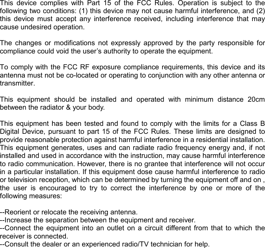
![297.7 Motion Detection Windows Motion Detection Window Settings:Use the mouse to click, hold and drag the window frame, remember to click [Apply] in order to validate the change. 1 Motion Detection Window Settings :Setup motion detection area parameters. Window 1, 2, 3:[Enable/ Disable] motion detection setup for window 1-3. Sensitivity 1, 2, 3:[Very High, High, Normal, Low, or Very Low] sensitivity rate setup for window 1-3. Click [Apply] button to complete the setup.](https://usermanual.wiki/Yoko-Technology/RYKIP2280/User-Guide-1011065-Page-33.png)
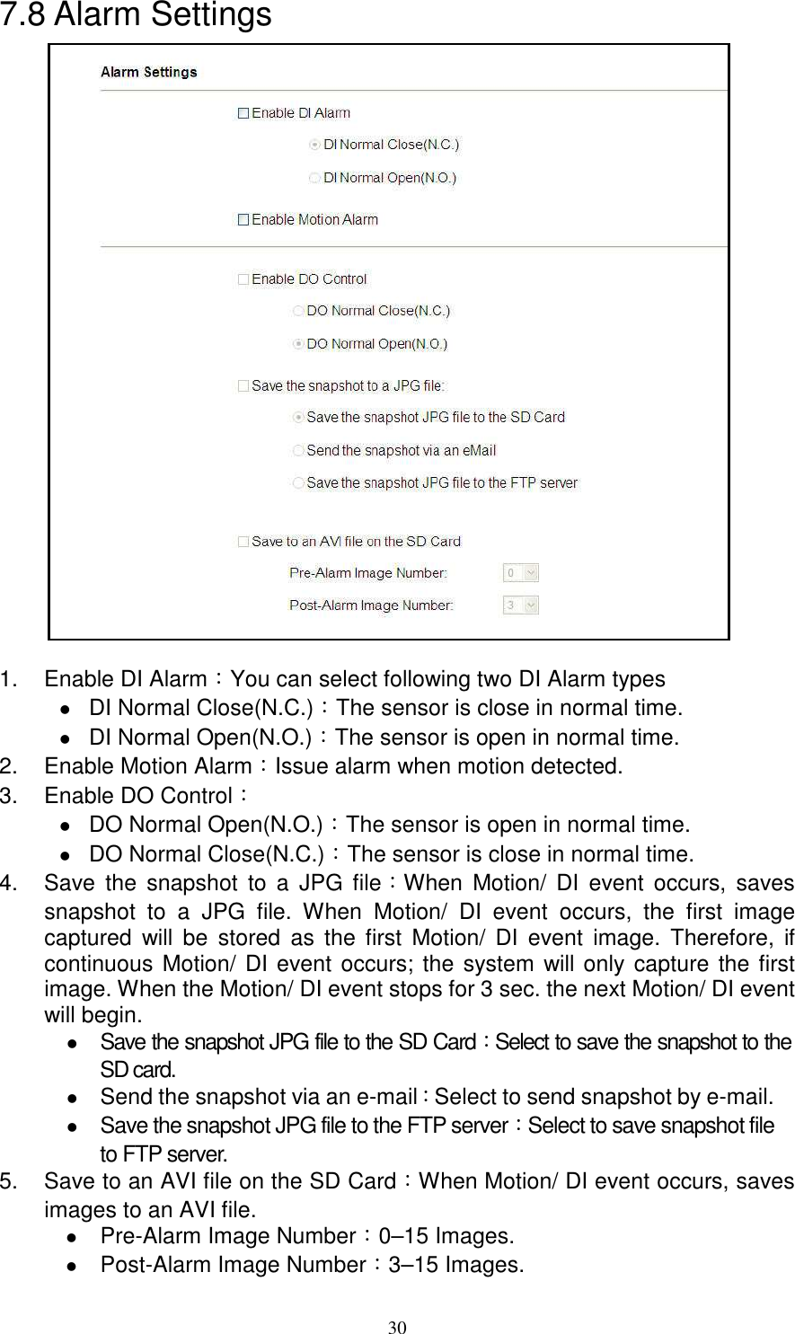
![31 6. Alarm OFF/ Alarm On/ Alarm Schedule When you select the Alarm Schedule, the above alarm settings will be triggered only within the scheduled timeline. Move the cursor to any white grid area, hold the left button and move the cursor to draw the grid from white to blue (each grid represents half an hour). Click [Apply] button to complete the setup. Note: Select either one of the function [Save the motion snapshot to a JPG file] or [Save motions to an AVI file on the SD Card], but not both. Note: When the condition of the bandwidth is inadequate, unstable, or SMTP setup is incorrect. The system may not be able to send the motion event notification by e-mail and a message appears: “Some Motion Detection JPG files are failed to be sent via email or upload to FTP due to unstable bandwidth or wrong SMTP/FTP settings. To ensure you can receive the email or upload to FTP accurately, please make sure the quality of network or check the SMTP/FTP settings”. To ensure that user can successfully receive e-mail or upload, it is suggested that the user should determine the quality of the bandwidth and check whether SMTP/ FTP has been correctly setup.](https://usermanual.wiki/Yoko-Technology/RYKIP2280/User-Guide-1011065-Page-35.png)
![327.9 IR LED Control 1 IR LED Control IR LED OFF: Disable IR function. IR LED ON:Enable IR function. Schedule ON:Enable IR LED Schedule IR LED AUTO:Enable or Disable IR LED by IP Camera automatically. 2 Daily Schedule Select IR LED ON from time 0:00 to 24:00. One grid indicates half an hour. Move the cursor to any white grid area, hold the left button and move the cursor to draw the grid from white to blue indicates the area where the IR LED is ON. Move the cursor to any blue grid area, hold the left button and move the cursor to draw the grid from blue to white indicates the area where the IR LED is OFF. Select start and end time, from the starting time hold the left button and drag along to the selected ending time. This enables multiple grids to be selected at once. Click [Apply] button to complete the setup.](https://usermanual.wiki/Yoko-Technology/RYKIP2280/User-Guide-1011065-Page-36.png)
![337.10 SD Card File Management 1 SD Card status: Indicates SD card current storage status. 2 File list:Insert the SD card to the IP camera to display file list stored in the SD card. Back:Click to return to previous folder. Select All:Select all files in the file list. Delete Select:Delete selected file in the file list. Folder in the File Size field indicates a folder. Click File Name connection to enter the relevant folder. File Size field indicates the size of the file. Click the right button to download the file. File Delete:Click [Delete] to delete file. Reload:Update current folder. 3 Safely Remove SD Card:Indicate it is safe to remove the SD card. Remove:After confirming “Save motion to AVI files on the SD card” function has been disabled. Click [Remove] button and wait for the message “SD Card not installed” to appear. Then, withdraw the SD card from the IP camera site. Thus, prevents data-damage during SD card hot swap process. Install:Clicking [Remove] button without withdrawing the SD card from the SD card slot. Enables you to click [Install] button to use the SD card again. Note:When “Save motion to AVI files on the SD card” function is enabled, “Format SD Card” function is disabled.](https://usermanual.wiki/Yoko-Technology/RYKIP2280/User-Guide-1011065-Page-37.png)
![344 Format SD Card:Click [FORMAT] button to format SD card. All recorded data in the SD card will be deleted. After format, two files “AlarmPicture and AlarmVideo” will be created and motion-event data will be stored in these two files. 5 When motion recording is activated it will be stored instantly onto the SD card. Do not attempt to open recording files during recording as error may occur and the following message will appear. To view the file immediately, uncheck “Save motions to AVI file on the SD card” under Motion Alarm page, or refresh the web page and try again later, you may also take no action at all and allow Motion Recording to continue until it stops.](https://usermanual.wiki/Yoko-Technology/RYKIP2280/User-Guide-1011065-Page-38.png)
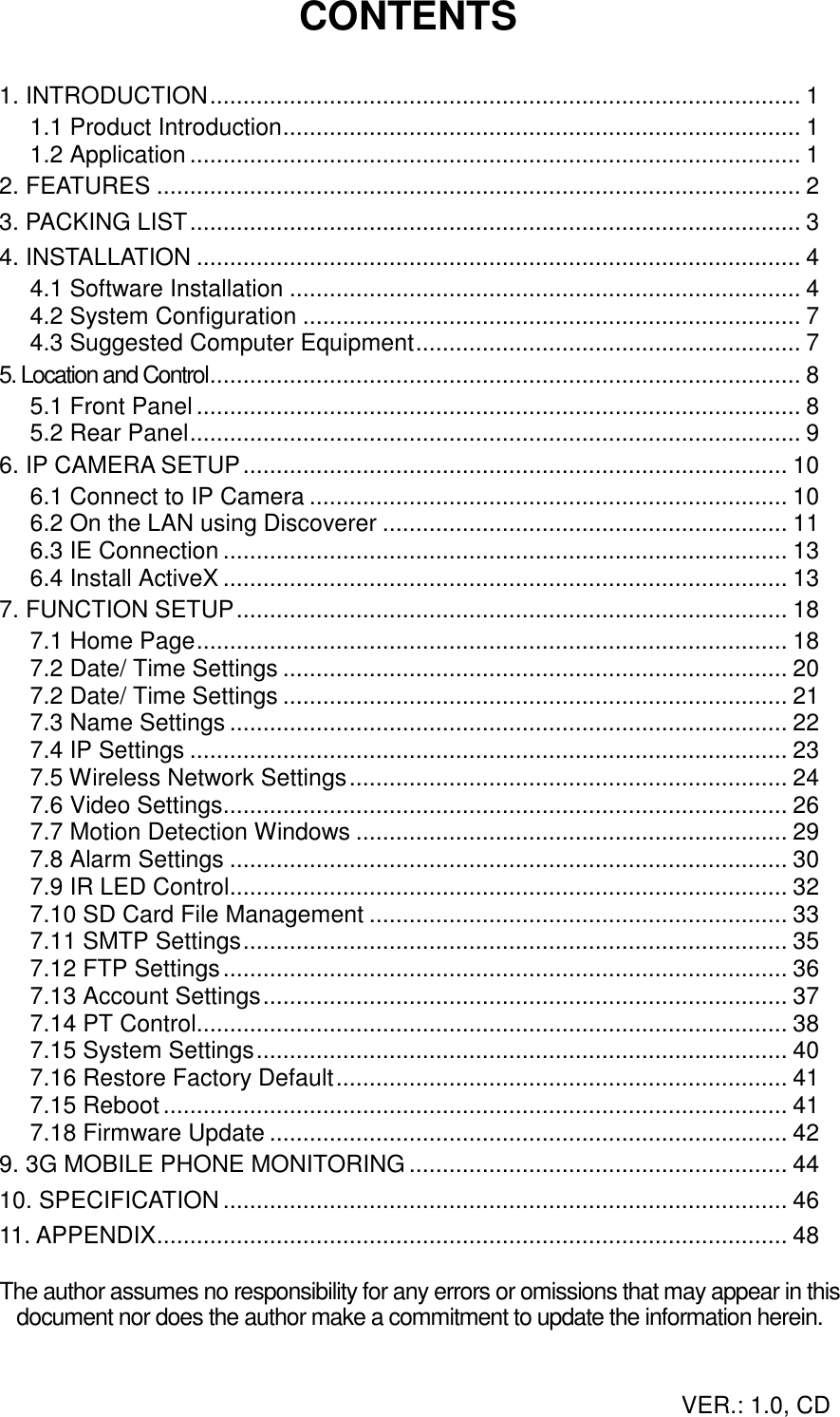
![357.11 SMTP Settings 1 SMTP Server:Setup simple mail transfer protocol to transfer mail reliably and efficiently(similar to mail function setup). 2 Recipient:Enter recipient’s e-mail address. 3 The SMTP Server need authorization:The user needs to give valid user name and password to send email via the server. Username:Enter the user name of the e-mail address. Password:Enter password. Click [Apply] button to complete the setup.](https://usermanual.wiki/Yoko-Technology/RYKIP2280/User-Guide-1011065-Page-39.png)
![367.12 FTP Settings 1 FTP Server:Enter FTP address, to enable file transfer via FTP when a Motion/ DI event occurs. 2 FTP Port:Enter FTP Port(normally apply 21). 3 Username:Enter active user name of FTP server. 4 Password:Enter FTP user password. 5 Remote Folder:Create a remote folder; it should be the same name as your relative root folder. For example, if you setup an FTP account name user1 and wants to store a jpg file to“/home/user1/FolderName/”, then you need only to enter “/FolderName”. If the file is not found on the FTP server, it is auto created. When the file is found, enable the authority of the file ($chmod 777 /home/user1/FolderName). 6 Passive Mode:Select passive mode. Click [Apply] button to complete the setup. Note:The folder is created only when a motion-event occurs.](https://usermanual.wiki/Yoko-Technology/RYKIP2280/User-Guide-1011065-Page-40.png)
![377.13 Account Settings Current User: Displays the current user. 1 Change Password New Password: Enter new password. Confirm: Enter the new password again to reconfirm. Click [Change] to validate the setup. 2 Add New Account (Maximum 32 user accounts) Account: Enter user account. Password: Enter user password. Confirm: Enter user password again to reconfirm. Click [Add] to validate the setup. 3 Delete Account or Reset User Password Select a user first. Click [Delete] to delete the user. Password: Enter new user password. Confirm: Enter new user password again to reconfirm. Click [Set Password] to validate the setup. NOTE:Account Applicable alphanumeric characters (Maximum 10units): numbers (0 - 9) and alphabet (a - z, A - Z). Password Applicable alphanumeric characters (Maximum 12units): numbers (0 - 9) and alphabet (a - z, A - Z). NOTE: Only the Admin has full control authority, the rest has view and password modification access only.](https://usermanual.wiki/Yoko-Technology/RYKIP2280/User-Guide-1011065-Page-41.png)
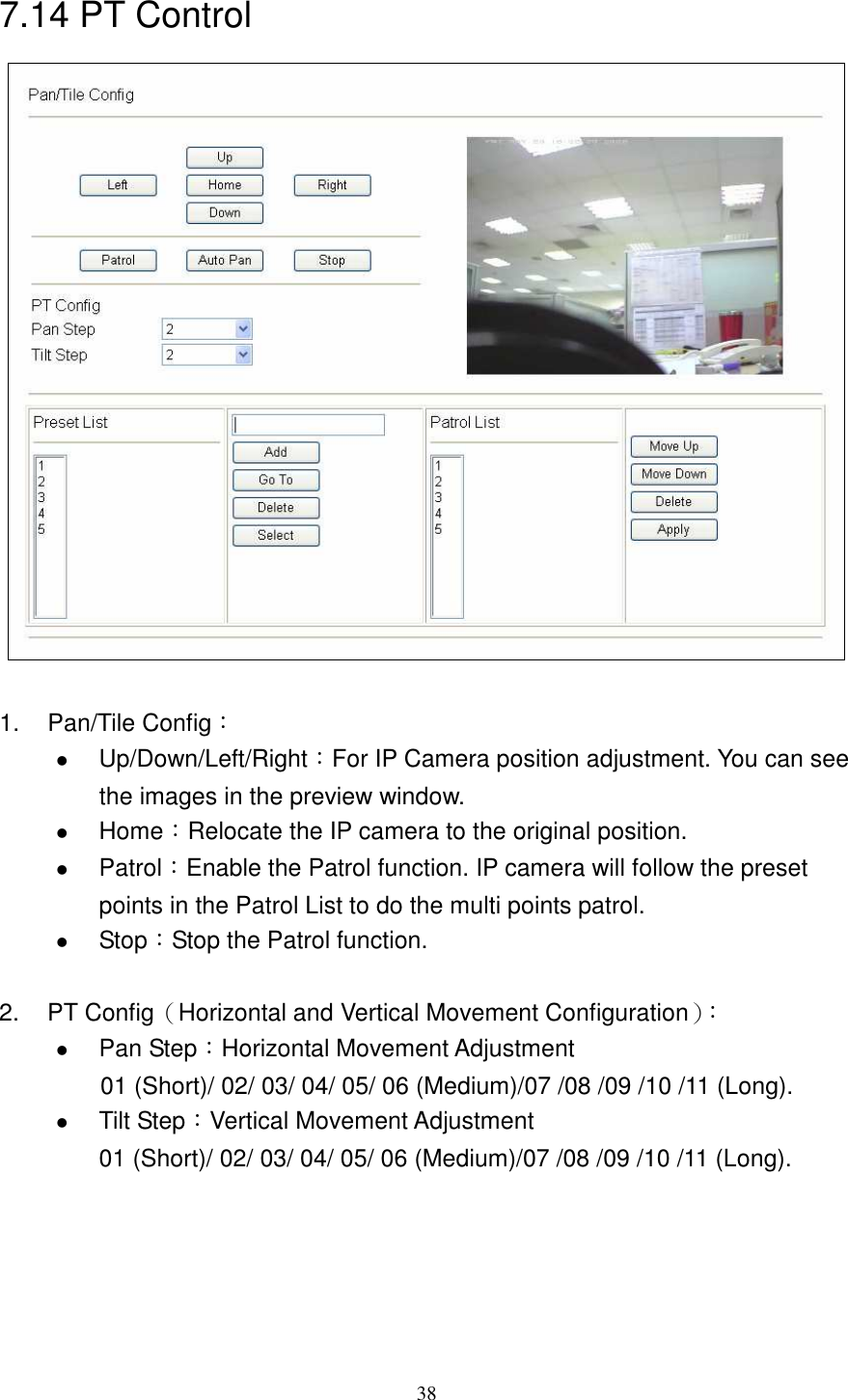
![393. Preset List:User can set the desired camera position and save it as Preset point in the Preset List. It is a preset user-defined camera position; user can move the camera position very quickly when needed. 100 preset points are allowed in the Preset List. Use the Up/Down/Left/Right buttons to adjust the camera position, and then input the preset point name in the right column of Preset List. Click “Add” button to add to Preset List. Select the desired Preset Point and then click “Go To” button, camera will move to the Preset Point position. Click “Delete” button to delete the selected Preset Point. Click “Select” button to add a selected Preset Point into Patrol List. 4. Patrol List:IP camera will follow the Preset Points in the Patrol List to do the sequential patrol (Maximum 20 Patrol List). Move Up/Move Down:To adjust the sequence of Preset Point in the Patrol List. Click “Delete” button to delete the selected Preset Point. NOTE:You have to click [Apply] button after you adding a Preset Point into the Patrol List.](https://usermanual.wiki/Yoko-Technology/RYKIP2280/User-Guide-1011065-Page-43.png)
![407.15 System Settings Image Path:The saving path of the image snapshots (*.JPG/*.AVI). The default path is C:\IPCam\. Main Video Stream:Default is Mpeg-4 (this function is read only). Second Video Stream:You can select 3GPP (Output to 3G mobile phone) or Mjpeg format. NOTE:The Profile is stored in PC and not in IP CAM. If you reinstall or renew your PC the parameter previously setup will not be stored in your new PC and the same happens when you click [Reset] button, it will not restore to factory default settings.](https://usermanual.wiki/Yoko-Technology/RYKIP2280/User-Guide-1011065-Page-44.png)
![417.16 Restore Factory Default Click [Restore] to restore the factory default settings. Any changes made so far will be lost and the system auto connects to the default IP address (Http://192.168.100.100). 7.15 Reboot Click [Reboot] and the IP camera will start rebooting. NOTE:The system can only restore factory default settings of the parameter profiles within the IP CAM, but invalid to parameter profiles store on PC.](https://usermanual.wiki/Yoko-Technology/RYKIP2280/User-Guide-1011065-Page-45.png)
![427.18 Firmware Update To install firmware updates for your IP camera. Click [Browsing] and select the firmware file named “IPCAM Firmware (bin file)”, and then click [Upgrade]. The whole process needs a few minutes, so please don’t turn off the power or press the reset button during a firmware update. Note: 1 Please confirm the connection quality and make sure that the IP camera maintains uninterrupted connection to the network. 2 When the speed of Firmware upload is very slow, please remove proxy settings first. Please follow the steps below to disable proxy server: Open IE and click [Stop] button. Click [Tools] --> [Internet Options].](https://usermanual.wiki/Yoko-Technology/RYKIP2280/User-Guide-1011065-Page-46.png)
![43 In the [Internet Options] window click the [Connections] tab. Next, click the [LAN Settings...] button. In the "Proxy Server" area, remove the check mark next to “Use a proxy server for ....”, and then click [OK] button. When firmware update failure occurs, first store the firmware file (bin file) to the SD card and then reboot the device to enable auto update. Please do not unplug the power supply or pull-out the SD card while upgrading.](https://usermanual.wiki/Yoko-Technology/RYKIP2280/User-Guide-1011065-Page-47.png)
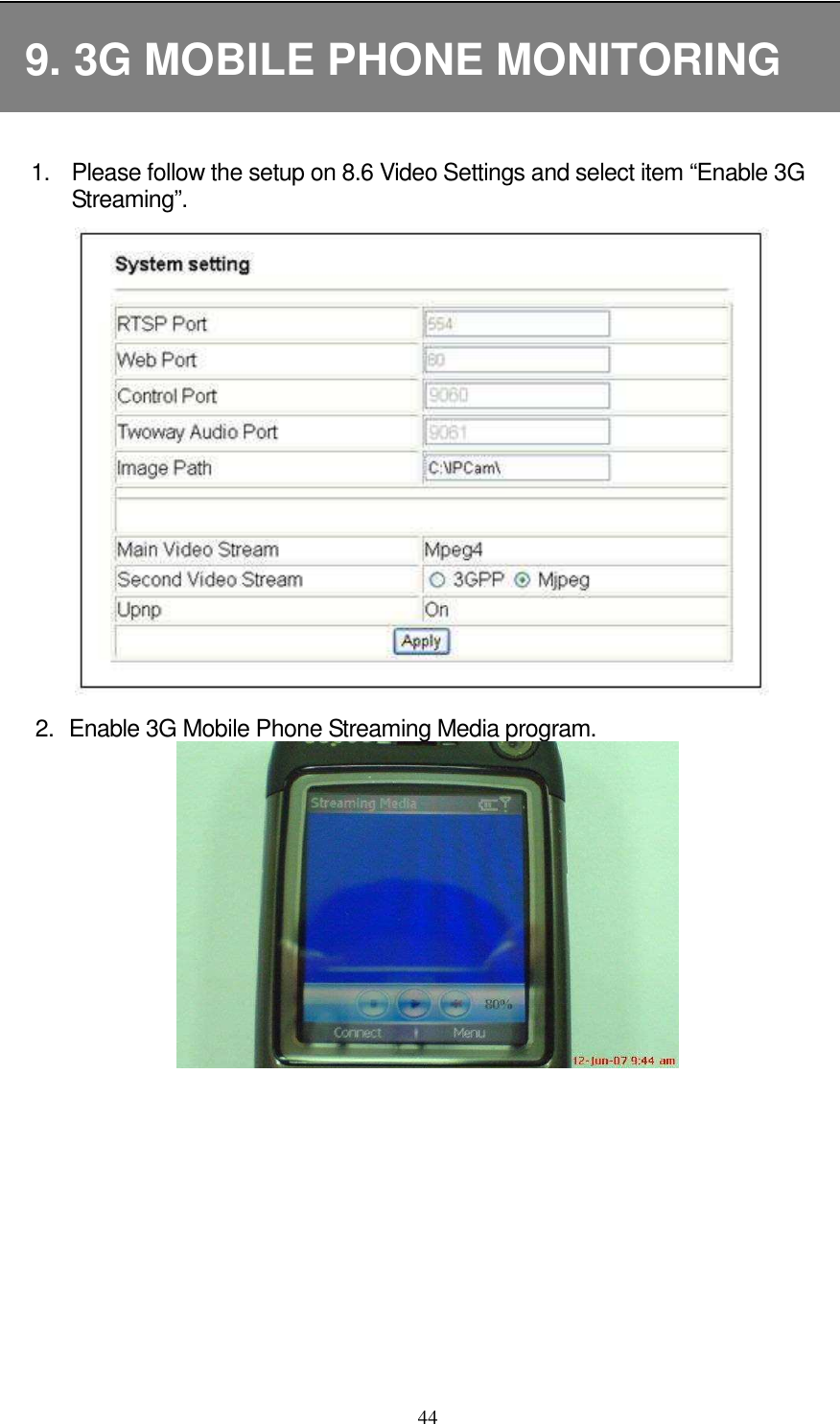
![453. Connect to the IP address of the IP camera, using URL format“rtsp://[IP address]/3gv2” (remember to add 3gv2 at the end of the IP address), as shown below: 4. When online connection is successful, image will be displayed on the mobile phone screen display. Supported cell phone brand type, listed below: Brand Nokia Motorolla Sony Ericsson Dopod Type N90 N80 N93 N95 E107 V3X K608i W900i K610i Z800i 595 CHT 9100](https://usermanual.wiki/Yoko-Technology/RYKIP2280/User-Guide-1011065-Page-49.png)
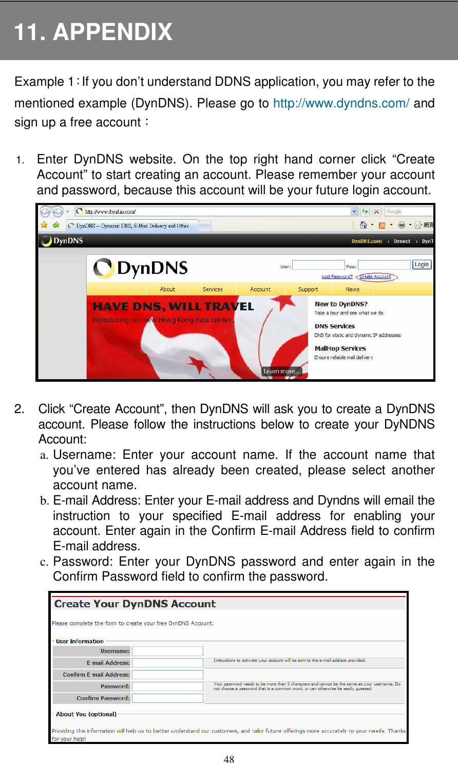
![493. Please read Acceptable Use Policy (AUP) and accept it prior to creating your account. Check “I agree to the AUP” and “I will only create one (1) free account”, and make sure the information is correct, then click [Create Account]. 4. Then, you will see the screen “Account Created”, and Dyndns will email the instructions to your specified E-mail address for enabling your account.](https://usermanual.wiki/Yoko-Technology/RYKIP2280/User-Guide-1011065-Page-53.png)
![50 5. Press the link in the mail and you will see “Account Confirmed”. Your account is created successfully now and then login with your account 6. Please return to DynDNS website. On the top right hand corner enter the “User” and “Pass” field that you just created. Then click [Login] to enter.](https://usermanual.wiki/Yoko-Technology/RYKIP2280/User-Guide-1011065-Page-54.png)