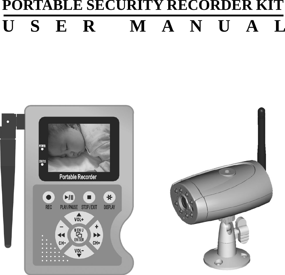
Yoko Technology YK9120K 2.4GHz wireless CCD Camera & Portable DVR User Manual

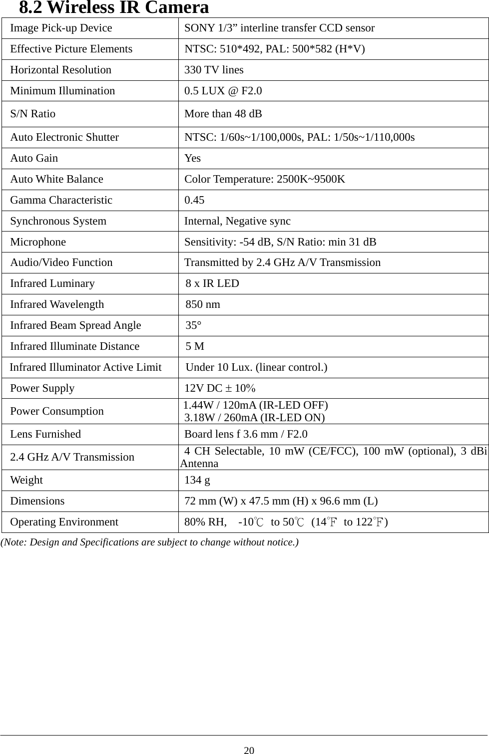
Yoko Technology Corp 2.4GHz wireless CCD Camera & Portable DVR

Users Manual

            PORTABLE SECURITY RECORDER KIT USER MANUAL
  CONTENTS  1. SAFETY PRECAUTIONS........................................................................................................2 2. FEATURES.................................................................................................................................3 3. PACKING LIST.........................................................................................................................4 4. NAME AND FUNCTION OF EACH PART ...........................................................................5 4.1 MPEG4 DVR - FRONT VIEW....................................................................................................5 4.2 MPEG4 DVR – SIDE VIEW ....................................................................................................6 4.3 IR CAMERA – FRONT VIEW.....................................................................................................7 4.4 IR CAMERA – BACK VIEW ......................................................................................................7 5. CONFIGURATION...................................................................................................................8 6. OPERATION..............................................................................................................................9 6.1 POWER ON..............................................................................................................................9 6.2 LIVE MODE .............................................................................................................................9 6.3 RECORD MODE .....................................................................................................................10 6.4 PLAYBACK MODE.................................................................................................................. 11 6.5 PC PLAYBACK.......................................................................................................................13 6.6 CF CARD MAINTENANCE ......................................................................................................13 6.7 HOW TO DOWNLOAD THE UPDATE SOFTWARE.......................................................................13 7. MENU SETUP..........................................................................................................................14 7.1 MAIN MENU..........................................................................................................................14 7.2 DATE/TIME............................................................................................................................14 7.3 MOTION DETECTION .............................................................................................................15 7.4 RECORD SETUP .....................................................................................................................16 7.5 CF CARD FUNCTION .............................................................................................................17 7.6 SYSTEM STATUS DISPLAY......................................................................................................17 7.7 POWER ON SETUP .................................................................................................................18 7.8 RETURN TO FACTORY DEFAULT VALUE .................................................................................18 8. SPECIFICATION ....................................................................................................................19 8.1 WIRELESS MPEG4 DVR ......................................................................................................19 8.2 WIRELESS IR CAMERA..........................................................................................................20 9. TROUBLESHOOTING ..........................................................................................................21     The author assumes no responsibility for any errors or omissions that may appear in this document nor does it make a commitment to update the information herein.   12005/07/12, Ver.: 1.0, P/N: 040099/1
1. SAFETY PRECAUTIONS CAUTIONRISK OF ELECTRIC SHOCK.DO NOT OPEN!               CAUTIO N :TO REDUCE THE RISK OF ELECTRICAL SHOCK,DO NOT OPEN COVERS (OR BACK).NO USER SERVICEABLE PARTS INSIDE.REFER SERVICING TO QUALIFIEDSERVICE PERSONNEL.   WARNING: The lightning flash with an arrowhead symbol within an equilateral triangle is intended to alert the user to the presence of un-insulated “dangerous voltage”. It is advised to read the Safety Precaution Guide through carefully before operating the product, to prevent any possible danger.   CAUTION: The exclamation point within an equilateral triangle is intended to alert the user to presence of important operating and maintenance.  Do not Plug and unplug the power cord, it may result product malfunction.  Do not install the product in an environment where the humidity is high. Unless the product is waterproof or weatherproof, otherwise poor image quality may occur.  Do not drop the product or subject them to physical shocks. Except for vandal-proof or shockproof product, otherwise malfunctions may occur.    Never keep the product to direct strong light. It can damage the product.  Do not spill liquid of any kind on the product. If it gets wet, wipe it dry immediately. Alcohol or beverage can contain minerals that corrode the electronic components.  Do not install the product in extreme temperature conditions. Use the camera under conditions where temperatures are between 0∘C (32∘                    F )   ~ 4 5 ∘C.(113∘                    F ) .  Be especially careful to provide ventilation when operating under high temperatures.  Do not replace or remove the antenna at will.   It can damage the product.  2
2. FEATURES   The kit includes one MPEG4 DVR and one camera both build in 2.4 GHz wireless modules. The effective wireless transmission range of audio/video signal up to 50 M in open area.  The camera builds in IR LED whose effective lighting distance is around 5 M. The video image is distinguishable even at dark place.  The portable DVR builds in 2.5” Color TFT-LCD panel, speaker, and 4xAA battery power supply. There is no limitation for the place you can see the video and hear the voice wireless transmitted from the camera.  The DVR supports NTSC or PAL video system, and auto detects video loss. AV line in or 4 channels RF input source is selectable.  The DVR builds in MPEG4-SP video and G.726 audio codec.    It supports 1 channel video and 1 channel audio record and playback operation. For 128 MB CF card, the record time is about 40 minutes at Middle Quality for NTSC: 30 fps @ 352 x 240 and PAL: 25 fps @ 352 x 280.  Audio/ Video data are recorded directly on the Compact Flash card with FAT16 file system and ASF file format. You can backup the data to a PC, and playback those ASF files with popular media players.  Recording date and time are video overlay with video images in ASF files.  The DVR supports: manual, motion detection, and schedule recording mode with independent video size, quality, and frame rate set up.  For motion detection, multiple detection blocks and appropriate motion trigger level can be set up.     3
3. PACKING LIST  Check to make sure all of the items shown below are included in your Portable Security Recorder Kit. If something is missing, contact your dealer as soon as possible.  Item Description Item Picture QTYWireless Portable MPEG4 DV R  1 Wireless IR Camera  1 Audio /Video Cable     2 Power Adapter 12V/ 1A (DVR & Camera)  2 Camera Bracket  1 User Manual  1 Quick Installation Guide  1   4
4. NAME and FUNCTION of EACH PART  4.1 MPEG4 DVR - Front View  1234567891011131412 (1) LCD  :2.5” COLOR TFT-LCD (2)  POWER LED  :Lights when POWER ON. (3) STATUS LED  :Lights when recording, flashes when storage or otherwise unlit. (4) REC BUTTON  :Press to start manual recording. (5)  PLAY/ PAUSE / BUTTON :Press to pause or restart playback. (6) DISPLAYBUTTON  :Press to switch ON/ OFF status info or LCD monitor. (7) STOP/ EXITBUTTON  :Press to stop playback or manual recording    Press to exit the menu.   (8&11)  VOL + /  ▼VOL – BUTTON  :Press to adjust the volume level.   Press to move the cursor up or down. (9&13)  CH- / CH+ BUTTON  :Press to switch camera channels   Press to fast forward or fast rewind.    Press to step play. (10)    MENU/ ENTER BUTTON  :Press to enter menu setup. (12)  ANTENNA (14) BUILD-IN SPEAKER.   5
4.2 MPEG4 DVR – Side View  (1) INPUT SOURCE: Switches to RF or AV cameras.               (2) AV I N:    Audio/Video IN: 3.5 mm ∅ jack for audio/ video line in. (3) AV OUT:   Video OutAudio OutAV OutVideo InAudio InAV In Audio/Video OUT: 3.5 mm ∅ jack for audio/ video line out. (4) VIDEO SYSTEM: Switches video system to NTSC or PAL format. (5) POWER ON: Switches power to ON or OFF. (6) DC 12V IN: Power input. (7) Compact Flash Card Slot.  6
4.3 IR Camera – Front View   2 1 3 4 5 6    (1) IR LED (2) CAMERA LENS   (3) BRACKET HOLE (4) ANTENNA (5) LIGHT DETECTOR (6) MICROPHONE  4.4 IR Camera – Back View         (1) POWER CONNECTOR (2) CHANNEL SWITCH (ON/ OFF)   (3) POWER LED  7
5. CONFIGURATION   (1) RF Camera: Switch INPUT SOURCE to “RF”.   Audio/ Video Transmission   Install onto high position, to reduce effects on transmission quality and free from   motion interference.    When low signals occur, please adjust the antenna to the appropriate angle for the optimum receiver/ transmission performance.    (2) AV Line In: Switch INPUT SOURCE to “AV”.   8
6. OPERATION  6.1 Power On  1. Before power on, please check the local area video system (NTSC/ PAL). The VIDEO SYSTEM is situated on the right side panel; this setup will affect the video system input and output.       2. The power switch is situated on the right side of the device (switch “ON” to power-on and “OFF” to power-off).   NOTE: Each time after power-on, the system auto-detects its peripherals. When the status LED flashes indicates that the CF card is proceeding testing (complete boot time is several seconds) When an image file error has been detected, the CF card will suggest the user to initiate repair using the computer or use the Repair/ Format function supported by the device【CF Card Management: Repair/ Format function.】  3. The user may use AV/ RF switch to select the video input system.     4. Live mode is the pre-set mode after power-on. When it is currently under schedule recording, system auto enters recording mode.        CF auto repair status, RF channel selection, speaker volume setup, and LCD power on status can be setup in  【7.7 Power On Setup】.    Do not withdraw the CF card while booting. It may destroy the data stored within the CF card.   When no images are displayed on the LCD monitor, please check the video source (line in or RF1~RF4) and NTSC/ PAL switch.  6.2 Live Mode  1. Live mode is the default setup after system start-up. User may view live images, setup the receiving channel of the camera and adjust the sound volume.   (1) Two types of video input source (RF/ AV): Switch to “RF” for connecting to RF camera and “AV” to line input camera. AV IN   The device supports one line input camera. RF1 ~ RF4        The device supports portable wireless (RF) camera (maximum connection of 4 RF cameras). Press《》or《》button to switch between cameras (RF1 ~ RF4). (2) Sound volume: The user may press《》or《》button to adjust the volume of the build-in speaker.   9
(3) Monitoring Display: Press《DISPLAY》button to switch between LCD display mode and OSD info.   2004/02 / 01 08:10:03123  1 Time Display: System Date and Time.   2 Record Status Display:   : Connect the camera to the AV terminal.    : Record Resolution, please refer to【7.4 Record Setup】for VIDEO SIZE setup. : Record Quality, please refer to【7.4 Record Setup】for VIDEO QUALITY setup. : Audio Off Record, please refer to【7.4 Record Setup】for AUDIO RECORD setup. 3 CF Card Status:    CF Card has not been inserted or malfunction  CF Card is proceeding file testing.  CF Card is functioning normally.  Disk full and overwrite record.  6.3 Record Mode  1. Start Record: 3 Types of recording mode. (1) Manual Record: Suitable recording at anytime. Press《REC》button, to enter manual recording status (start recording). For more information, please refer to【7.4 Record Setup】. (2) Motion Detection Record: Suitable to record, when there are severe image changes. Motion detection triggers schedule recording, but it will only start recording when the variation exceeds the alarm limitation value. For more information, please refer to【7.3 Record setup】and【7.4 Record Setup】. (3) Continuous Record: Suitable on few constant frame recording or on long-term continuous recording. For more information, please refer to【7.4 Record Setup】. 2. Stop Record: Press《STOP》button. It stops manual recording only. If you enter playback or menu mode, any kinds of recording mode will be stopped. To continue recording, please follow the methods below to restart recording.      10
Manual Record Repress《REC》button. Schedule Record Motion Detection Record After exit playback or menu mode, whether the setup has been changed or not, the system will auto re-check the record schedule setup again. 3. Record Display:  2004/ 02/ 01 08:10:03         Indicates recording is in progress.  Indicates the status of the event that has been triggered.   4. The event status is determined by the system recording, according to the order of priority. The order of priority: Manual Record, Motion Detection and then Schedule Record.    5. Different recording modes may have different kinds of setups. Basic setup: video size, recording frames, video quality, and audio recording. When different recording modes are triggered, the system starts recording according to the different setup. This kind of design provides flexibility to ensure efficient recording time and quality.   Example: Work hour from 8:00am to 6:00pm, setup「Schedule Record」to low video quality with less recording frames to extend the recording time. And off work hour, setup  「Motion Detection Record」 to enable high video quality with the highest recording frames, when an event occurs.   6. Video or audio may be recorded into the CF card (CF card is purchased separately). When the video has been stored, the status LED flashes indicates that the system is currently loading the file into the CF card.    Do not withdraw the CF card while recording. It may destroy the data stored within    the CF card.   Power loss during recording results incomplete videos or errors.     Video loss during recording, the system stops recording, backups the files, and when the videos are normal again, the system will continue recording.  6.4 Playback Mode Selectable Playback format: Continuous Playback and Searching Playback.   A. Normal Playback: Press《》button to playback according to the CF card file order recorded.  11
2004/ 02/ 01 08:10:03   :  Normal speed playback.  :  Fast Rewind and Fast Forward (Speed: x2/ x4/ x8/ x16/ x32).   Press《》button to return to normal speed playback.  :  During playback, press《PAUSE》button to pause playback and press it twice to return to playback status.   :  During pause, press《》or《》button to step back one frame or to stepforward one frame and press《》button to return to normal speed playback. DISPLAY  :  Switch to  「Hide Status Info.」,  「Hide LCD Monitor」, and  「Display LCD Monitor and Status Info.」. Press《STOP》button to stop playback function and to return to live status.   B. Search and Playback:   SEARCH  AND PLAY ■■DATE F I LES2003/ 12 / 25 52003/ 12 / 26 152003/ 12 / 27 22003/ 12 / 28 32003/ 12 / 29 7PAGE : 1 / 3FILE:038TIME:09:18:0912354 (1) File directory shows dates and the amount of contents under the directory. The user may press《》or《》button to move the cursor up or down. (2) Current location page. (3) Each color distinguishing different recording events, the user may press《 / +》or《- / 》button to move the cursor left or right and immediately shows the first image of the highlighted event on the screen display background. (4) Displays the time highlighted by the event bar.   (5)  Blue: Manual Record/ Red: Motion Detection Record/ White: Schedule Record. Press《STOP》button to stop playback and the system will return to【SEARCH and PLAY】selection and enables the user to select the prefered input source.  Withdrawing the CF card during playback, stops playback and enters the monitoring mode.   12
  The device supports playback only to images recorded by our device, other ASF video files are not guaranteed.  6.5 PC Playback 1.  The device uses CF card as its main storage. User may read the data stored in the CF card from the computers that supports CF card reader device.   2.  All files (under DV\ASF folder) has approximate size of 1MB and file names are ordered according to recorded times (sequence).   File Playback: User may use Microsoft®-Media Player or DivX-DivX Player (http://www.divx.com/) to playback video files. Backup layback: may playback backup files from the computer (copy files to the CF card under \DV\ASF folder).      When first time using Media Player to playback, it requires the most updated decoder from the Microsoft® software website.    6.6 CF Card Maintenance 1.  The device supports only FAT16 file system; therefore it is unable to determine other file systems. Please proceed the function【MENU / CF CARD OPTIONS】, or use the computer to format the CF card to FAT16 file system.   2.  The system supports only partial CF card file system repair. The system is unable to detect any file system damage, therefore please format the function by entering【MENU / CF CARD OPTIONS】and select Repair/ Format, or enter ones computer to repair the CF card.     Due to special design of the device, the maximum storage capacity is 4GB, but you have to format the CF card on this device. (since the maximum storage capacity of a FAT16 file system is 2GB).    Except ASF files generated from this device, please don’t copy any other files to \DV\ASF folder. Other files in \DV\ASF folder will be deleted automatically.    6.7 How to Download the Update Software Use the Compact Flash card to update your system firmware:           (1) Create a new directory under DV directory (:\DV\Hex). (2) Copy the new system firmware into the new directory of the Compact Flash card from your computer. (3) Insert the CF card; switch off the main power and then restart. (4) Wait for 5 to 6 seconds, the system update will be completed and returns back to live mode.   Do not switch off the device or withdraw the CF card during system update. When power loss occurs during step (4), please repeat step (3) and (4) again.       13
7. MENU SETUP  7.1 Main Menu MA I N MENU ■SEARCH  AND  PLAY >SET  DATE / T IME >SET MOT ION DETECT >MANUAL  RECORD >SCHEDULE RECORD >CF CARD OPT I ONS >SYSTEM STATUS     >FACTORY DEFAULT >123  (1) MAIN MENU: Item subject.    (2) Menu Layer Indication: The device consists of three menu layers.  ■ : First Menu Layer (Main Menu) ■■ : Second Menu Layer ■■■ : Third Menu Layer    (3) MENU Content: Basic Menu Operations. Press《▲》or《▼》button, to move the highlight-bar and the cursor (). Press《MENU/ ENTER 》button, to enter the sub menu (>). Press《STOP》button:  Under second or third menu layer, the system will return to the previous menu layer (second layer to first layer or third layer to second layer).  Under main menu (first menu layer), the system will enter live mode. Press《》or《》button, to increase or decrease the setting values that has been highlighted.   NOTE: All words underlined and bold indicates「Default Value」.    7.2 Date/Time DATE / T I ME ■■DATE FORMAT : Y / M / DSET DATE:2004/ 01/01SET T IME: 00 : 00 : 0012  (1) Date Format  :  Y / M / D    M / D / Y    D / M / Y (2) Date/ Time Adjustment  :  Year settings are from 2000 to 2099.  14
7.3 Motion Detection   1. Window setup:     MD AREA ■■■MOD E : C E L L E D I TMOD E : P L A Y1234  1 Detection Cell: Whole screen is divided into 22x15 square cells. 2 Detection Block: Two or more cells form a block. 3 Cursor: Press《PLAY》button to switch to Select/ Edit mode.   4 Detection Block. 2. Cursor Movement: Press《PLAY》button, switch cursor to setup mode (cursor color is black). Press《▲/  ▼/ / 》button to move the cursor freely. 3. Detection Area Setup: (1) Press《PLAY》button to select edit detection block function. FUNCTION DESCRIPTION CELL EDIT  Single detection cell setup (detection/ non-detection) DEL BLOCK  Disable a block. DEL ALL  Disable all cells. ADD BLOCK  Enable a block. ADD ALL  Enable all cells. (2) Press《PLAY》button, switch cursor to edit mode (cursor color is pink). Press《▲/  ▼/ / 》button, follow step (1) to change the size of the detection block. (3) Detection area is displayed by color red and non-detection area by color blue.   4. When a detected object is moving in the detection area, detection area turns from red to transparent (color turns from red to transparent indicates moving status).     5. Video Detection Block Sensitivity Setup: Changing the alert value setup may affect the recording sensitivity of the Motion Detection. MD SENSITIVITY ■■■MD  ENERGY   : 0%MD  THRESHOLD : 1 0%THRESHOLD L :←R:→Live VideoTHRESHOLDENERGY123    15
(1) Sensitivity Bar  : Color black indicates image variable value and color red indicates the MD threshold. (2) MD Energy  : Current image variation value. (3) MD Threshold  : Press《》or《》button, to change the motion detection threshold value.  7.4 Record Setup Selectable manual or schedule recording, basic setups are shown below:    1. Manual Record:   MANUAL RECORD ■■VIDEO SIZE:704X240FRAME RATE : 12FPSQULITY :MIDIUMAUD I O : ON123  (1) Video Size/ Frame Rate:   NTSC  352x240 704x240 FRAME RATE (MAX)  30 F/ S  12 F/ S PAL  352x280 704x280 FRAME RATE (MAX)  25 F/ S  12 F/ S  (2) Image Quality:   HIGH QUALITY  HQ Using high recording quality (More CF card storage capacity will be required) MEDIUM QUALITY  MQ Using medium recording quality. LOW QUALITY  LQ Using low recording quality (Less CF card storage capacity will be required)  (3) Audio Record: Enable or disable audio recording.  2. Schedule Record: Records only within the setup time range.    SCHEDULE RECORD■:ON 18:00-08:30704X240 12FPS:ON 15:00-17:30704X480 3FPSMOT I ON RECORD >CONT I NUE RECORD >MOT I ON RECORD ■■■RECORD : ONSCHEDULE :18:00 - 08:30DURAT I ON : 5 SECVIDEO SIZE:704X240FRAME RATE : 12FPSQUAL I T Y : M I D I UMAUD I O : ONCONT I NUE  RECORD ■■■RECORD : ONSCHEDULE :15:00 - 17:30VIDEO SIZE:704X240FRAME RATE : 12FPSQUAL I T Y : M I D I UMAUD I O : ON    16
RECORD  : Enable or disable schedule recording (ON/ OFF). SCHEDULE : ab:cd – ab:cd = 24 hour recording and 00:00 – 00:01 = Record of one minute image from 00:00 to 00:01. DURATION : Duration time when motion detection has been triggered (1SEC / 5SEC / 10SEC / 20SEC / 30SEC).  7.5 CF Card Function    CF CARD OPT I ONS ■■TOTAL SPACE : 128MBREMA I N SPACE : 50MBCF FULL : LOOPREPA I R >FORMAT >123  1 CF FULL :  LOOP  (continuous recording)/ STOP (stop recording). When CF card storage capacity is full, it will start overwriting information from the earliest videos (auto repeating continuous recording).         2 REPAIR :  Checks internal CF card data and delete error files. 3 FORMAT :  It will delete all data stored in the CF Card, and create a new directory under DV directory (:\DV\ASF). NOTE: Proceeding continuous recording, old videos can be deleted and overwritten. Please confirm before setup.   NOTE: Recording time depend on the CF card capacity, different recording modes, and degree of video variation.  7.6 System Status Display   SYSTEM STATUS ■■SYSTEM VER : V0 . 6:704X240 12FPS:ON 18:00-08:30704X240 12FPS:ON 15:00-17P30704X480 3FPSCF FULL : LOOP  Press any button to return to the Main Menu.  17
7.7 Power On Setup         POWER  ON  SETUP   ■■CF AUTO REPAIR:OFFRF  CHANNEL     :RF1  SPK VOLUME : 03LCD          :ON1234  1  CF AUTO REPAIR  : CF auto repair on/off during power on. 2  RF CHANNEL      : RF channel selection during power on. 3  SPK VOLUME      : Speaker volume setup during power on. 4 LCD               : LCD on/off during power on      7.8 Return to Factory Default Value FACTORY DEFAULT ■■RECALL DEFAULT NOW?NO: EX I T YES : ENTER  Press《ENTER》button, returns all settings to the factory default value. Press《EXIT》button, exit this screen display and returns to the Main Menu.            18
8. SPECIFICATION  8.1 Wireless MPEG4 DVR System  NTSC / PAL with Video Loss Auto Detection Codec  MPEG4-SP ASF File Format Record Frame Rate 1, 2, … , Maximum fps selectable Maximum  NTSC: 30 fps@352x240 / 12 fps@704x240 PAL:      25 fps@352x280 / 12 fps@704x280 High Quality  Medium Quality Low Quality 20* minutes  40* minutes  60* minutes Record Quality  * Approximate record time for 128 MB CF card at maximum record frame rate Recording Date/Time  Overlay with Video Images in ASF File Input  4 CH RF Selectable / 1 CH Composite Video Line In   Video Output  2.5” Color TFT-LCD / 1 CH Composite Video Line Out Sampling Rate  44.1 KHz Codec  G.726 / 32 kbps Input  4 CH RF Selectable / 1 CH Audio Line In Audio Output  8Ω  0.5W Speaker / 1 CH Audio Line Out Storage Media  Compact Flash Card (max. 2GB FAT16 / 4GB non-standard FAT16) Recording Mode  Schedule / Motion Detection / Manual   Motion Detection Setting  Multiple Blocks and adjustable sensitivity Event Search Function  Property and first image of selected file is displayed Playback Function  Play/Fast Forward/Fast Rewind/Pause/Step Forward/Step Backward Playback Speed  x1 / x2 / x4 / x8 / x16 / x32 2.4 GHz A/V Receiver  4 CH Selectable, -90dBm Sensitivity, 3 dBi Antenna Power Supply  DC 12V± 10% 1A or 4 x AA (Rechargeable Ni-MH / Alkaline Battery)Power Consumption  5.94W/495mA (RF: 2.46W/205mA, LCD: 1.26W/105mA, Others: 2.22W/185mA) Weight  264 g (without Battery) Dimensions  91 mm (W) x 142.5 mm (H) x 30 mm (D) Operating Environment  80% RH, 0℃ ~ 45℃ (32℉ ~ 113℉) (Note: Design and Specifications are subject to change without notice.)  19
8.2 Wireless IR Camera   Image Pick-up Device  SONY 1/3” interline transfer CCD sensor Effective Picture Elements  NTSC: 510*492, PAL: 500*582 (H*V) Horizontal Resolution  330 TV lines Minimum Illumination  0.5 LUX @ F2.0 S/N Ratio  More than 48 dB Auto Electronic Shutter  NTSC: 1/60s~1/100,000s, PAL: 1/50s~1/110,000s Auto Gain    Yes Auto White Balance  Color Temperature: 2500K~9500K Gamma Characteristic  0.45 Synchronous System  Internal, Negative sync Microphone  Sensitivity: -54 dB, S/N Ratio: min 31 dB Audio/Video Function  Transmitted by 2.4 GHz A/V Transmission Infrared Luminary    8 x IR LED Infrared Wavelength    850 nm Infrared Beam Spread Angle    35° Infrared Illuminate Distance    5 M Infrared Illuminator Active Limit    Under 10 Lux. (linear control.) Power Supply  12V DC ± 10% Power Consumption  1.44W / 120mA (IR-LED OFF) 3.18W / 260mA (IR-LED ON) Lens Furnished  Board lens f 3.6 mm / F2.0   2.4 GHz A/V Transmission  4 CH Selectable, 10 mW (CE/FCC), 100 mW (optional), 3 dBi Antenna Weight 134 g Dimensions  72 mm (W) x 47.5 mm (H) x 96.6 mm (L) Operating Environment  80% RH,    -10℃ to 50℃ (14℉ to 122℉) (Note: Design and Specifications are subject to change without notice.)            20
9. TROUBLESHOOTING  A. Power 1.Q: Why are there no images after power-on? A:    a. Power LED unlit; indicates power failure or insufficient power.   b. Power LED lit; please check whether the input source. When RF input source is used, please make sure that the camera and the main device have been setup to the same channel. When AV IN input source is used, please make sure that the AV line is properly connected to the camera (Video/ Audio terminal); otherwise check the camera video output line connections. Q: Which type of batteries to choose from? A: Please use nickel metal hydride (NiMh) or alkaline batteries for power supply.    B. Camera 1.Why does video interference occur when using wireless IR camera? A: a. Please make channel adjustment, make sure that the camera and the main device have been setup to the same channel. If one has 2 wireless IR cameras, one may select channel 1 and 3 or 2 and 4 to obtain the optimum result.       b. Please prevent obstruction (caused by wall or steel) between the main device and the camera during transmission. c. Due to wireless network access point and wireless IR camera having the same 2.4GHz frequency. Therefore, please prevent operating the wireless IR camera under wireless networking environment.     2.May one use other brand wireless IR cameras? A: Please adjust the channel of the main device, check whether normal video images are displayed and furthermore apply audio testing.     3.May one switch channels to monitor multiple wireless IR cameras? A: Yes, please refer to【4.4 IR Camera-Back View】for wireless IR camera channel setup.   4.Why are there no sounds? A: Please make sure that the main device is properly connected to the correct camera input and the volume tuned up. 5.Why are the sounds distorted? A: Please connect the RF wireless IR camera suggested by your local dealer.   6.Why are there many noises during the night time? A: a. When using the supplied wireless IR camera, contact your local dealer at once. b. When using standard camera, please use cameras with IR functions.    21
7.Why are video images constantly changing color? A: It is because according to CCD camera different illuminant reflects different degrees of      color rolling; please prevent the camera directly irradiating the light source. 8.How can the wireless IR camera be started? A: IR function is auto started during the night time (low illumination). IR LED lit indicates that the IR function has been activated.           9.Why are video images black and white, when the IR function is activated?               A: It is because under low lux video images turn from color to black and white images.  C. CF Card 1.Why can’t the device read the CF card?   A: a. The CF card is damaged. b. The CF card system format is incompatible to the device. Please format to FAT16 file system.   2.May one use the CF card from the digital camera? A: Yes, only if it is FAT16 format. 3.Are there any limitations on CF card brand?   A: No, any standard brand may be used.  D. Record 1.Why are the video images distorted?   A: Make sure that the video source is setup properly (i.e., main device is setup to PAL and camera to NTSC). 2.Why is the recording quality poor? A: Please adjust your recording parameter; adjust your quality to high. 3.Why is the device unable to record? A: a. Check the input system. b. Check whether the CF card have been inserted (to view the monitoring status, please refer to the bottom right corner, CF card status info).   c.【7.5 CF Card Management】When the recording method is not setup as continuous recording, it stops recording when the storage capacity is full.   d. Unable to perform schedule recording, please refer to【6.3 Record Mode – Stop Record】. c. Please contact your local dealer, when following through the above steps, but still unable to resolve the problem.      22
 E. Playback 1. Why is the device unable to playback? A: a. Check whether the CF card has been inserted (to view the monitoring status, please refer to the bottom right corner, CF card status info). b. Whether recorded videos available. c. The device does not guarantee to playback videos of other MPEG4 files.   d. Please contact your local dealer, when following through the above steps, but still unable to resolve the problem.   23
Federal Communication Commission Interference Statement  This equipment has been tested and found to comply with the limits for a Class B digital device, pursuant to Part 15 of the FCC Rules. These limits are designed to provide reasonable protection against harmful interference in a residential installation. This equipment generates, uses and can radiate radio frequency energy and, if not installed and used in accordance with the instructions, may cause harmful interference to radio communications. However, there is no guarantee that interference will not occur in a particular installation. If this equipment does cause harmful interference to radio or television reception, which can be determined by turning the equipment off and on, the user is encouraged to try to correct the interference by one of the following measures: . Reorient or relocate the receiving antenna. . Increase the separation between the equipment and receiver. . Connect the equipment into an outlet on a circuit different from that to which the receiver is connected. . Consult the dealer or an experienced radio/TV technician for help.  FCC Caution :To assure continued compliance, any changes or modifications not expressly approved by the party responsible for compliance could void the user's authority to operate this equipment. (Example - use only shielded interface cables when connecting to computer or peripheral devices).

Navigation menu