Z Com 0XG880M Wireless CF Module User Manual Client EvalTool
Z Com Inc Wireless CF Module Client EvalTool
UserManual.wiki
>
Z Com
>
0XG880M User Manual
>
Users Manual
Contents
1.
Test Report
2.
Users Manual
Users Manual
Navigation menu
Upload a User Manual
Namespaces
Wiki Guide
HTML
PDF
Info
Views
User Manual
Discussion / Help
Navigation
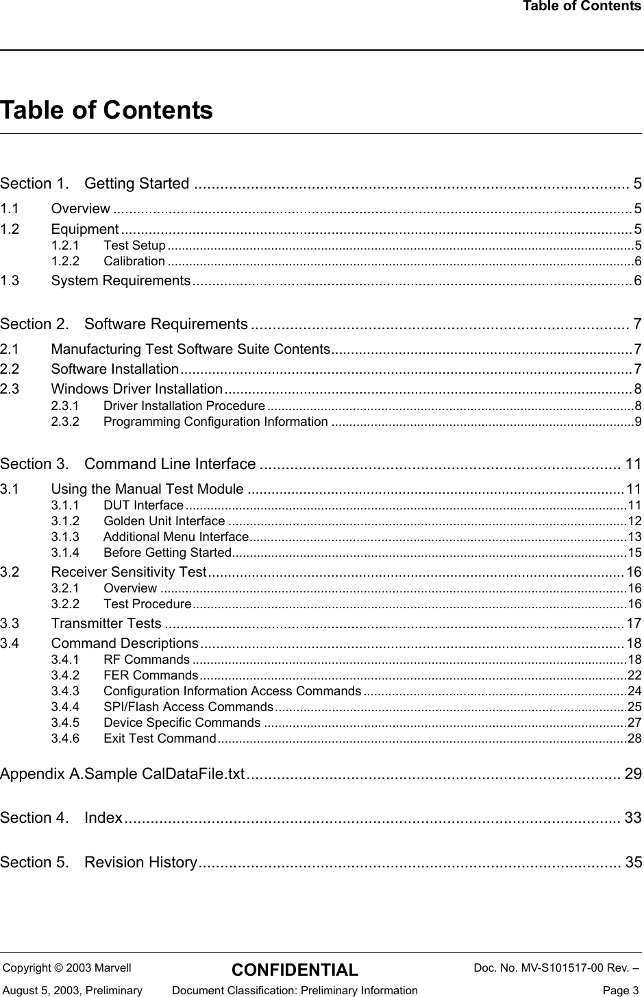

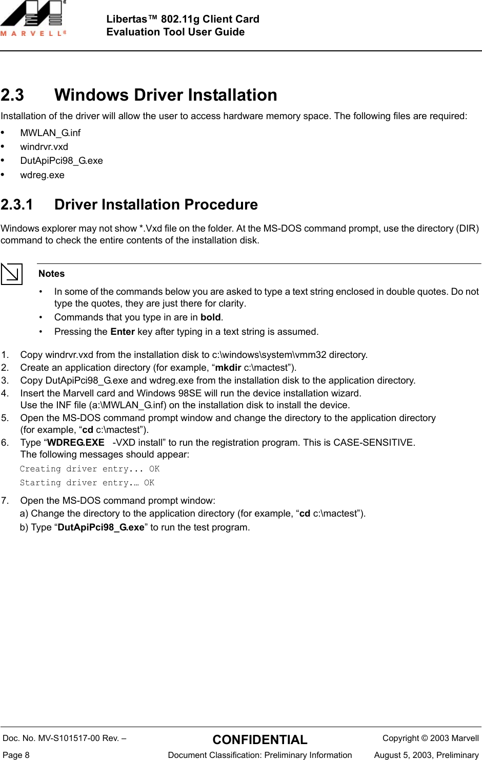

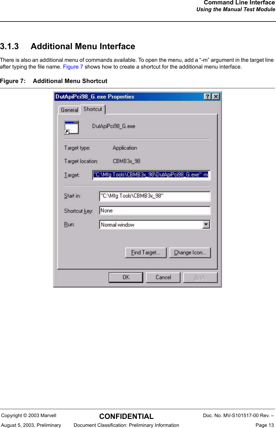
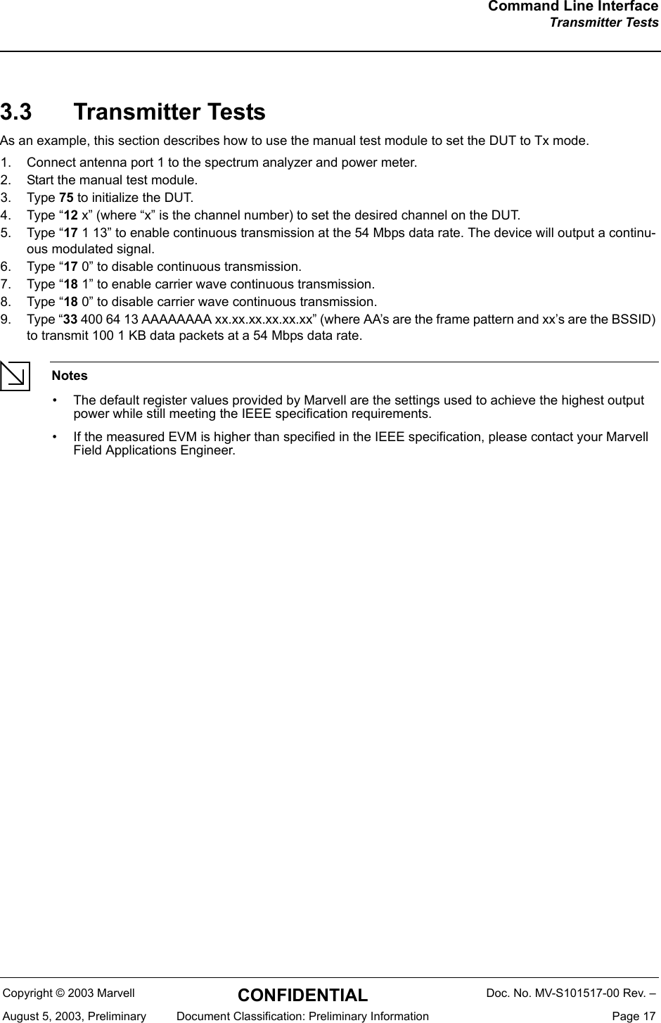
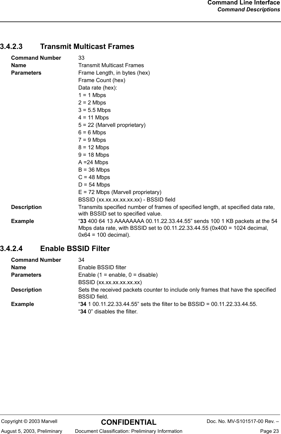
![Command Line InterfaceCommand DescriptionsCopyright © 2003 Marvell CONFIDENTIAL Doc. No. MV-S101517-00 Rev. –August 5, 2003, Preliminary Document Classification: Preliminary Information Page 193.4.1.4 Get Tx Power at PA3.4.1.5 Set Tx Power at PA3.4.1.6 Set Continuous Modulated Waveform Mode3.4.1.7 Set Continuous Waveform Transmission Mode3.4.1.8 Set Carrier Suppression Mode3.4.1.9 Set Channel and Power at Antenna with Calibration DataCommand Number 15Name Get Tx Power at PAParameters NoneDescription Returns the RF power settings.(RF power detector reference; predrive and polarization values).Example n/aCommand Number 16Name Set Tx Power at PA16 [RefDac [predriver [externalPApolarization]]Parameters Detector ReferencePredrivePolarizationDescription Sets the RF power.Example “16 [DetRef] [Predrive] [Polarization]”Command Number 17 [enable_dataRate]Name Set Continuous Modulated Waveform ModeParameters Enable (1 = enable, 0 = disable) data rateDescription Sets the device for continuous transmission of a modulated waveform.Example “17 1 13” sets the device for continuous transmission at the 54 Mbps data rate.“17 0” disables continuous transmission.Command Number 18Name Set Continuous Waveform Transmission ModeParameters Enable (1 = enable, 0 = disable)Description Sets the device to continuously transmit a carrier waveform.Example “18 1” sets the device to continuously transmit a carrier waveform.“18 0” disables this mode.Command Number 19Name Set Carrier Suppression Transmission ModeParameters Enable (1 = enable, 0 = disable)Description Sets the device for Carrier Suppression Transmission Mode.Example “19 1” sets the device for Carrier Suppression Transmission Mode.Command Number 22Name Set channel and RF power at antenna with calibration data for the channel](https://usermanual.wiki/Z-Com/0XG880M.Users-Manual/User-Guide-691928-Page-19.png)
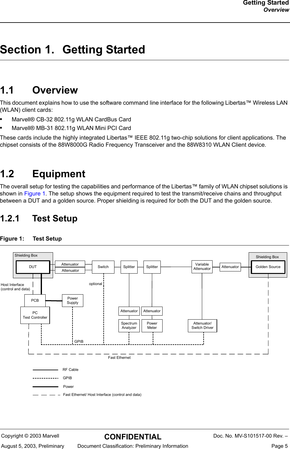
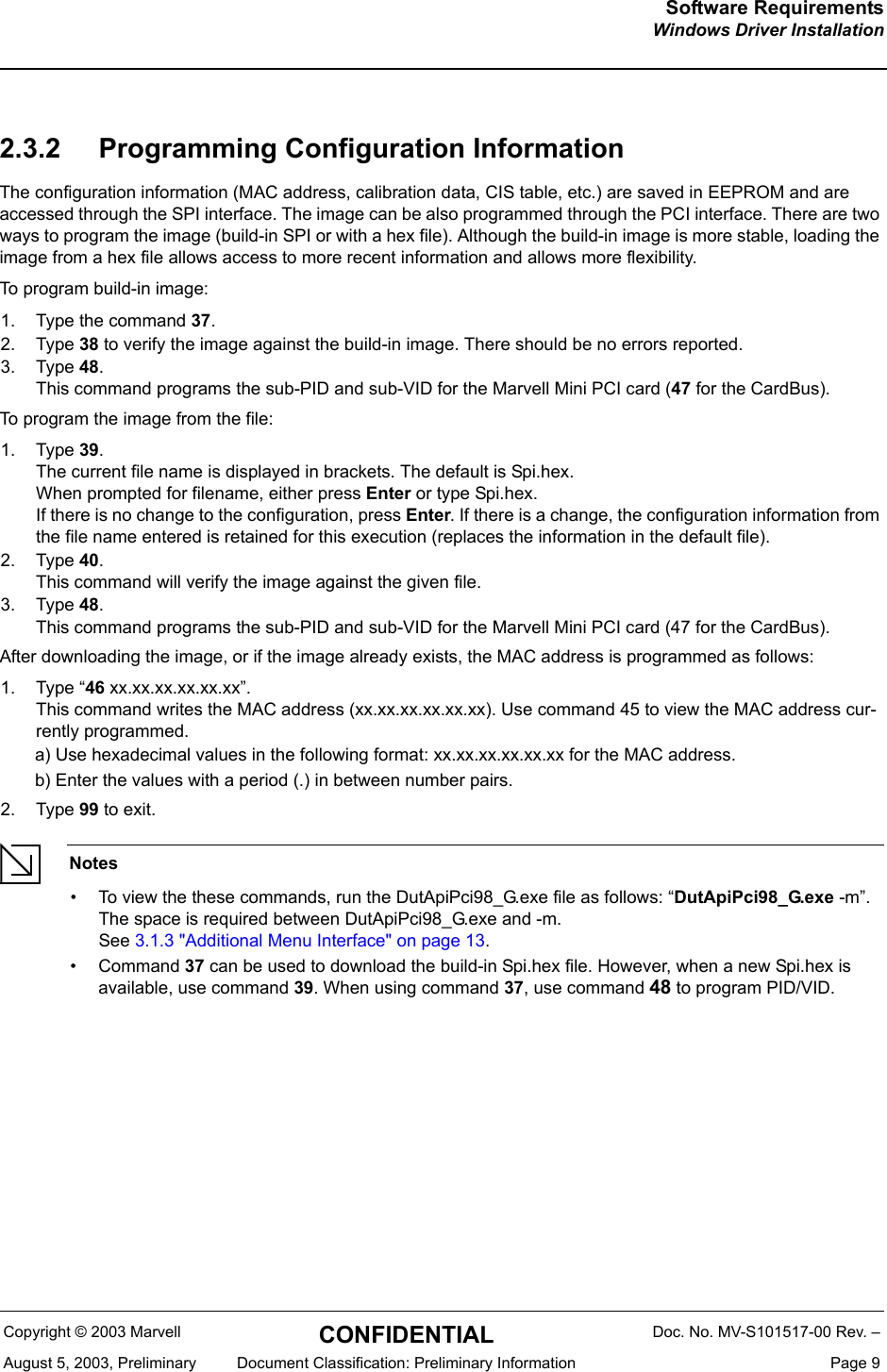
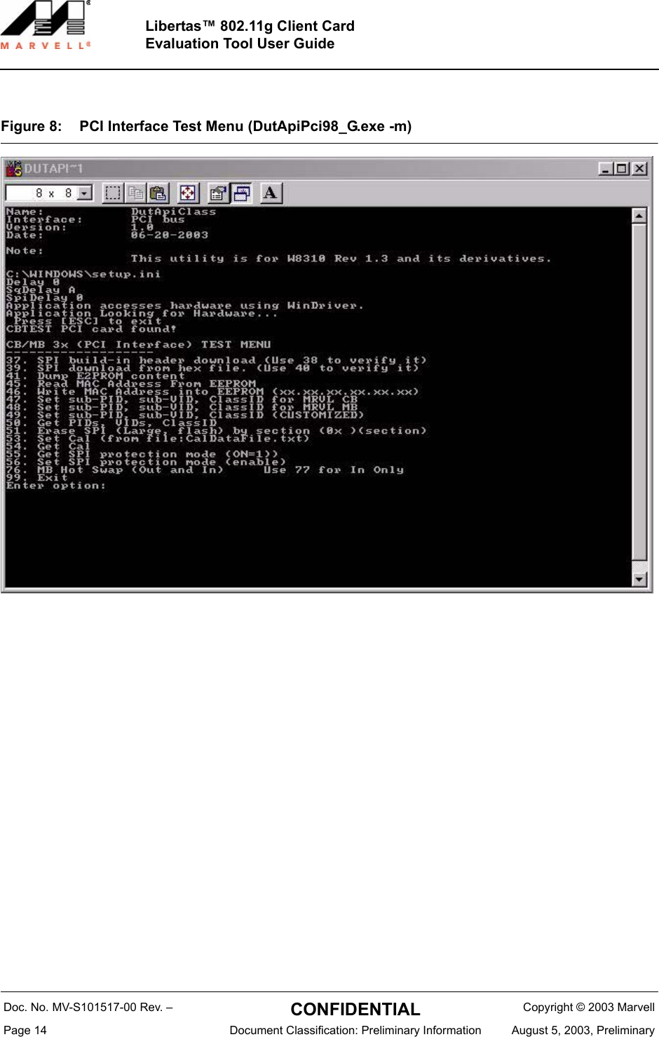
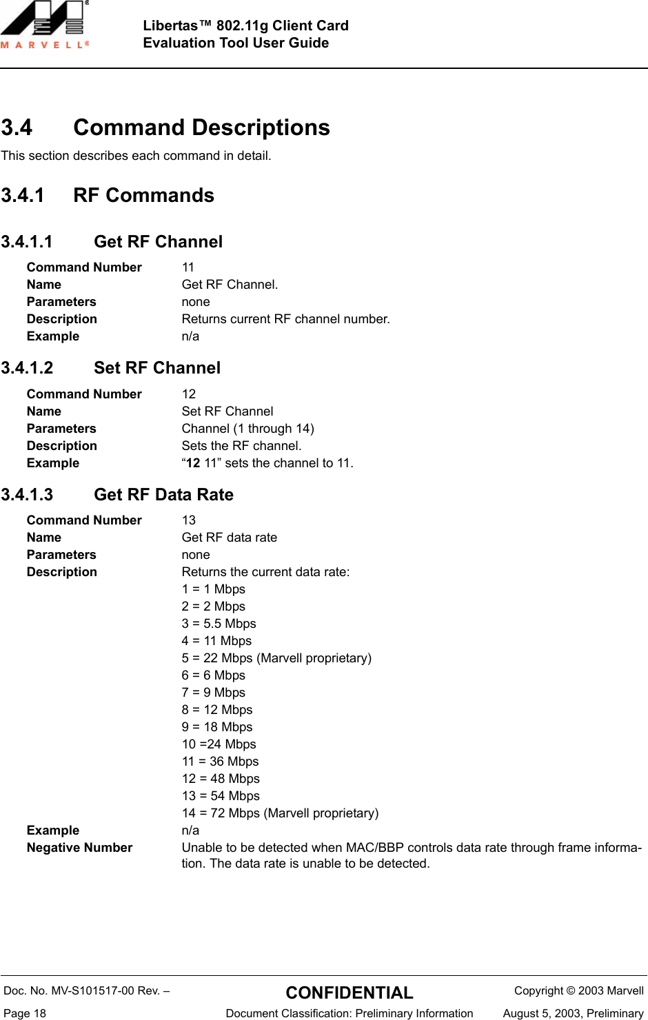
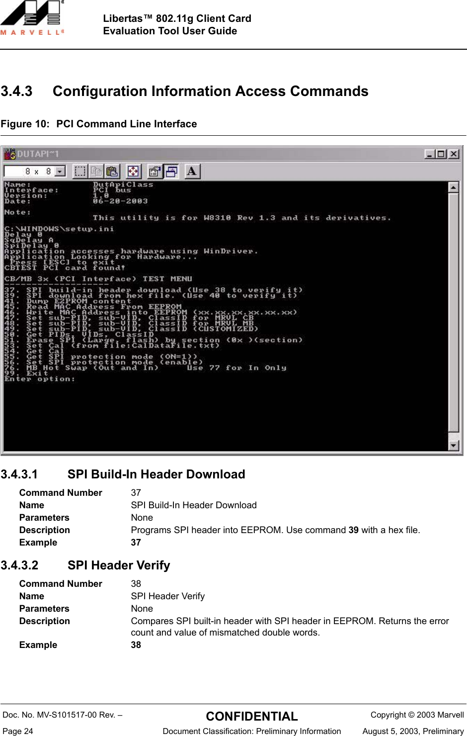
![Doc. No. MV-S101517-00 Rev. – CONFIDENTIAL Copyright © 2003 MarvellPage 22 Document Classification: Preliminary Information August 5, 2003, PreliminaryLibertas™ 802.11g Client CardEvaluation Tool User Guide3.4.2 FER Commands3.4.2.1 Clear Received Packet Counter3.4.2.2 Get Received Packet CounterNoteBecause of the timing difference in Reading the counters, if you are in an environment that has continuous traffic, MultiCPckt count could be larger than RxPckt count.Command Number 31Name Clear Received packet counterParameters noneDescription Clears the received packet counter.Example n/aCommand Number 32Name Get received packet counterParameters noneDescription Returns the following values:GetRxPckt: Number of correctly received packets (no CRC error), including unicast and multicast.GetRxMultiCPkt: Number of correctly received multicast packets (a subset of the first number).GetRxErrPckt: Number of received packets with CRC errors. Frame error rate based on detected packets [GetRxErrPckt/(GetRxPckt + GetRxErrPckt)].Example n/a](https://usermanual.wiki/Z-Com/0XG880M.Users-Manual/User-Guide-691928-Page-22.png)
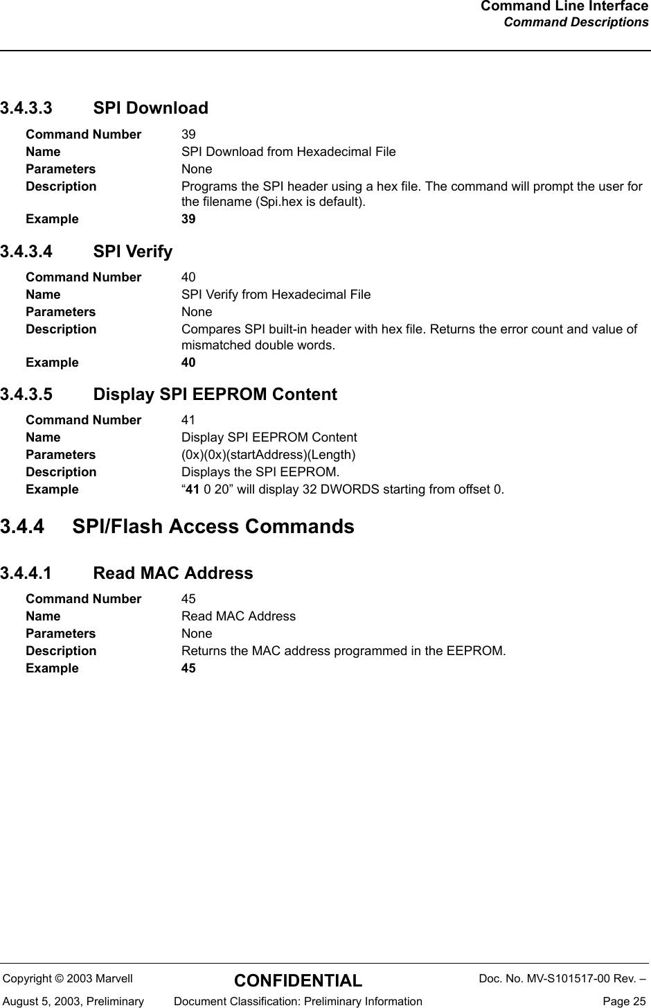
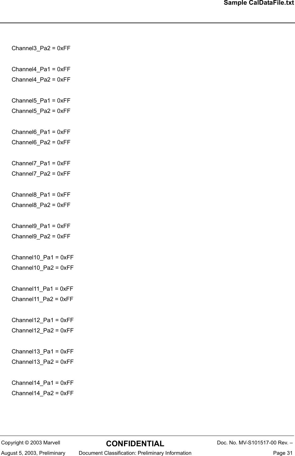
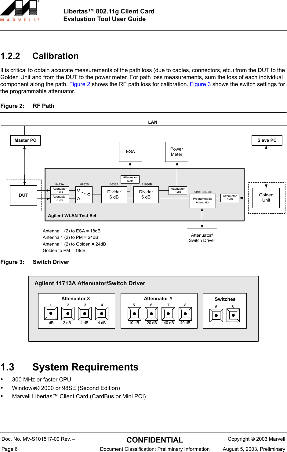
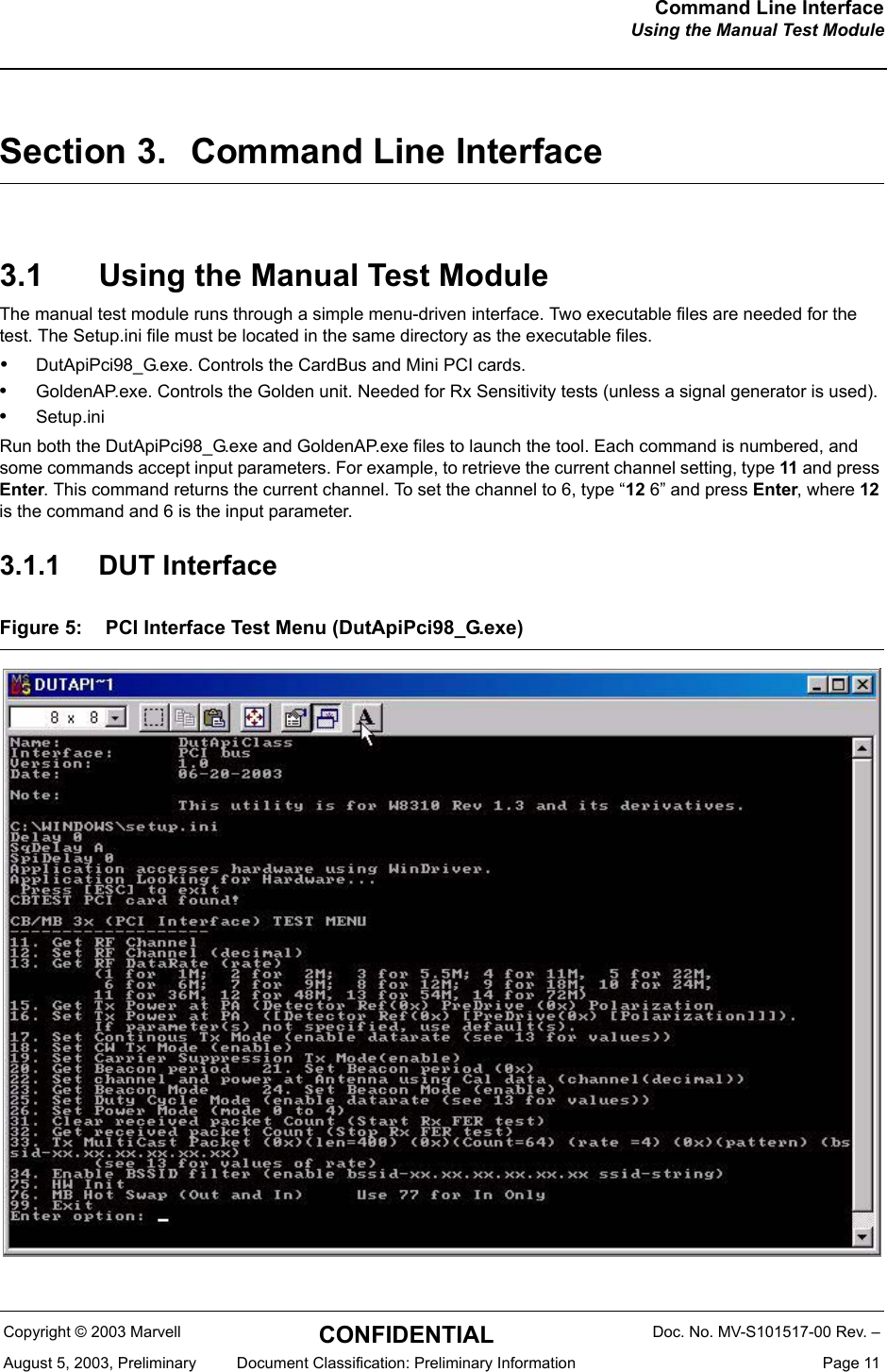
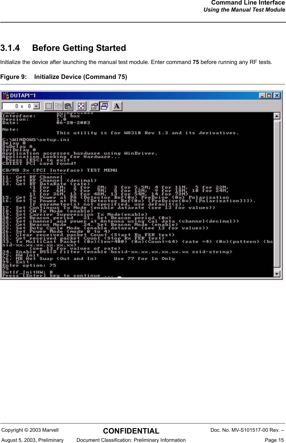
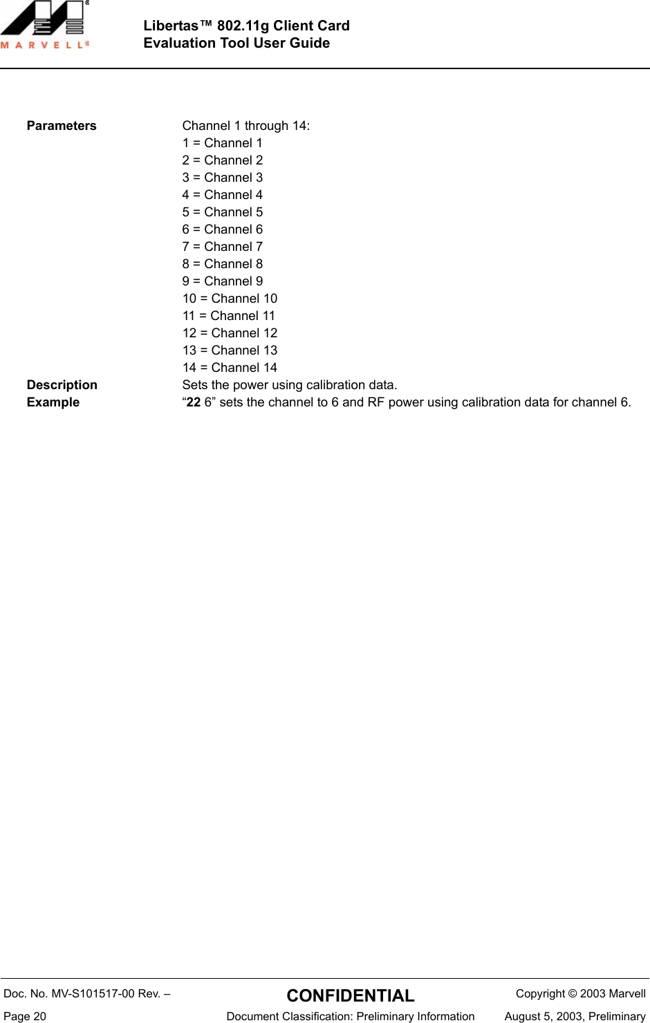
![Sample CalDataFile.txtCopyright © 2003 Marvell CONFIDENTIAL Doc. No. MV-S101517-00 Rev. –August 5, 2003, Preliminary Document Classification: Preliminary Information Page 29Appendix A. Sample CalDataFile.txt[Configuration]Board = MB31-001StructRev = 1Pa_External = 3AntHw =0x0a[LED]Led0 = 0xFFLed1 = 0xFFLed2 = 0xFFLed3 = 0xFF[CC]CC_primary = 0x10CC_secondary = 0xFF[CCA1]CCA_0 = 0xffCCA_1 = 0xffCCA_2 = 0xffCCA_3 = 0xff[CCA2]CCA_0 = 0xffCCA_1 = 0xffCCA_2 = 0xffCCA_3 = 0xff[Cus]Cus_0 = 0xffCus_1 = 0xff](https://usermanual.wiki/Z-Com/0XG880M.Users-Manual/User-Guide-691928-Page-29.png)
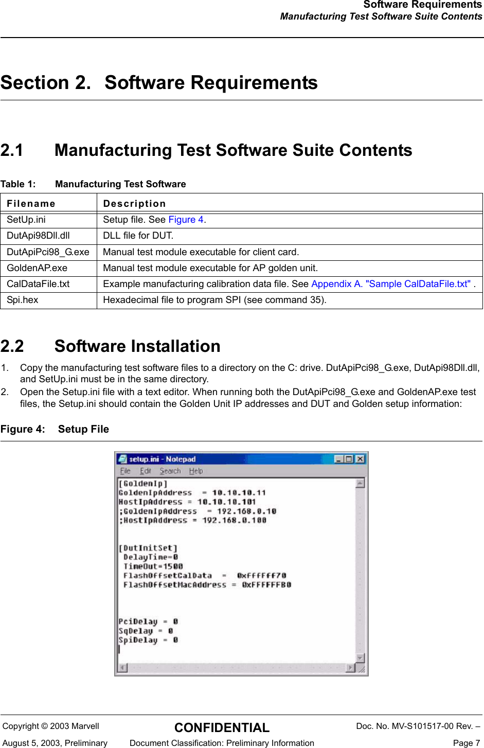
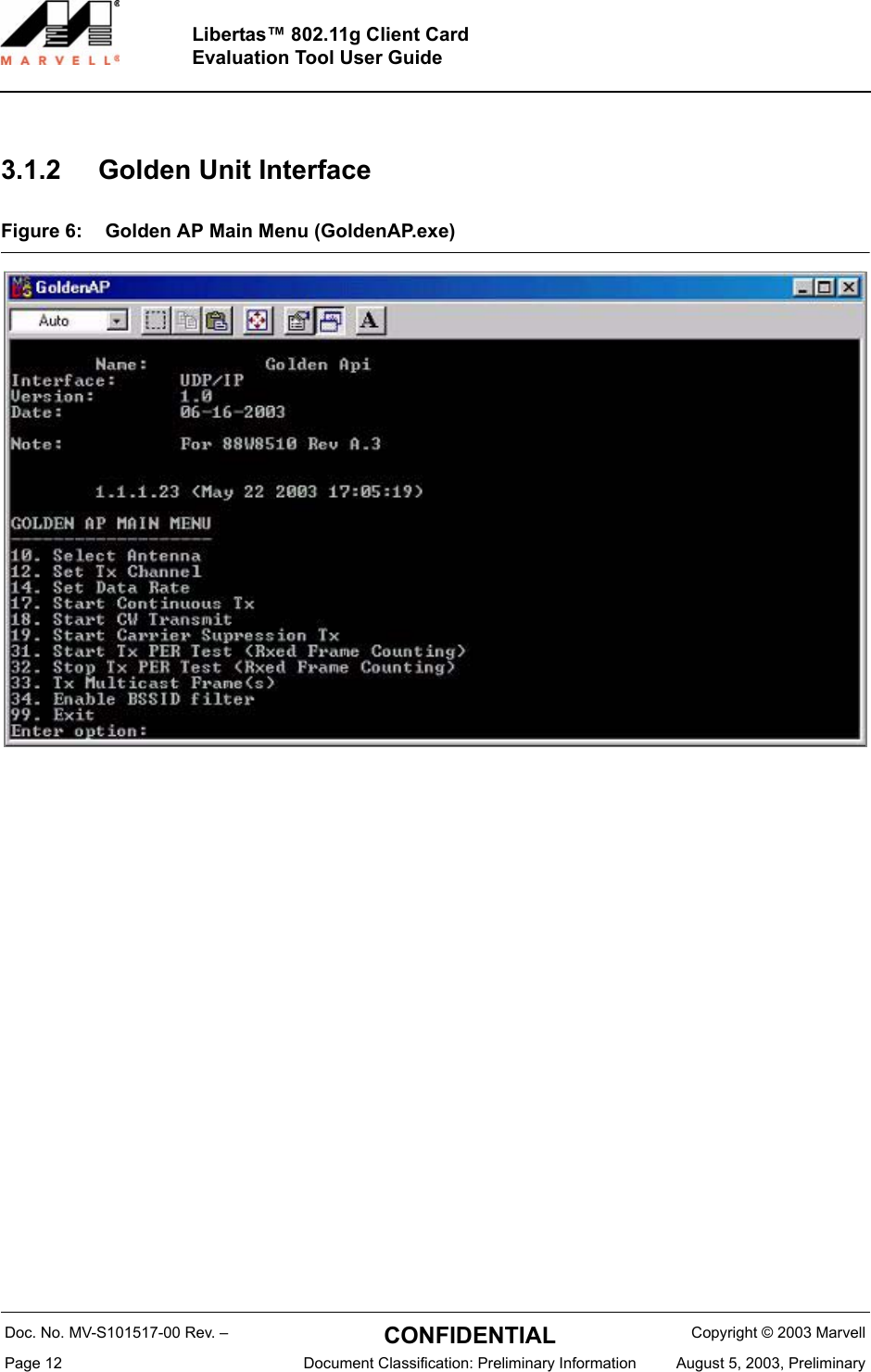
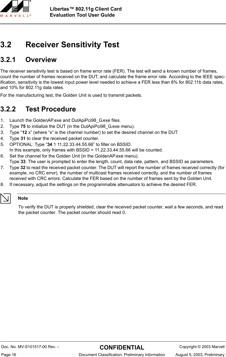
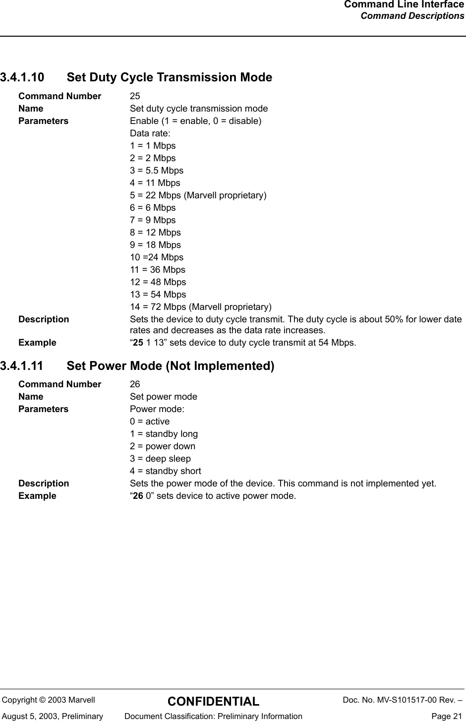
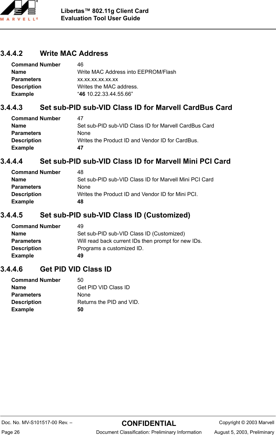
![Doc. No. MV-S101517-00 Rev. – CONFIDENTIAL Copyright © 2003 MarvellPage 30 Document Classification: Preliminary Information August 5, 2003, PreliminaryLibertas™ 802.11g Client CardEvaluation Tool User Guide[CalData]CalTableOption =1ant2NotCaled = 1ExtPaPolar_neg = 0 ExterPA_PartId = 0x3ExterPA_PreDriv = 0x4Xosc =1635;Channel1_Ant2Adjust =0;Channel1_Loss = 4;Channel1_Tune = 4Channel1_PDref = 0x60Channel2_PDref = 0x5eChannel3_PDref = 0x5cChannel4_PDref = 0x58Channel5_PDref = 0x58Channel6_PDref = 0x56Channel7_PDref = 0x54Channel8_PDref = 0x53Channel9_PDref = 0x53Channel10_PDref = 0x54Channel11_PDref = 0x56Channel12_PDref = 0x56Channel13_PDref = 0x56Channel14_PDref = 0x56Channel1_Pa1 = 0xFFChannel1_Pa2 = 0xFFChannel2_Pa1 = 0xFFChannel2_Pa2 = 0xFFChannel3_Pa1 = 0xFF](https://usermanual.wiki/Z-Com/0XG880M.Users-Manual/User-Guide-691928-Page-30.png)