Zhejiang Libiao Robotics LBAP-102LU-900 Wireless Communication Device User Manual
Zhejiang Libiao Robotics Co., Ltd. Wireless Communication Device
UserManual.wiki
>
Zhejiang Libiao Robotics
>
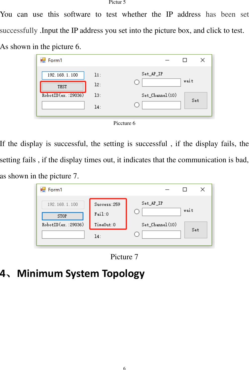
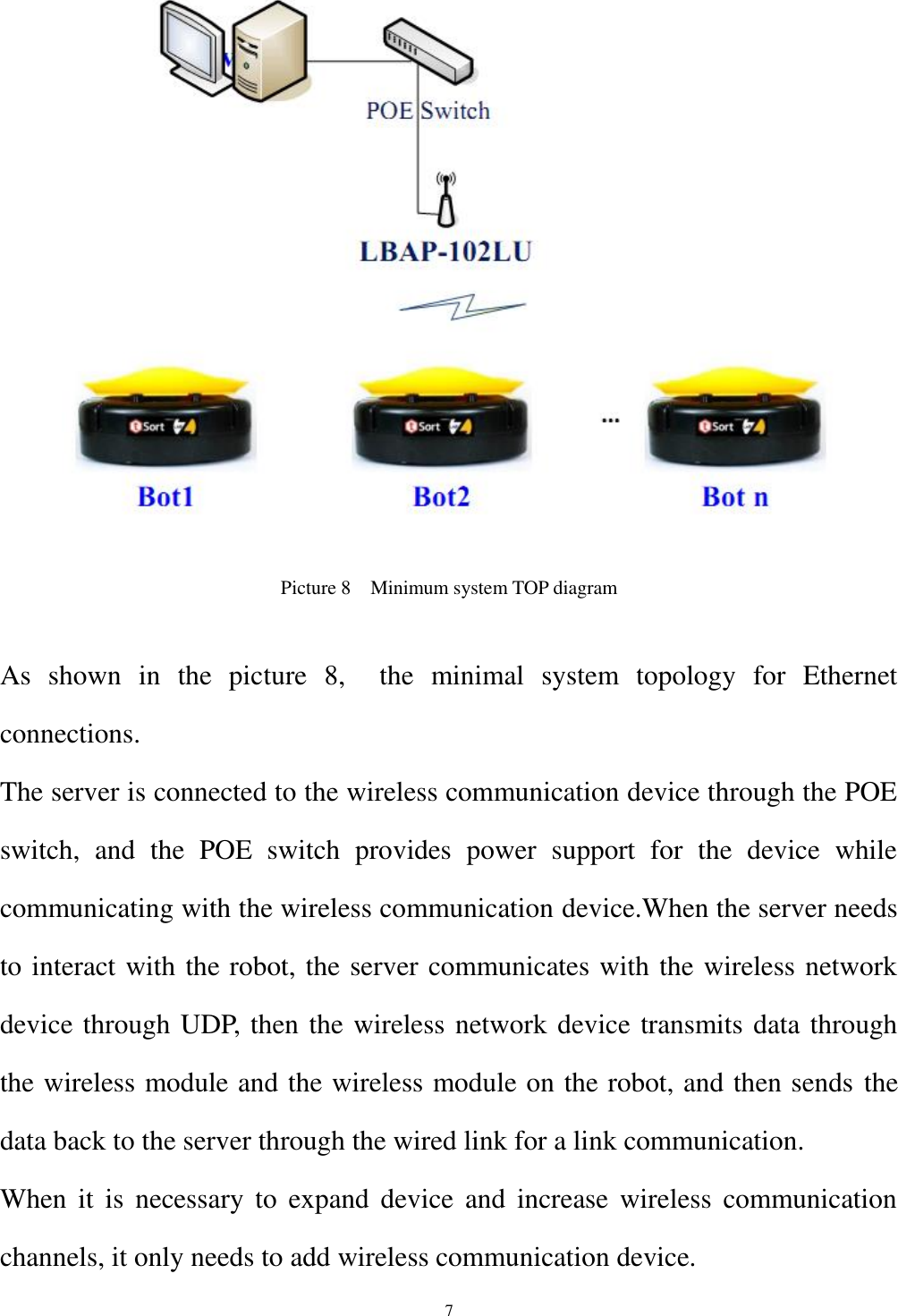
LBAP 102LU 900 User Manual
User Manual
Navigation menu
Upload a User Manual
Namespaces
Wiki Guide
HTML
PDF
Info
Views
User Manual
Discussion / Help
Navigation