Zida Technologies MB-A815EP-11 Mainboard User Manual Manual A815E1 indd
Zida Technologies Ltd. Mainboard Manual A815E1 indd
UserManual.wiki
>
Zida Technologies
>
MB-A815EP-11 User Manual
>
users manual 6
Contents
1.
users manual 1
2.
users manual 2
3.
users manual 3
4.
users manual 4
5.
users manual 5
6.
users manual 6
7.
users manual 7
users manual 6
Navigation menu
Upload a User Manual
Namespaces
Wiki Guide
HTML
PDF
Info
Views
User Manual
Discussion / Help
Navigation

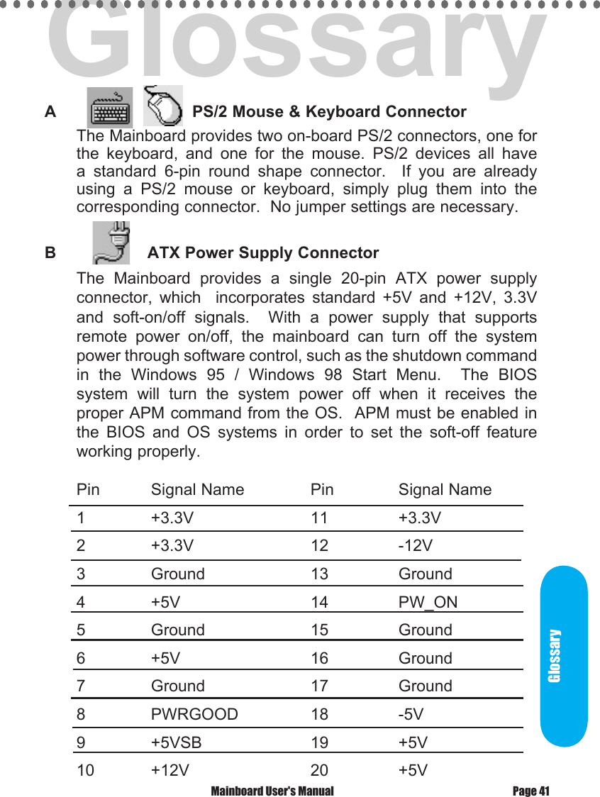
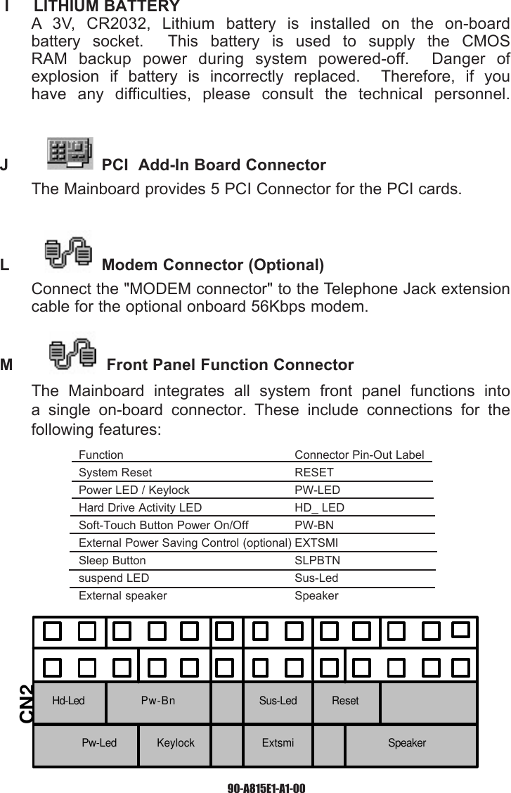
![GlossaryThe header pin-out is as follows:Pin . . . . . . . . . . . . . Signal Name1 . . . . . . . . . . . . . . . VCC, power source2 . . . . . . . . . . . . . . . No Connection3 . . . . . . . . . . . . . . . IRRX, infra-red receive4 . . . . . . . . . . . . . . . Ground5 . . . . . . . . . . . . . . . IRTX, infra-red transmitF Memory Module Sockets The Mainboard provides 168 pin standard DIMM sockets for installation of 3.3V unbuffered Single or Double Bank SDRAM modules.G Parallel Port ConnectorThe ATX Mainboard provides a parallel port connector. Based on the ATX standard, a 25-pin parallel port is now built on the mainboard back panel. This design makes the mainboard installation easier. The parallel port can be BIOS configured into standard (SPP) mode, Enhanced Parallel Port (EPP) mode, and a high speed Extended Capabilities Port (ECP) mode. EPP Mode requires a driver provided by the peripheral manufacturer in order to operate properly. H Accelerated Graphics Port [AGP] ConnectorThe Mainboard provides an AGP slot compatible with the Accelerated Graphics Port specification. AGP compliant video cards offer a much higher throughput than equivalent PCI bus video cards. PCI currently only supports a 33MHz bandwidth, and can transport at peak rates up to 133MB/s over its 32 bit data bus. AGP operates at a 66MHz bandwidth which enables a peak rate of 266MB/s in what is known as 'X1' mode. Using 'X2' mode, the peak transport rate can go as high as 532MB/s.Page 43 Mainboard User's Manual](https://usermanual.wiki/Zida-Technologies/MB-A815EP-11.users-manual-6/User-Guide-165863-Page-13.png)