Ziehl Abegg SE EMW RF Module MOSI09B User Manual
Ziehl-Abegg AG RF Module MOSI09B Users Manual
UserManual.wiki
>
Ziehl Abegg SE
>
EMW User Manual
>
Operating Instruction
Contents
1.
Installation Instruction
2.
Operating Instruction
Operating Instruction
Navigation menu
Upload a User Manual
Namespaces
Wiki Guide
HTML
PDF
Info
Views
User Manual
Discussion / Help
Navigation


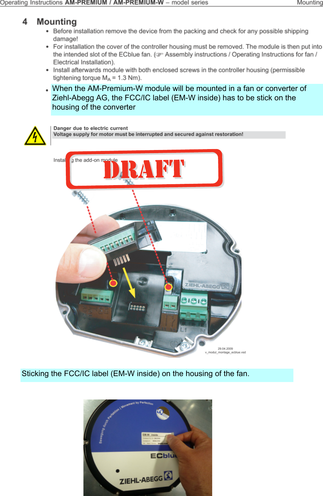


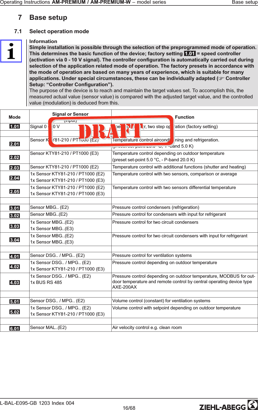

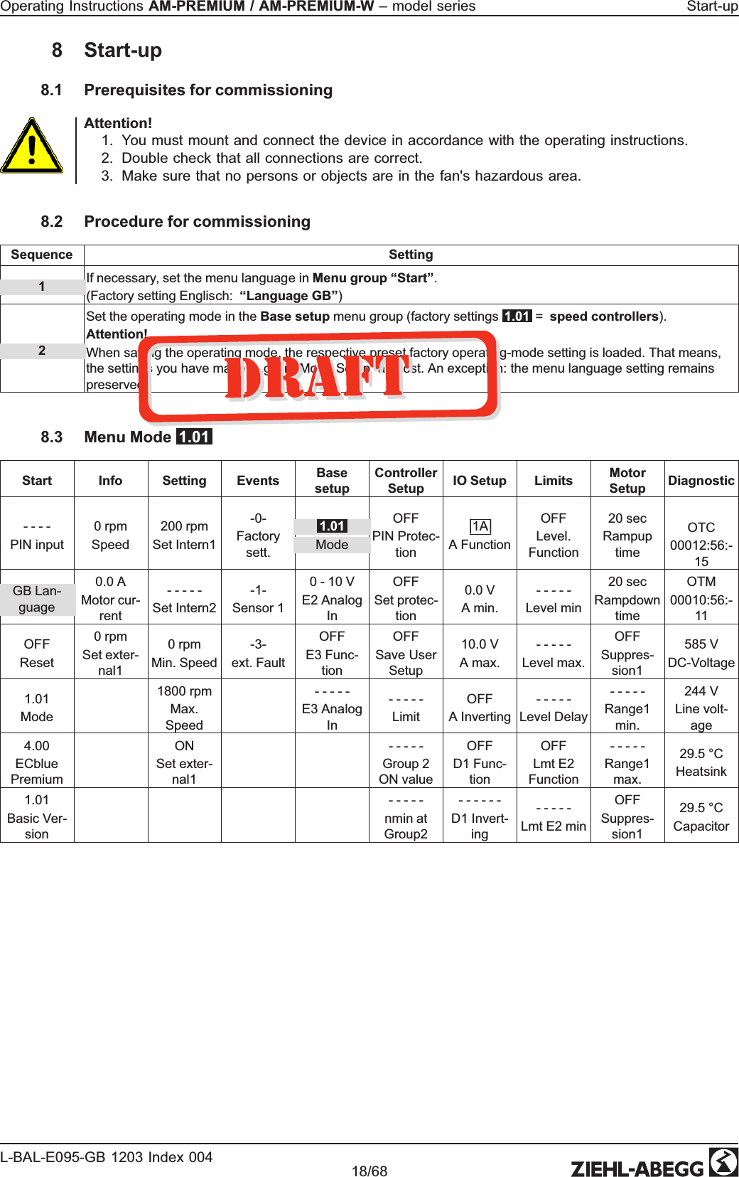

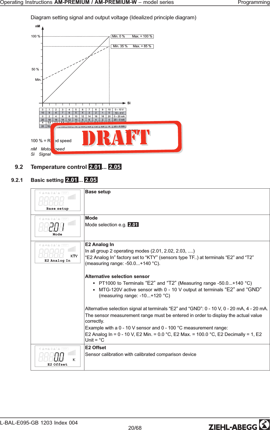


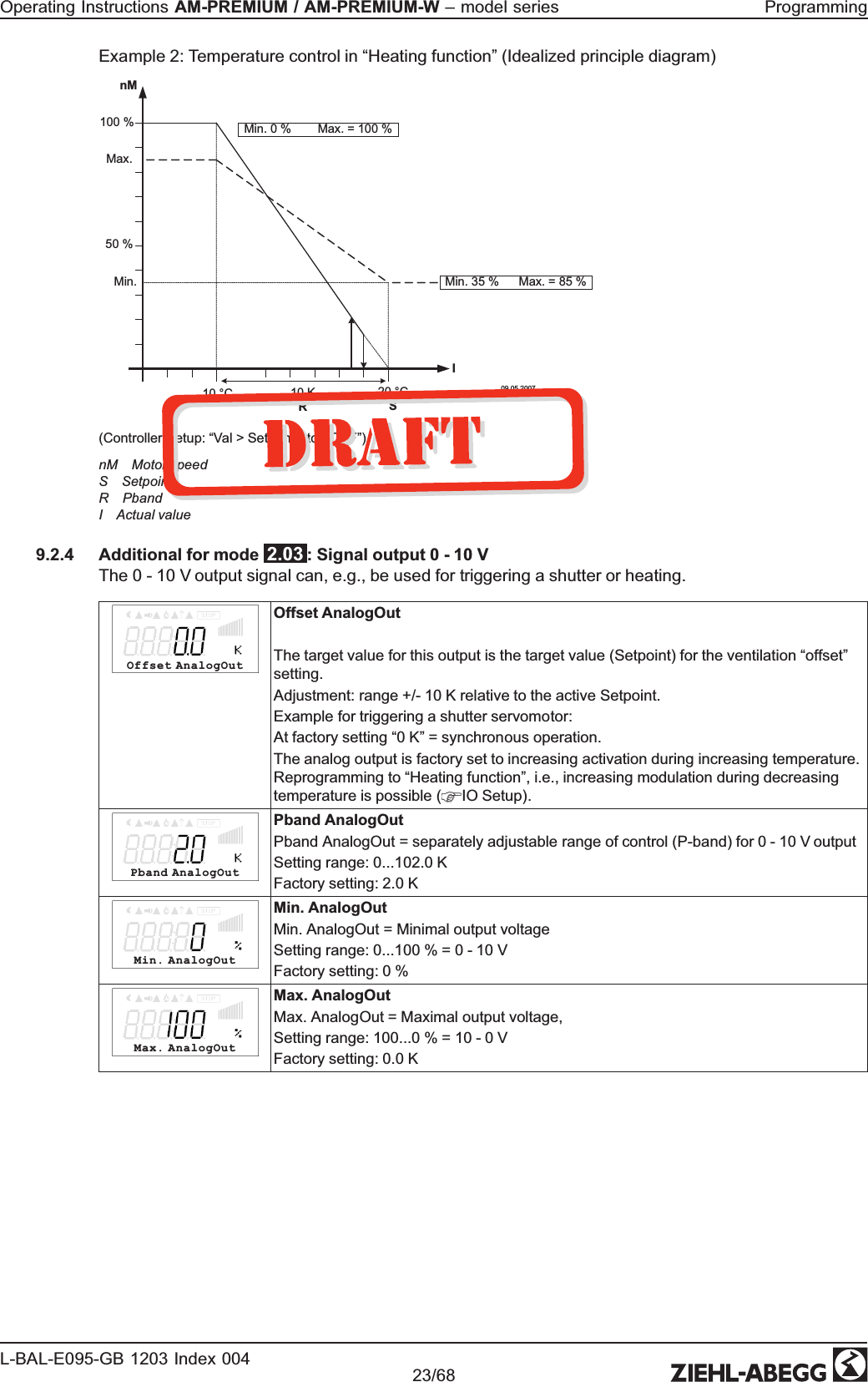
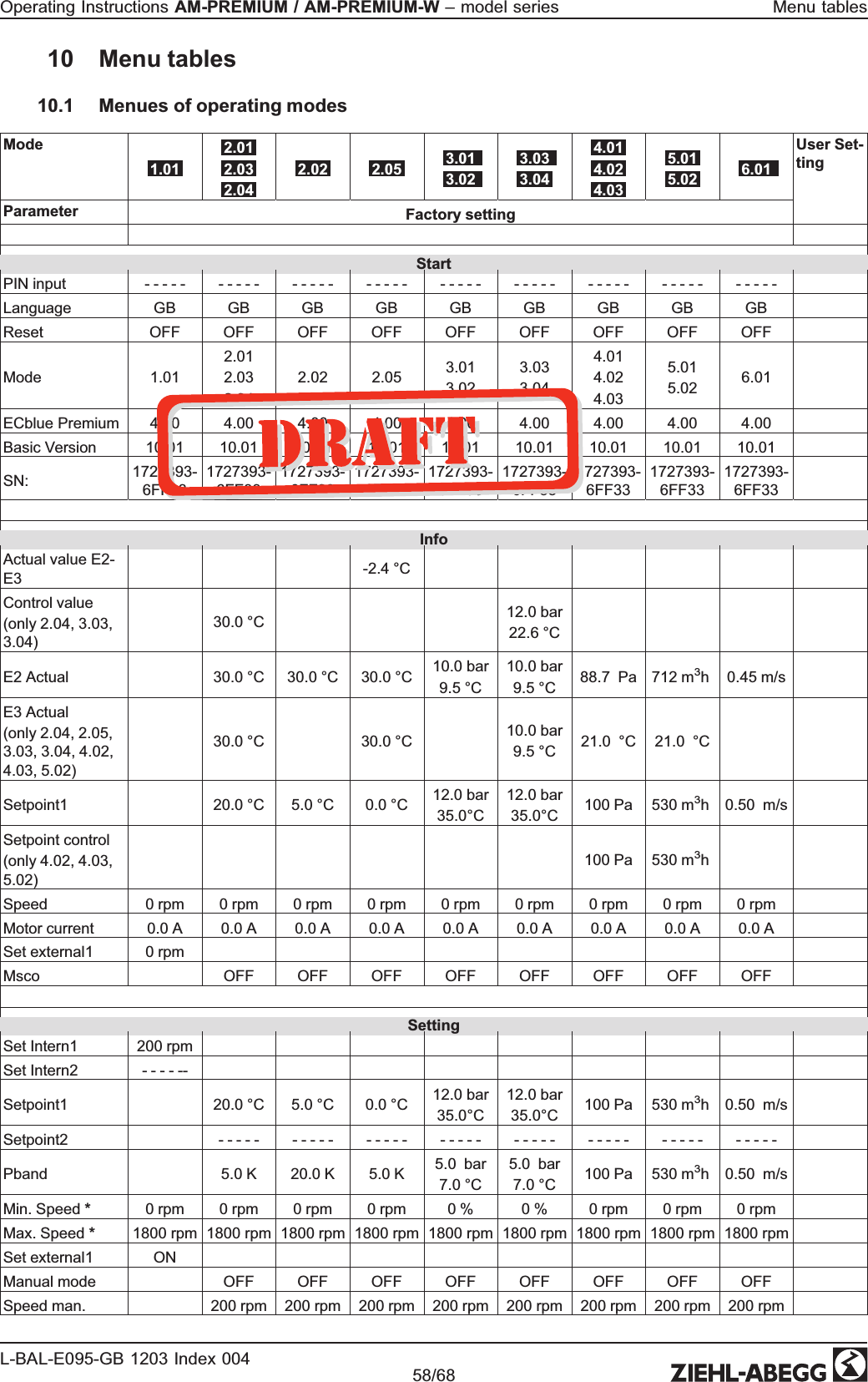
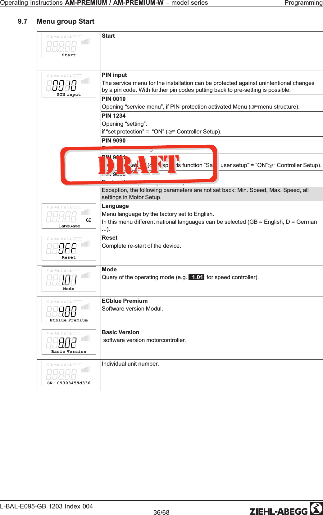
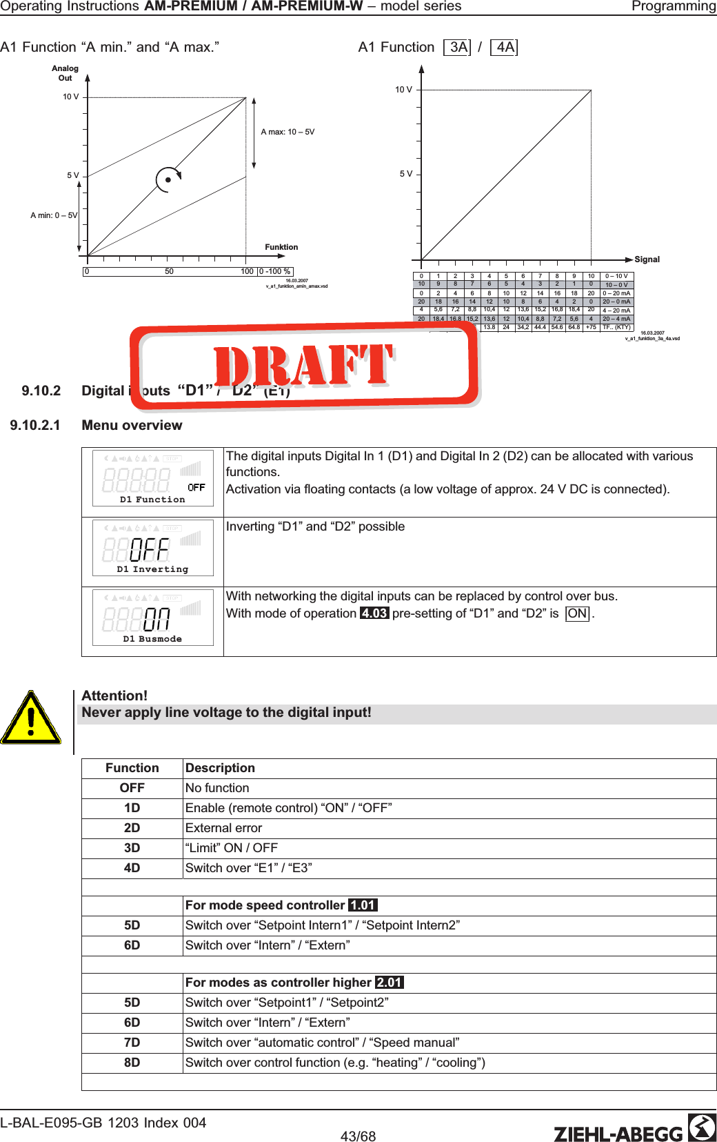
![Example for signal out 0 - 10 V (IO Setup: “A function” = |6A|) Max. Analog Out10 V50 %100 %IMin. Analog OutMin. 0 % Max. = 100 %Min. 35 % Max. = 85 %20 °CS10 KR 30 °C 09.05.2007v_signal_ausgang_0_10_v.vsdExample: Setpoint ventilation 25.0°C, Offset -5.0 K, Pband 10.0 K S Setpoint Ventilation +/- OffsetR PbandI Actual value9.2.5 For mode 2.03 : Relay output for Heating or Cooling OffsetDigitalOutOffsetDigitalOutOffset Digital Out = Offset for relay output (“K1” has to be reprogrammed to function |9K|). The relay operating point deviates by the adjusted offset of the Setpoint of the ventila-tion.Setting range: -10.0...+10.0 KFactory setting: -1.0 K•“0.0 K” set, i.e. heating “ON” when: actual value = Setpoint •During negative offset value heating “ON” when: actual value = Setpoint - offset •During positive offset value heating “ON” when: actual value = Setpoint + offset Hyst.DigitalOutHyst.DigitalOutSwitching hysteresis of the relaySetting range: 0...10 K, Factory setting: 1.0 K (Kelvin)Temperature variation with setting |9K| for K1 function in IO Setup e. g. for controlling a Heating. If the ambient temperature is lower than the set operating point, the heating remains switched on. If the ambient temperature exceeds the set operating point of the heating by 2 K (Kelvin), the heating is switched off. I.e., the release point is situated at the hysteresis value over the operating point.Example:Setpoint 15.0 °C, Offset +5.0 K, Hysteresis 2.0 KExample:Setpoint 20.0 °C, Offset -5.0 K, Hysteresis 2.0 K10121416182022242628301 3 5 7 9 11 13 15 17 19 21 23 25 27 29 [min] [°C]ON ON ONON = 15°C + 5 K = 20 °C OFF = 20°C + 2 K = 22 °C16.03.2007v_relais_heizen_9k_pos_offset.vsd10121416182022242628301 3 5 7 9 11 13 15 17 19 21 23 25 27 29 [min] [°C]ONOFF = 15°C + 2 K = 17 °C ON = 20°C - 5K = 15 °CON16.03.2007v_relais_heizen_9k_neg_offset.vsdE2 ActualThe activated heating is indicated over the fire symbol in the display.Operating Instructions AM-PREMIUM / AM-PREMIUM-W – model series ProgrammingL-BAL-E095-GB 1203 Index 004 Part.-No. 24/68](https://usermanual.wiki/Ziehl-Abegg-SE/EMW.Operating-Instruction/User-Guide-1785608-Page-25.png)
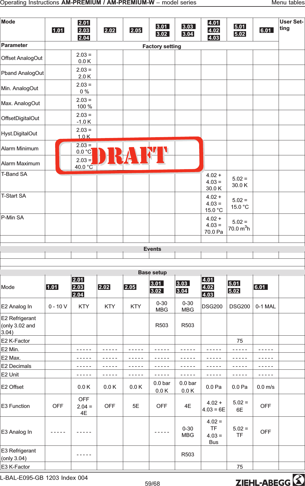
![Temperature variation with setting |10K| for “K1” function in IO Setup e. g. for activation of the cooling. Example:Setpoint 15.0 °C, Offset +5.0 K, Hysteresis 2.0 K10121416182022242628301 3 5 7 9 11 13 15 17 19 21 23 25 27 29 [min] [°C]ON ON ONON = 15°C + 5 K = 20 °C OFF = 20°C - 2 K = 18 °C16.03.2007v_relais_kuehlen_10k_pos_offset.vsdIf the ambient temperature is higher than the set operat-ing point, the cooling remains switched on. If the ambient temperature falls below the set operating point of the cooling by 2 K (Kelvin), it is switched off. I.e., the OFF point is situated at the hysteresis value under the ON point. 9.2.6 For mode 2.03 Relay output for temperature monitoring If the set value for the “minimum alarm” is not reached or the set value for the “maximum alarm” is exceeded, a message is generated via the alarm symbol in the display. In addition, „Lmt E1 min“ is displayed alternately with the actual value for the minimum alarm and Lmt E1 max for the „Maximum alarm“. An external message follows via the factory-assigned “K1” relay. (IO Setup: K1 function = |2K|). Alarm MinimumAlarm MinimumSetting range: OFF / -26.9...75.0 °CFactory setting: 0.0 °CAlarm MaximumAlarm MaximumSetting range: OFF / -26.9...75.0 °CFactory setting: 40.0 °CLmt E2 min.Example for display if falling below setting “Alarm Minimum” alternating to the actual value display. Relay “K1” disengages (if not inverted). Lmt E2 max.Example for display if exceeding setting “Alarm Maximum” alternating to the actual value display Relay “K1” disengages (if not inverted). Operating Instructions AM-PREMIUM / AM-PREMIUM-W – model series ProgrammingL-BAL-E095-GB 1203 Index 004 Part.-No. 25/68](https://usermanual.wiki/Ziehl-Abegg-SE/EMW.Operating-Instruction/User-Guide-1785608-Page-26.png)


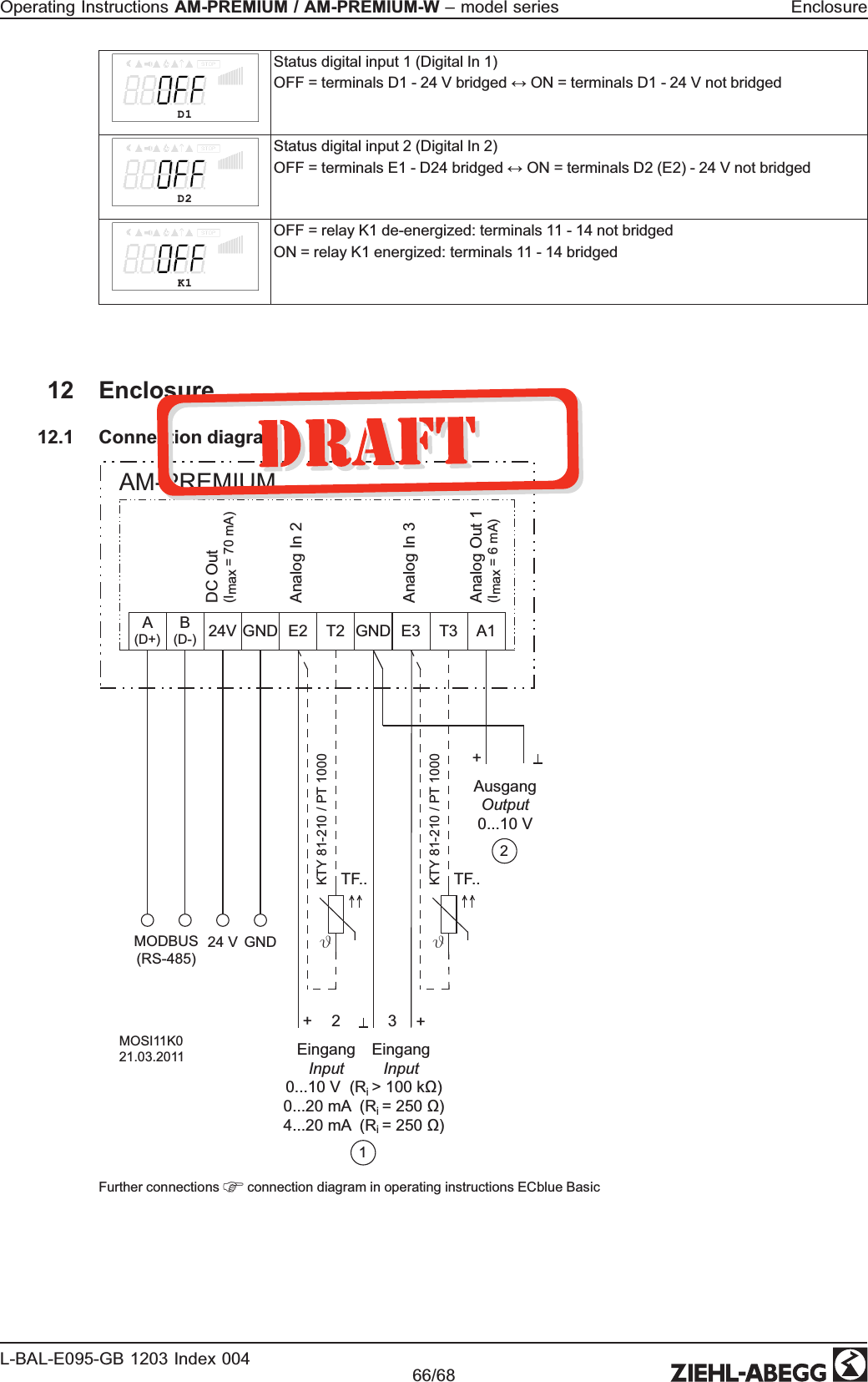
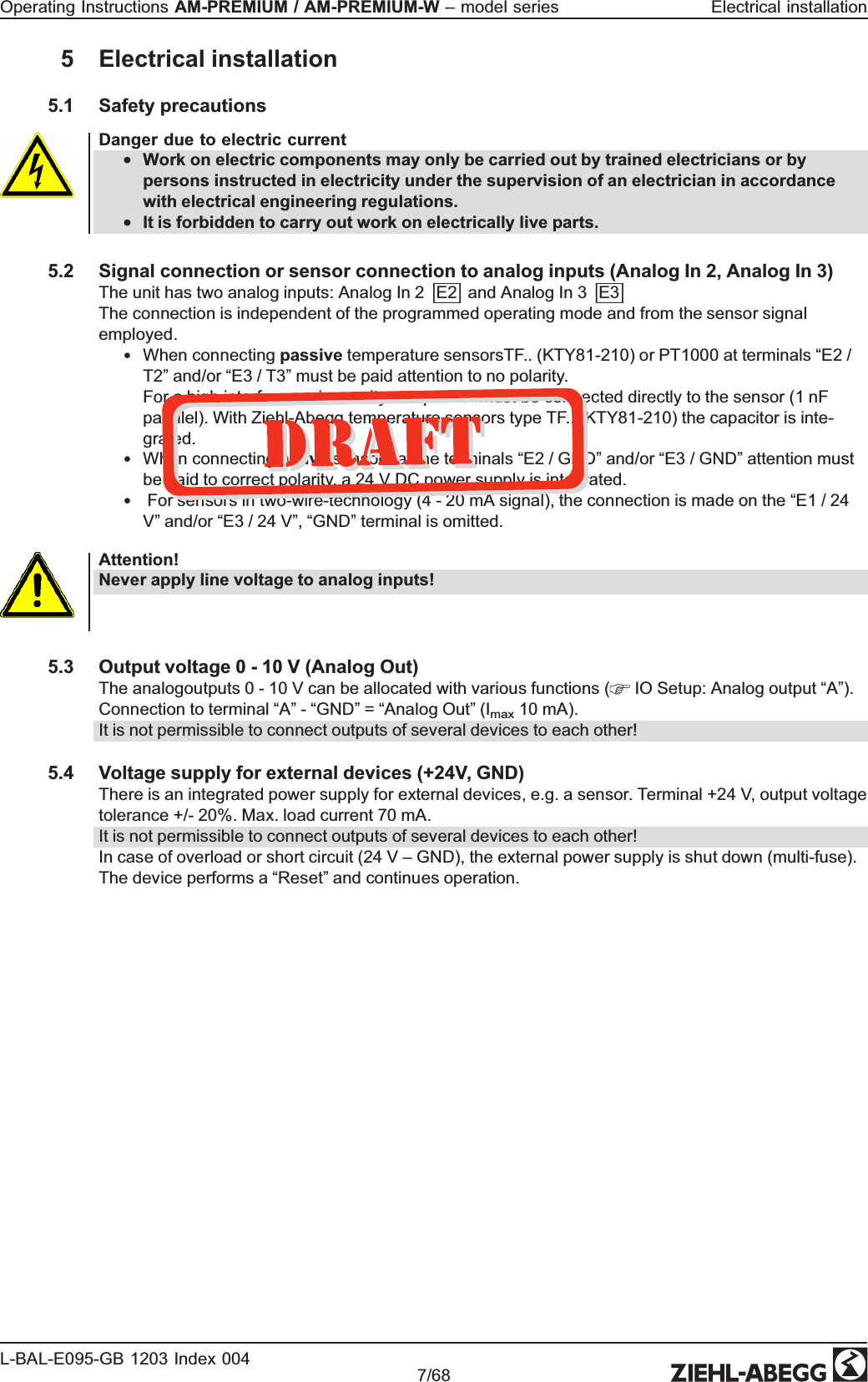
![Additional menu item for mode 4.02 and 4.03 with outside-temperature dependent target-setpoint. Outside-temperature dependent target-setpointAußentemperaturP-min SA[Pa] -15 °Cmin. Temperatur30 °CT-StartSollwert 1[Pa]Sollwert 2[Pa]07.02.2007v_sollwert_aussentemp_abhaengig_pa.vsdS1 Setpoint1S2 Setpoint2P-Min SA Minimum pressureT-min Minimum temperatureT-Start Setpoint reducing will start below this outside temperatureAT Outdoor temperatureAn outside temperature compensation can be activated (sensor connection “E2” = “Analog In 2”) when being operated as a pressure regula-tion device. An optimal building climate, e.g., can be achieved through this. Through this function, the set and active “Setpoint 1” or “Setpoint 2” is automatically changed proportional to the measured outside temperature ( Info: “Set-point control”). T-Band SAT-Band SATemperature range in which the setpoint change continiously with outside temperatureT-Start SAT-Start SASetpoint reducing will start below this outside temperatureP-Min SAP-Min SAMinimum pressure for very low outside temperatureOperating Instructions AM-PREMIUM / AM-PREMIUM-W – model series ProgrammingL-BAL-E095-GB 1203 Index 004 Part.-No. 31/68](https://usermanual.wiki/Ziehl-Abegg-SE/EMW.Operating-Instruction/User-Guide-1785608-Page-32.png)

![PbandPbandNarrow control range = Short control timesWide control range = Longer control times and more stable controlSetting range: depending on measuring range of sensor and “K factor”Factory setting: 530 m3/h Min. SpeedMin. SpeedSetting range: 0 rpm... “Max. Speed”Factory setting: 0 rpmMax. Speed Max. Speed Setting range: Rated speed...0 rpm (takes priority over setting “Min. Speed”) Factory setting: Rated speedManual modeManual mode“OFF” = automatic control as function of the set parameters (Factory setting) “ON” = automatic control without function, speed setting in menu “Speed manual”Speed man.Speed Manual modeManual speed setting without influence by the external signal.Activation by menu “Manual mode” or external contact at digital input ( IO Setup). Setting range: 0 rpm...Rated speed, Factory setting: 200 rpmFor information about deactivated regulation the adjusted value for manual speed is indicated alternating with the actual value.Additional menu item for mode 5.02 with outside-temperature dependent target-setpoint Outside-temperature dependent target-setpointAußentemperaturP-min SA[m3/h]-15 °Cmin. Temperatur30 °CT-StartSollwert 1[m3/h]Sollwert 2[m3/h]07.02.2007v_sollwert_aussentemp_abhaengig_m3h.vsdS1 Setpoint1S2 Setpoint2P-Min SA Minimum air volumeT-min Minimum temperatureT-Start Setpoint reducing will start below this outside temperatureAT Outdoor temperatureAn outside temperature compensation can be activated (sensor connection “E2” to “Analog In 2”) when being operated as a air volume regu-lation device. An optimal building climate, e.g., can be achieved through this. Through this function, the set and active Setpoint 1/2 is automatically changed proportional to the measured outside temperature ( Info: “Setpoint control”). T-Band SAT-Band SATemperature range in which the setpoint change continiously with outside temperatureT-Start SAT-Start SASetpoint reducing will start below this outside temperatureP-Min SAP-Min SAMinimum pressure for very low outside temperatureOperating Instructions AM-PREMIUM / AM-PREMIUM-W – model series ProgrammingL-BAL-E095-GB 1203 Index 004 Part.-No. 33/68](https://usermanual.wiki/Ziehl-Abegg-SE/EMW.Operating-Instruction/User-Guide-1785608-Page-34.png)


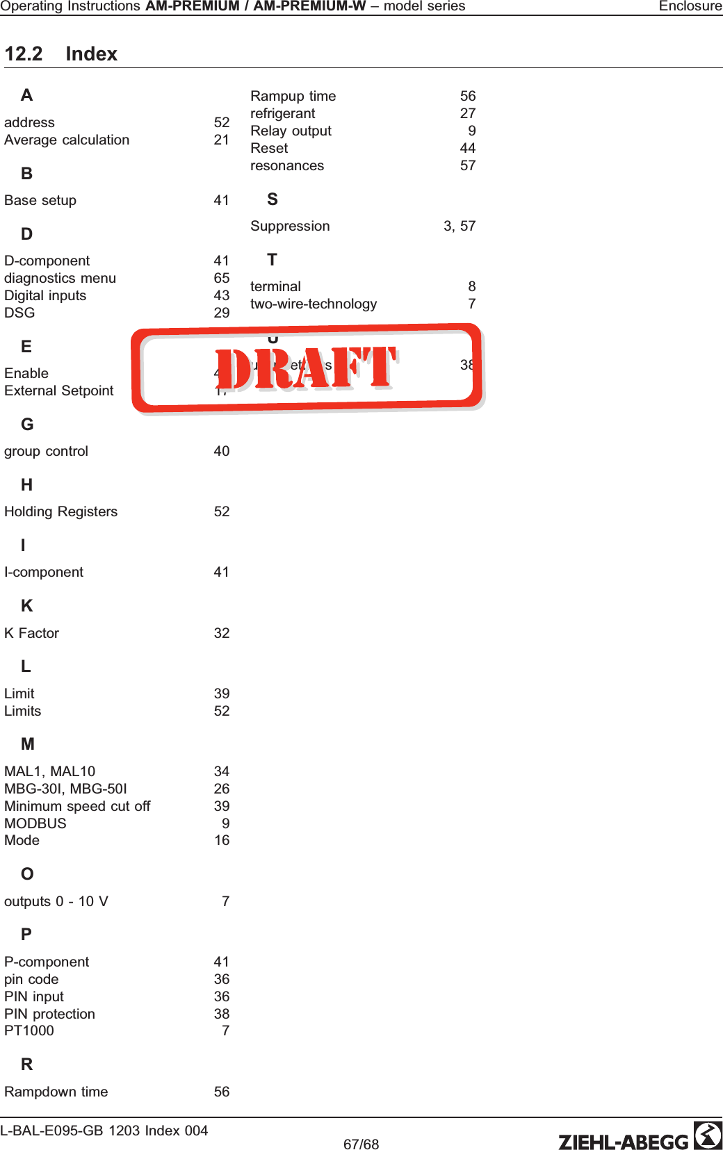
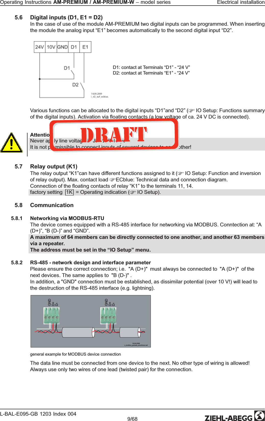
![Example for Mode “1.01” with speed setting signal 0 - 10 V n [%]Si E0 1 2 3 4 5 6 7 8 9 10 0 – 10 V 16.11.2009v_e2_modus_1_prz.vsd1Modus 1E2 min. = 0 %, E2 max. = 100 %1002E2 min. = 25 %, E2 max. = 100 %806040203E2 min. = 20 %, E2 max. = 80 %E2 min. = 0 %, E2 max. = 80 %4Modus 1Example: “E2 min.” = 20 % The controller begins only at approx. 20% higher signal with minimal speed.Example: “E2 max.” = 80 % Speed rises linear to 100% speed with 80% setting signal.Si E0 1 2 3 4 5 6 7 8 9 10 0 – 10 V16.11.2009v_e2_modus_2_prz.vsd1Modus 2E2 min. = 0 %, E2 max. = 100 %1002E2 min. = 40 %, E2 max. = 100 %806040203E2 min. = 30 %, E2 max. = 90 %E2 min. = 0 %, E2 max. = 80 %4n [%]Modus 2Example: “E2 min.” = 30 % Only with approx. 30 % setting signal the controller begins with approx. 30% speed.Example: “E2 max.” = 80 % Over 80 % setting signal the speed is switched to 100 %. n = speed of motor, Si E = setting signal input Idealized principle diagrams for setting: “Min. Speed” = 0 % and “Max. Speed” = 100 % 9.10.3.2 Inverting analog inputs “E2” / “E3”After programming the signal or sensor type, an inversion of the inputs can be carried out.E2 InvertingFactory setting for Inverting inputs = “OFF” (if input activated) (signal: 0 - 10 V, 0 - 20 mA, 4 - 20 mA). For activation using inverted default signals or sensors with inverted output signals proportional to the measurement range, switch inverting to “ON” (Signal: 10 - 0 V, 20 - 0 mA, 20 - 4 mA). E3 InvertingOperating Instructions AM-PREMIUM / AM-PREMIUM-W – model series ProgrammingL-BAL-E095-GB 1203 Index 004 Part.-No. 50/68](https://usermanual.wiki/Ziehl-Abegg-SE/EMW.Operating-Instruction/User-Guide-1785608-Page-51.png)


![9.11.3 Limit indication depending on (offset) to SetpointIn operating modes as a controller (via 2.01 ), two limit indicators can be carried out based on the set target value (Setpoint) and measured actual value (on E2). Offset FunctionFollowing functions can be allocated to the limit indicationOFF without function1L Indication with the centralized fault of a programmed relay (IO allocation function |2K|) warning symbol in display, “AL” code in events memory. 2L Is merely displayed in the events menu as message “msg”. In the IO setup, a separate relay can be allocated independent of these settings. Offset 1Offset 1, Offset 2Both values for Offset 1 and Offset 2 can be set independent of each other and act on a relay together if correspondingly programmed. If a function is activated or if a relay is allocated both settings (Offset 1 and Offset 2) are initially at “OFF”. Work can be carried out with one as well as with both limit indicators.“Offset 1” for alarm in case of an exceeding of the max. deviation between actual and target. Switch ON point: actual value = Setpoint +/- offsetSwtich OFF point: Actual value by hysteresis under the switch-on point“Offset 2” for alarm in case of an undercutting of the max. deviation between actual and target Switch ON point: actual value = Setpoint +/- offsetSwtich OFF point: Actual value by hysteresis over the switch-on pointOffset 2Offset Hyst.Offset HysteresisHysteresis switch-on point: In temperature regulation + / - 10 K, otherwise sensors 10 % of measurement rangeOffset Del.Offset DelayTime delay until indication through relay and alarm symbol.Setting range: 0 - 120 sec.Factory setting: 2 sec.Example for temperature regulation; for other modes of operation settings in corresponding sensor unit.Offset 1 for alarm during exceeding10121416182022242628301 3 5 7 9 11 13 15 17 19 21 23 25 27 29 [min] [°C]ON ON ONON = 15°C + 5 K = 20 °C OFF = 20°C - 2 K = 18 °C16.03.2007v_relais_kuehlen_10k_pos_offset.vsdExample: Setpoint 15.0 °C, Offset +5.0 K, Hysteresis 2.0 KOffset 2 for alarm during undercutting10121416182022242628301 3 5 7 9 11 13 15 17 19 21 23 25 27 29 [min] [°C]ONOFF = 15°C + 2 K = 17 °C ON = 20°C - 5K = 15 °CON16.03.2007v_relais_heizen_9k_neg_offset.vsdExample: Setpoint 15.0° C, Offset -5.0 K, Hysteresis 2.0 KOperating Instructions AM-PREMIUM / AM-PREMIUM-W – model series ProgrammingL-BAL-E095-GB 1203 Index 004 Part.-No. 55/68](https://usermanual.wiki/Ziehl-Abegg-SE/EMW.Operating-Instruction/User-Guide-1785608-Page-56.png)