nTAG Interactive 400-00200 Access Point Radio User Manual
nTAG Interactive LLC Access Point Radio
UserManual.wiki
>
nTAG Interactive
>
400 00200 User Manual
User manual
Navigation menu
Upload a User Manual
Namespaces
Wiki Guide
HTML
PDF
Info
Views
User Manual
Discussion / Help
Navigation
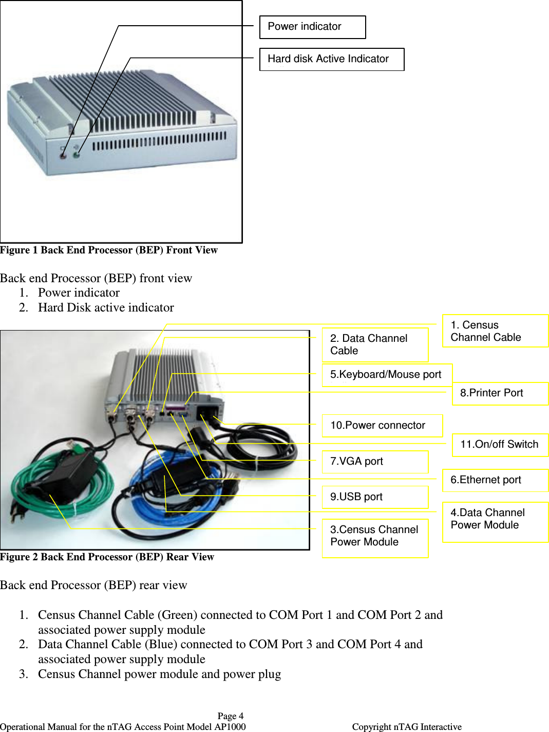
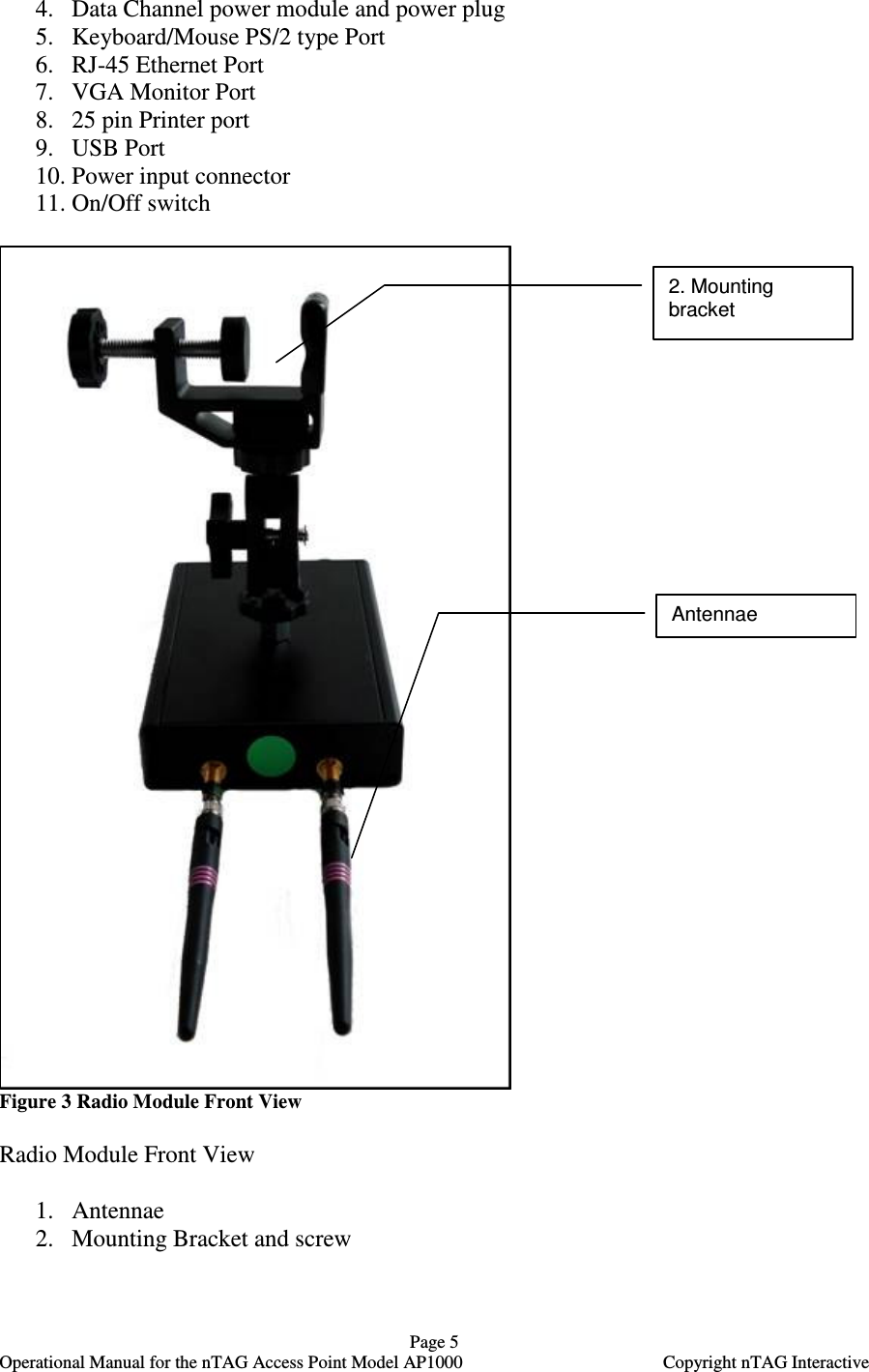
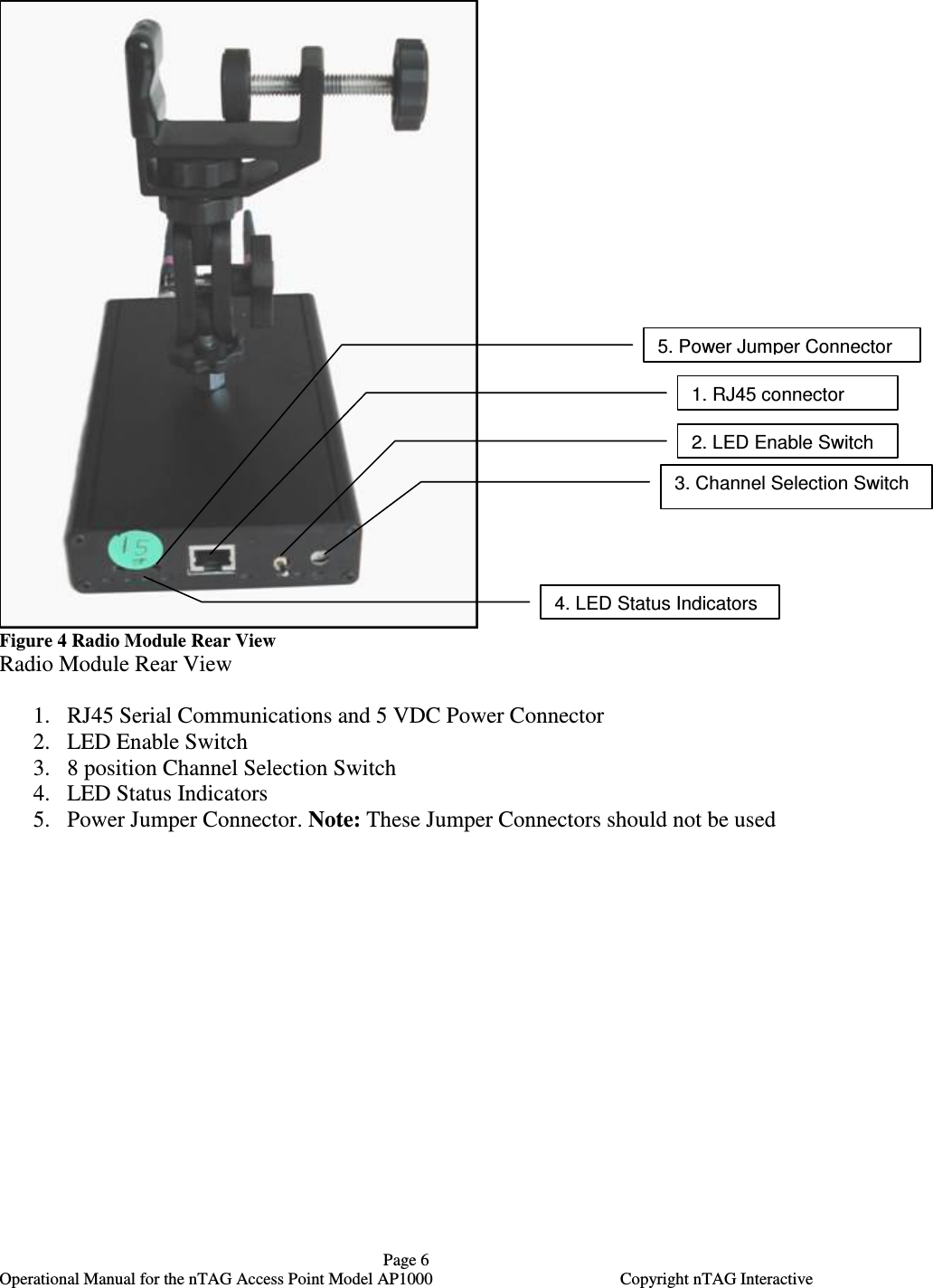
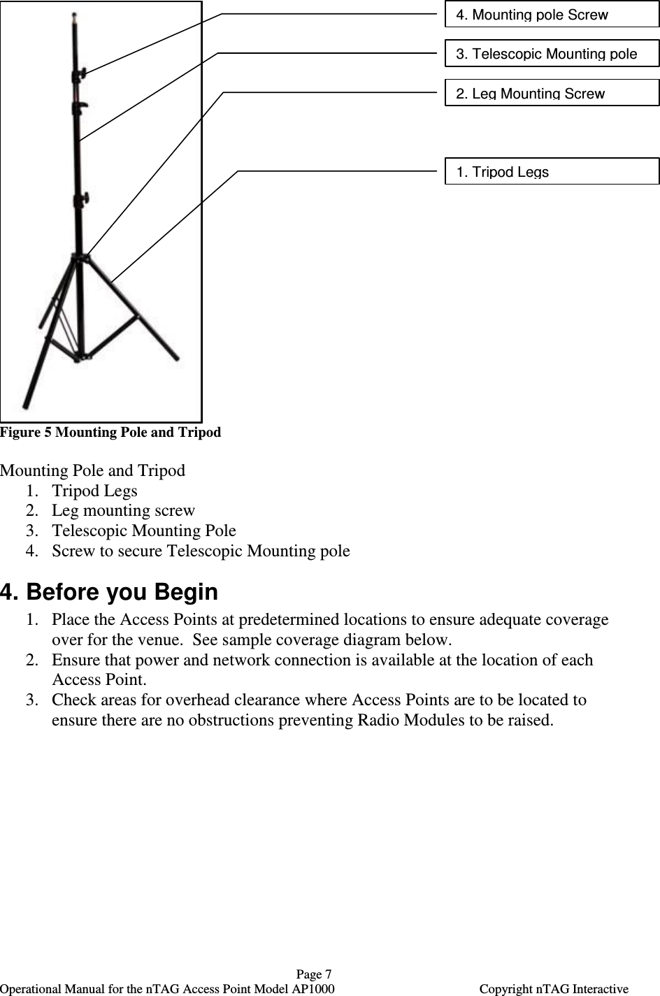
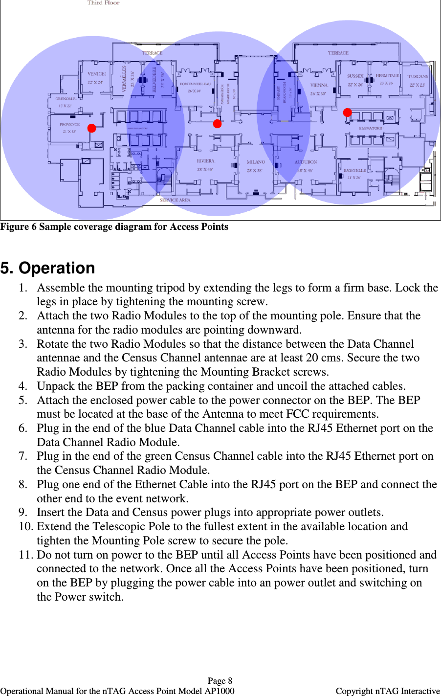
![Page 3 Operational Manual for the nTAG Access Point Model AP1000 Copyright nTAG Interactive 1. Notices This device complies with part 15 of the FCC rules. Operation is subject to the following two conditions: (1) This device may not cause harmful interference, and (2) this device must accept any interference received, including interference that may cause undesired operation. This Class [A] digital apparatus complies with Canadian ICES-003. Cet appareil numérique de la classe [A] est conforme à la norme NMB-003 du Canada. This device has been designed to operate only with a LinxTechnologys antenna, part number ANT-2.4-CW-RCT, with a maximum gain of 2.90 dBi. Other antennas having a gain greater than 2.90 dBi are strictly prohibited for use with this device. The required antenna impedance is 50 ohms. There are no end user serviceable parts inside the nTAG Access Point. Please return to nTAG Interactive for any servicing or repair. FCC Caution: To assure continued compliance, any changes or modifications not expressly approved by the party responsible for compliance could void authority to operate this equipment. 2. List of Components The nTAG Access Point Model AP1000 consists of the following components: • One Back End Processor (BEP) • Two Radio Modules o Data Channel Radio Module marked blue o Census Channel Radio Module marked green • One Mounting pole with tripod • One Power Cable for BEP • One Ethernet Cable to connect BEP to Event Server 3. Controls and connectors The following section shows the key controls and connectors for the components comprising the Access Point.](https://usermanual.wiki/nTAG-Interactive/400-00200/User-Guide-699324-Page-3.png)